

Page 1
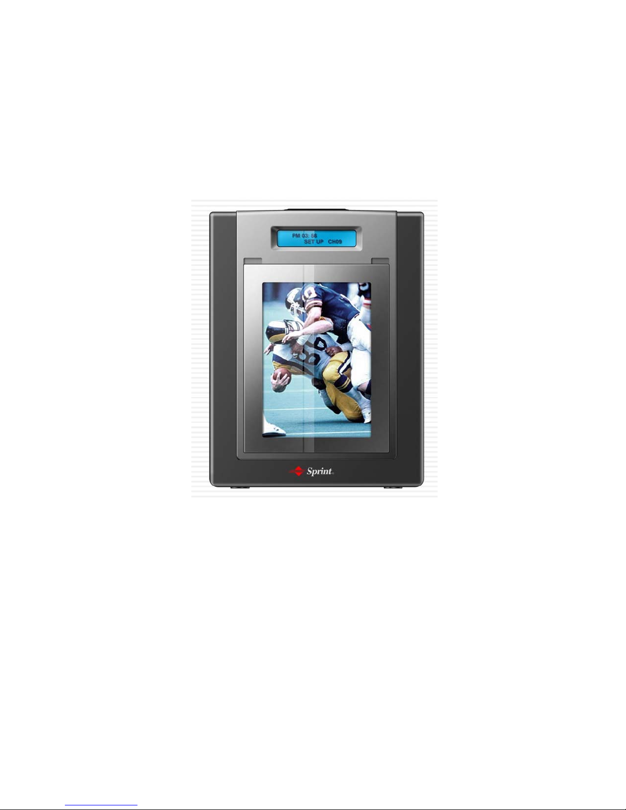
UUSS PPCCSS RReeppeeaatteerr SSyysstteemm
Manual
.
Wiirreelleessss DDaattee CCoommmmuunniiccaattiioonn CCoo..,, LLttdd..
W
22000055.. 0077.
Page 2

CONTENTS
11.. OOvveerrvviieeww..............................................................................................................................................................................3
11..11 PPuurrppoossee..................................................................................................................................................................................................3
11..22 AApppplliiccaabbllee RRaaggee......................................................................................................................................................................3
11..33 GGeenneerraall ..............................................................................................................................................................................................3
11..44 GGeenneerraall EEqquuiippeenntt FFeeaattuurreess......................................................................................................................................4
22.. TThhee SSttrruuccttuurree ff EEqquuiippmmeenntt ((FFuunnccttiioonnaall FFeeaattuurreess))................................................4
22..11.. TThhee SSttrruuccttuurree ooff SSyysstteemm..........................................................................................................................................6
22..22 FFoorrwwaarrddss............................................................................................................................................................................................7
22..33 BBaacckkwwaarrddss....................................................................................................................................................................................110
22..44 PPoowweerr SSuuppppllyy..........................................................................................................................................................................113
22..55 OOppeerraarriioonn aanndd OObbsseerrvvaattiioonn................................................................................................................................113
3
3
3
3
4
4
6
7
0
3
3
33.. SSyysstteemm SSttaannddaarrddss................................................................................................................................................114
33..11 EElleeccttrroonniicc FFeeaattuurreess........................................................................................................................................................114
44.. TThhee OOppeerraattiioonn ooff EEqquuiippmmeenntt............................................................................................................116
44..11 TThhee OOrrddeerr ooff EEqquuiippmmeenntt IInnssttaallllaattiioonn..................................................................................................117
44..22 TThhee OOppeerraattiioonn ooff EEqquuiippmmeenntt..........................................................................................................................117
55.. TTrroobblleesshhoooottiinngg........................................................................................................................................................118
55..11 WWhheenn nnoott ttuurrnn oonn tthhee ppoowweerr VVFFDD oorr lliigghhtt iinn tthhee FFoonntt............................................118
55..22 WWhheenn nnoott ccoommee oouutt tthhee ssiinnggaall oonn rreeppeeaatteerr..................................................................................118
4
4
6
7
7
8
8
8
18/2
Page 3
1. OVERVIEW
1.1 Purpose
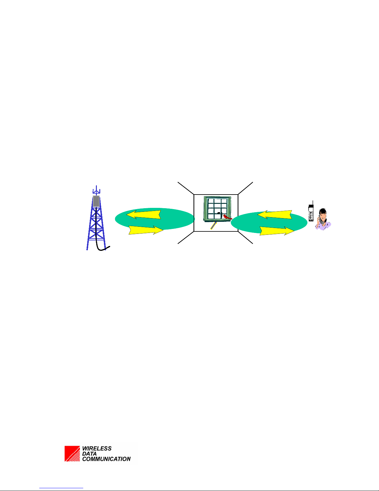
This repeater system is designed to provide high-quality service in communication
which inevitably come obstacles in the shadow area
1.2 Applicable Range
US-PCS-S1 repeater is providing the telecommunication services of the good quality
of the bad-lined & interrupted area in communication service area.
RepeaterRepeat
Repeater
er
1.3 General
To improve the equipment install-expenses and efficiency utility, Service signal
among ultra-mixed PCS signal of other operation preferentially amplify and relay to the
shadow area so that it would be provided good-quality service economically &
efficiently.
This repeater is using method by converting the weak RF signal from the Base
Station into IF band, amplifying and then resending the RF signal.
It is consist of Duplexer, SAW FILTER by IF, power supply device, controller and
exterior case, is designed of being satisfied with the spurious condition of high-output in
signal.
18/3
Page 4

1.4 General Equipment Features
z In-building (For home & office ) , Service in shadow area.
z Small & light Sized Equipment.
z Easy and simple installment
z Convenient Installment, Application and maintenance.
z Built-in Antenna
z Convenient Automatic Set-up Programmed
2. The Structure of Equipment (Functional Features)
The Repeater system is for the relaying system that can supply the services
Tx/Rx:1850~1910MHZ, Tx/Rx:1930~1990MHz by one equipment.
This is installing a wide service of 120MHz bandwidth in the shade area between the
18/4
Page 5
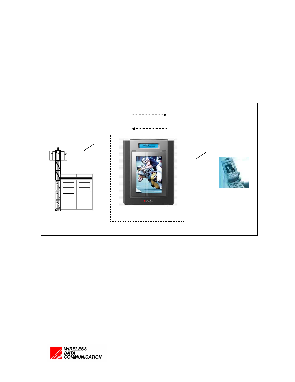
Base Station and Mobile Station. It improves the telecommunication quality by
amplifying the verified signal from coming out the Base Station and then selecting the
signal through the SAW Filter and adjusting to the same output.
Downlink:1.93GHz ~ 1.99GHz
Uplink :1.85GHz ~ 1.91GHz
Base Station
1.93GHz~ 1.99GHz
1.85GHz ~ 1.91Hz
Mobile Station
Repeater System
18/5
Page 6
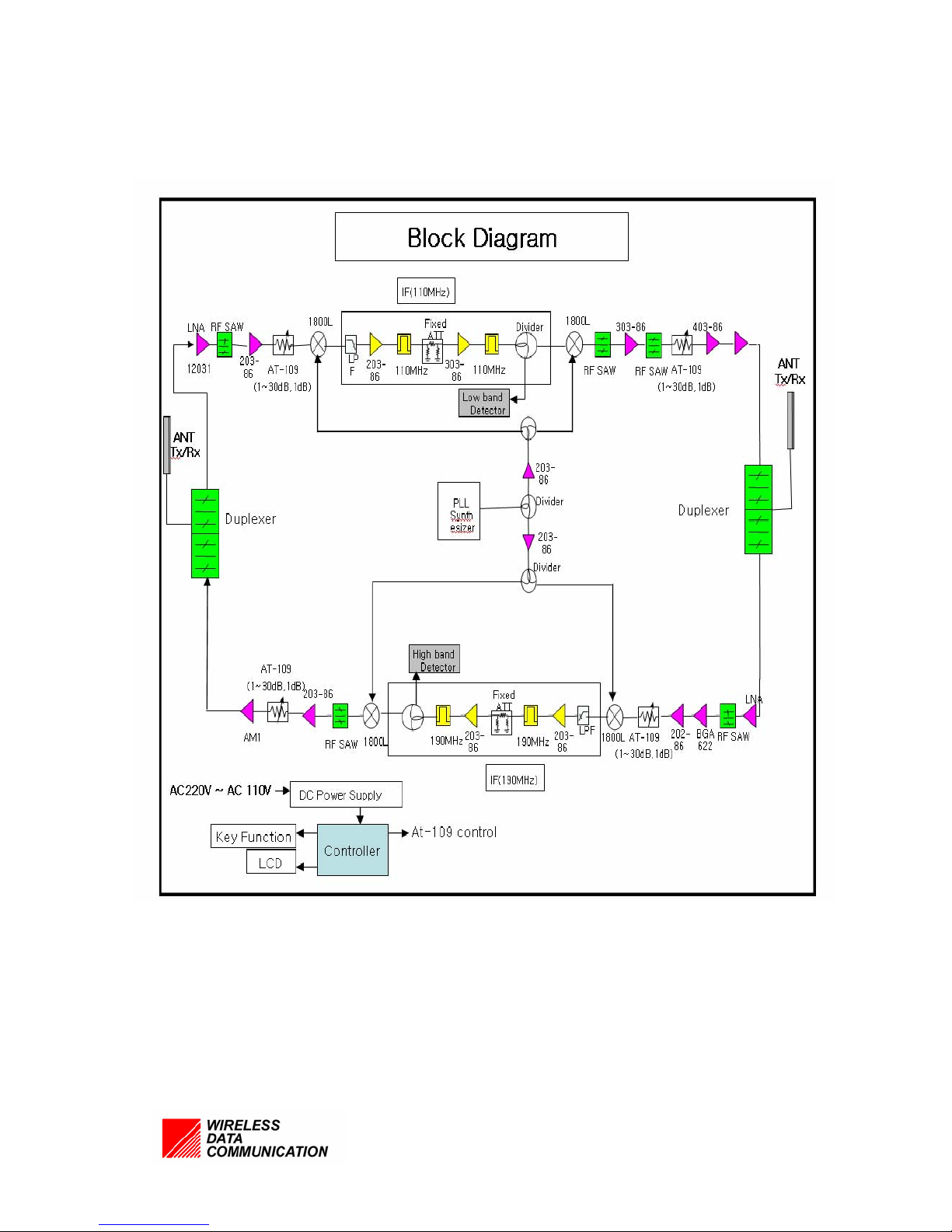
2.1 The Structure of System
<System Block Diagram >
18/6
Page 7
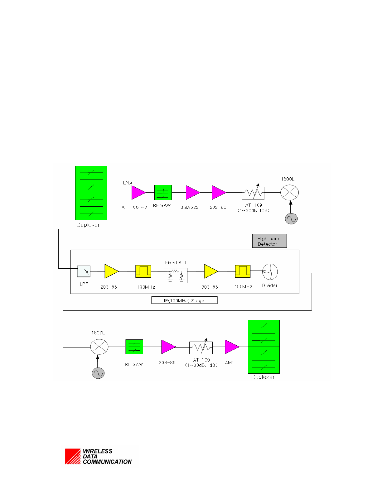
2.2 Downlink
This repeater consist of LNA receiving CDMA signal(Down Link) from the Base
Station and amplifying first step after filtering the other company’s signal through the
Duplexer, Down Converter converting the RF into IF signal, Amp amplifying the
power, and PLL Local for the Down/Up converting
The functions for each block are as follows:
<Downlink Block Diagram >
18/7
Page 8

2.2.1 DUPLEXER
Link Duplexer is a device to transfer Down Link signal and Up Link Signal by
using one port.
Down Link signal received Antenna from the BTS, it remove the other band signal
and transfer LNA signal.
Up Link signal is being filtered the last and come out forward Base Station.
The signal frequency relaying toward terminal from Base Station is 1850 MHz ~
1910Mhz.
The signal frequency relaying toward Base Station from the terminal is KTF:1930
MHz~1990 MHz.
Tx/Rx Isolation is more than 50 dBc.
2.2.2 LNA
LNA is as a AMP amplifying first step received the weak signals through the
DUPLEXER, has a excellent specific device of NF(1dB under)
It improves the whole system of NF and IP3 is rather high that can come out the
stable output.
2.2.3 DOWN CONVERTER
Down Converter would convert IF signal from low-noise amplified signal for
filtering SAW Filter having a good SCIRT.
In case of converting into IF signal it would be easier the process than RF signal,
it can receive excellent selectivity only passing through the setting frequency range.
18/8
Page 9

2.2.4 IF Block
IF block selects bandwidth, it can be chosen Convert IF signal by filtering SAW
Filter having a good SCIRT.
2.2.5 UP CONVERTER
UP Converter is excellent selectivity that the IF signal being filtered can supply
the RF signal as service signal.
2.2.6 AMP
AMP receives the converted signal from the UP converter and improves the
signal’s advantage adjustment and IP3 features together
2.2.7 PLL
PLL Local Oscillator is Synchronous signal which convert the signal to RF into IF,
IF into RF and has a good phase noise that can convert the frequency without
changed the signal features being input.
.
18/9
Page 10
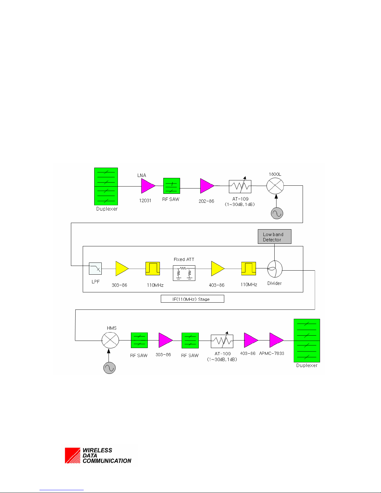
2.3 Up link
This repeater consist of LNA receiving CDMA signal(UP Link) from the Base
Station and amplifying first step after filtering the other company’s signal through
the Duplexer, Down Converter converting the RF into IF signal, HPA amplifying
the power, and PULL Local for the Down/Up converting.
The functions for each block are as follows:
<Up link Block Diagram >
18/10
Page 11

2.3.1 DUPLEXER
Link Duplexer is a device to transfer Down Link signal and Up Link Signal by
using one port
UP Link signal received Antenna from the terminal, it remove the other band
signal and transfer LNA signal.
Down Link signal is being filtered the last and come out in the way of Terminal.
The signal frequency relaying toward terminal from Base Station is 1930 MHz ~
1990MHz.
The signal frequency relaying toward Base Station from the terminal is
KTF:1850 MHz~1910 MHz.
Tx/Rx Isolation is more than 50 dBc.
2.3.2 LNA
LNA is as a AMP amplifying first step received the weak signals through the
DUPLEXER, has a excellent specific device of NF(1dB under)
It improves the whole system of NF and IP3 is rather high that can come out the
stable output.
2.3.3 DOWN CONVERTER
Down Converter would convert IF signal from low-noise amplified signal for
filtering SAW Filter having a good SCIRT.
In case of converting into IF signal it would be easier the process than RF signal,
it can receive a excellent selectivity only passing through the set frequency range.
2.3.4 IF Block
IF block selects bandwidth, it can be chosen Convert IF signal by filtering SAW
Filter having a good SCIRT.
18/11
Page 12

2.3.5 UP CONVERTER
UP Converter is a excellent selectivity that the IF signal being filtered can
supply the RF signal after converting into a service signal.
2.3.6 AMP
AMP receives the converted signal from the UP converter and improves the
signal’s advantage adjustment and IP3 features together.
2.3.7 PLL
PLL Local Oscillator is Synchronous signal which convert the signal to RF into
IF, IF into RF and has a good phase noise that can convert the frequency without
changed the signal features being input.
18/12
Page 13

2.4 Power Supply
z It would receive AC100V ~ 240V(50Hz~60Hz) and supply the power to the
equipment in DC7.5V(1.33A)
z Operation conditions is designed to work safely during -20 ~ 40
2.5 Operation & Observation
2.5.1 The function of VFD
It can be easily recognized configuration data through VFD in controlling of S/W1,
S/W2 which showing in the front.
SW1: Able to switch the Channel (1~12CH) to 5 MHz
• A1: No.1 CH (Down link :1850~1855MHz,UP link :1930~1935 MHz)
• A2: No.2 CH (Down link :1855~1860MHz,UP link :1935~1940 MHz)
• A3: No.3 CH (Down link :1860~1865MHz,UP link :1940~1945 MHz)
• D: No.4 CH (Down link :1865~1870MHz,UP link :1945~1950 MHz)
• B1: No. 5CH (Down link :1870~1875MHz,UP link :1950~1955 MHz)
• B2: No.6 CH (Down link :1875~1880MHz,UP link :1955~1960 MHz)
• B3: No. 7 CH (Down link :1880~1885MHz,UP link :1960~1965 MHz)
• E: No. 8 (Down link :1885~1890MHz,UP link :1965~1970 MHz)
• F: No. 9 (Down link :1890~1895MHz,UP link :1970~1975 MHz)
• C1: No. 10 CH (Down link :1895~1900MHz,UP link :1975~1980 MHz)
• C2: No. 11CH (Down link :1900~1905MHz,UP link :1980~1985 MHz)
• C3: No.12 H (Down link :1905~1910MHz,UP link :1985~1990 MHz)
SW2: RF ON/OFF function
18/13
Page 14
p
q
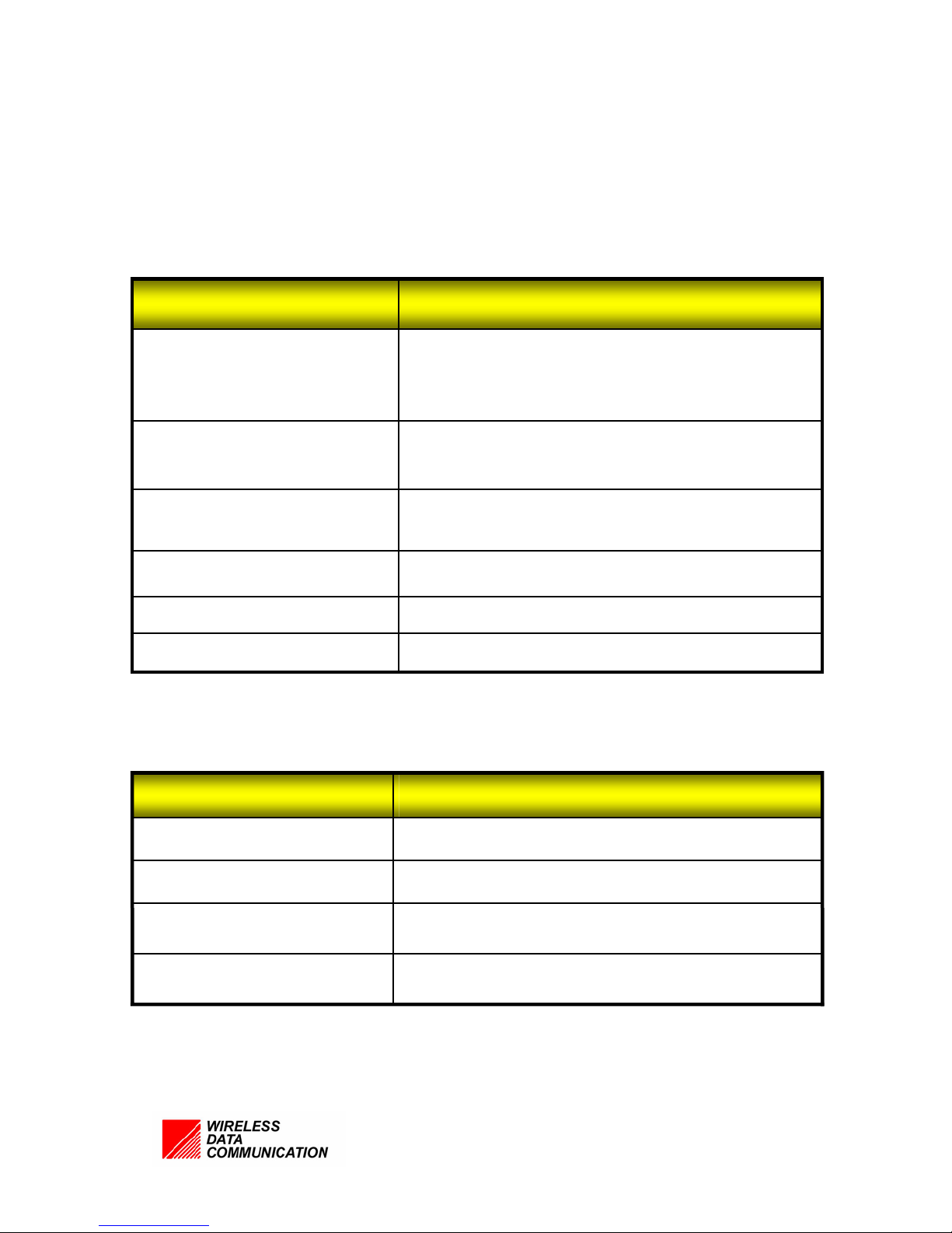
3. System standards
3.1 The Electronic characteristics
3.1.1 The RF characteristics
Specifications Items
Operating Frequency
Output power
RF Gain
Port to Port Group Delay
Noise Figure
edance
Im
3.1.2 Power Supply characteristics
1930MHz ~ 1990MHz Down link
1850MHz ~ 1910MHz Up link
8dBm Down link
18dBm Up link
60dB Up link
Less than or equal to 1 ms
Less than or e
ual to 5 dB
50Ω
Specifications Items
Power
Power Supply
Temperature range
Warranty period
DC 7.5V 2.4A
External Supply Input
-20°C ~ 40°C
1 year
18/14
Page 15
p
g
p
m
m
(
yp
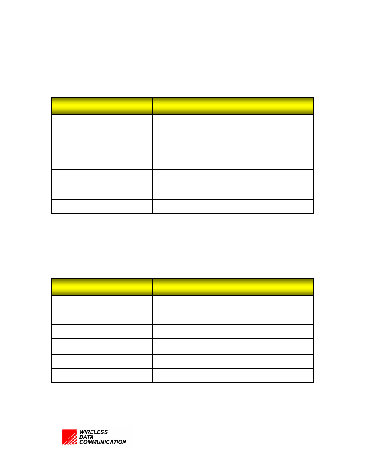
3.1.3 The Antenna characteristics
Specifications Items
Operating Frequency
Pattern
Antenna Gain
VSWR
Beamwidth
edance
Im
3.1.4 VFD characteristics
1930MHz ~ 1990MHz
1850MHz ~ 1910MHz
directional
8dBi
1 : 1.5
o
120
50Ω
Specifications Items
e
T
Sizw
W x H x T)
Viewing Area (W x H )
Weight
Volta
erating temp
O
e
Positive
80.0 x 36.0 x 10.5 m
64 x 16 m
45g
Max 5.5V
-20 ~ +70 °C
18/15
Page 16
(
y
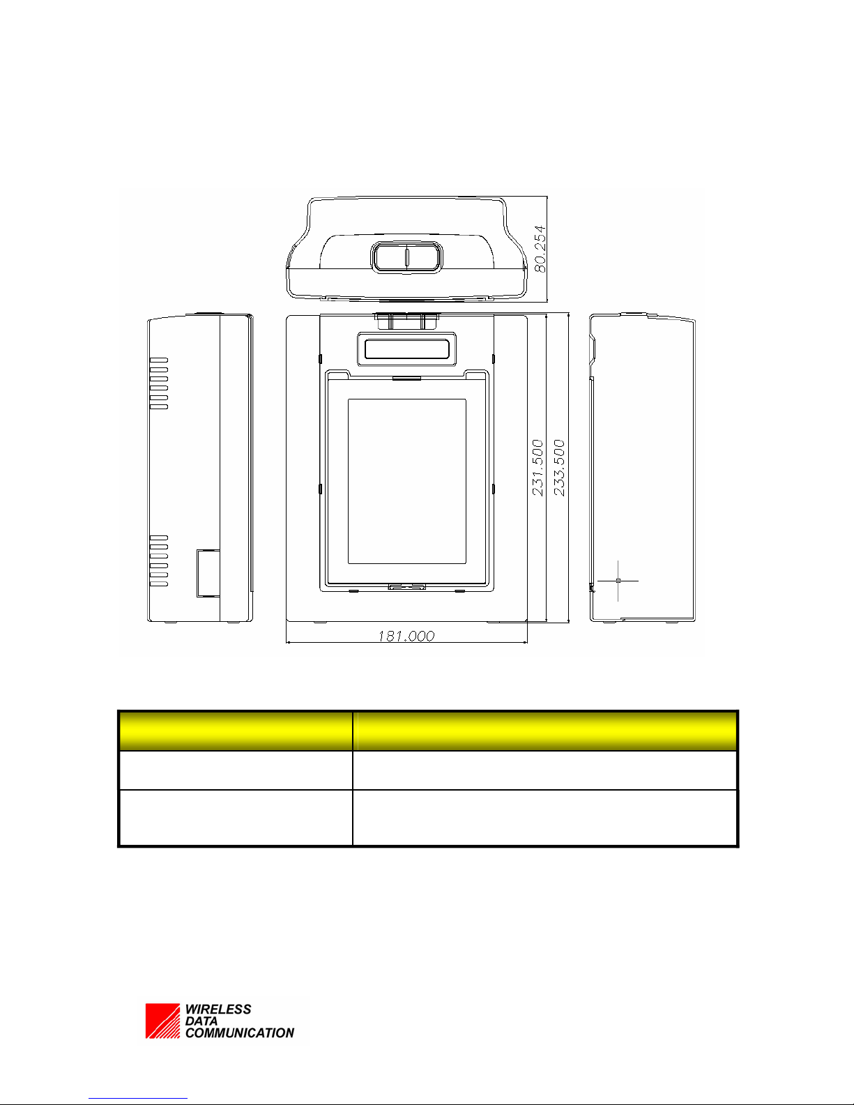
3.2 The Mechanical characteristics
Status Displa
Size
Specifications Items
181 x 233.5 x 80.254 (W x H x D) mm
7.126 x 9.193 x 3.14
18/16
STN Graphic LCD
W x H x D) inch
Page 17

4. The Operation of Equipment
4.1 The order of Equipment installation
Find the best widow receiving the best powerful signal of Handy-phone in checking
out every corner of home or office by using the handy-phone.
Take the suitable place and install the repeater safely in the window.
Connect the AC adapter in the repeater and plug in the power.
4.2 The equipment Operation
S1 system is as a exclusive CDMA repeater in the US PCS band, performing on
relaying the received signal from the Base Station and outputting to the mobile terminal
(forward), relaying the received signal from the mobile terminal and outputting to the
Base Station (Backward).
INFORMATION TO THE USER
“Note: The manufacturer is not responsible for any Radio or TV interference caused
by
unauthorized modifications to this equipment. Such modifications could void the
user’s
authority to operate the equipment.”
“CAUTION: RF Exposure to Radio Frequency Radiation.
This equipment must be installed and provided minimum separation distance of 20 cm
from the body of user and near by person. In addition to separation distance, this
device cannot be transmitted and operating in conjunction with any other transmitter
18/17
Page 18

or antenna.
5. Troubleshooting
5.1 Not turn on the power VFD or light in the Front.
Î Cuase
When does not connect the cable in the Power supply
When Back Light function does not work.
VFD abnormal
Î Correction
Check out the Power connection ( reset the power)
Check out if the Back Light has no problem.
Check out the VFD connection and if not problem, replace.
5.2 Does not come out the signal on repeater.
Î Cause
When the repeater not RF ON
When the channel (1~12CH) of repeater doesn’t’ meet the signal from the
BTS.
Î Correction
Turn on the repeater system on pressing the channel switch 2
Press the channel switch 1 and go though the work from 1~12
Check out the connection part of power in the PCS of repeater.
Check out being delivered any notice on the repeater for the abnormal work or
strange signal.
18/18
 Loading...