

Page 1
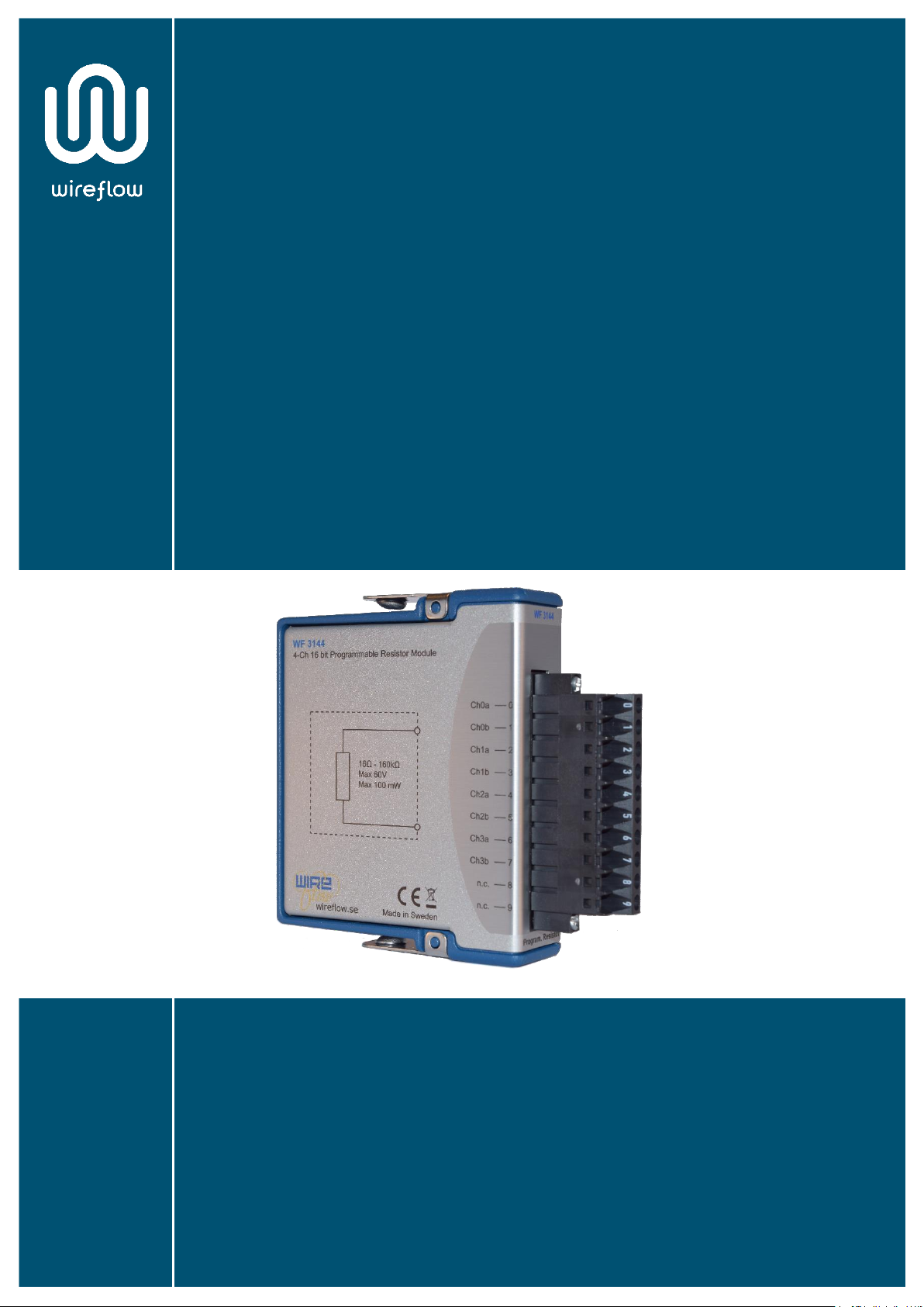
WF 3144
User Manual
AC0021-002, rev C
Page 2

WF 3144 | User Manual
1
© WireFlow 2018
AC0021-002, rev C
Contents
Support information ........................................................................................................... 2
Technical support and Product information ................................................................ 2
WireFlow headquarters .................................................................................................. 2
Important information ........................................................................................................ 2
Copyright ........................................................................................................................... 2
High risk activities ............................................................................................................ 2
Compliance ........................................................................................................................... 2
Device information .............................................................................................................. 3
Features ............................................................................................................................ 3
Specifications .................................................................................................................... 3
Calibration ........................................................................................................................ 4
Pinout ................................................................................................................................ 5
Software ................................................................................................................................ 6
Requirements ................................................................................................................... 6
Installation ........................................................................................................................ 6
Supported Platforms ....................................................................................................... 6
API ...................................................................................................................................... 7
Normal operation mode ............................................................................................. 7
Enhanced accuracy mode ........................................................................................... 8
Mixed mode .................................................................................................................. 8
Examples ........................................................................................................................... 9
Troubleshooting ................................................................................................................ 10
Enhanced mode output ................................................................................................ 10
Installation ...................................................................................................................... 10
Technical support and Professional services................................................................. 10
Waste Electrical and Electronic Equipment (WEEE) ....................................................... 11
Page 3

WF 3144 | User Manual
2
© WireFlow 2018
AC0021-002, rev C
Support information
Technical support and Product information
www.wireflow.se
WireFlow headquarters
WireFlow AB
Theres Svenssons gata 10
SE-417 55 Göteborg
Please see appendix “Technical support and Services” for more information.
© WireFlow AB, 2018
Important information
Copyright
The WF 3144 module and accompanying software driver is Copyright © 2011-2018,
WireFlow AB.
High risk activities
The software and hardware is not designed, manufactured or intended for use or
resale as on-line control equipment in hazardous environments requiring fail-safe
performance, such as in (but not limited to) the operation of nuclear facilities,
aircraft navigation or communication systems, air traffic control, direct life support
machines, or weapons systems, in which the failure of the Software could lead
directly to death, personal injury, or severe physical or environmental damage
("High Risk Activities"). WireFlow and its suppliers specifically disclaim any express
or implied warranty of fitness for High Risk Activities.
Compliance
CE - European Union EMC and Safety Compliance
This product meets the essential requirements of applicable European Directives,
as follows:
• Electromagnetic Compatibility (EMC) Directive 2004/108/EC
• RoHS Directive 2011/65/EU
Please contact WireFlow to get a copy of the Declaration of Conformity for the WF
3144 module
Page 4

WF 3144 | User Manual
3
© WireFlow 2018
AC0021-002, rev C
Device information
Features
• Four independent, galvanically isolated channels
• Entirely solid-state simulation
• High resolution with non-linear scaling
• Wide resistance range
• Enhanced accuracy mode
• On-board calibration memory
• LabVIEW driver included
• Compatible with NI VeriStand
• Combines permutations of real resistors to achieve desired value
Specifications
Number of Channels 4
Max Voltage 60V
Max Power 100mW/channel
Range 16Ω – 160kΩ
Max Error
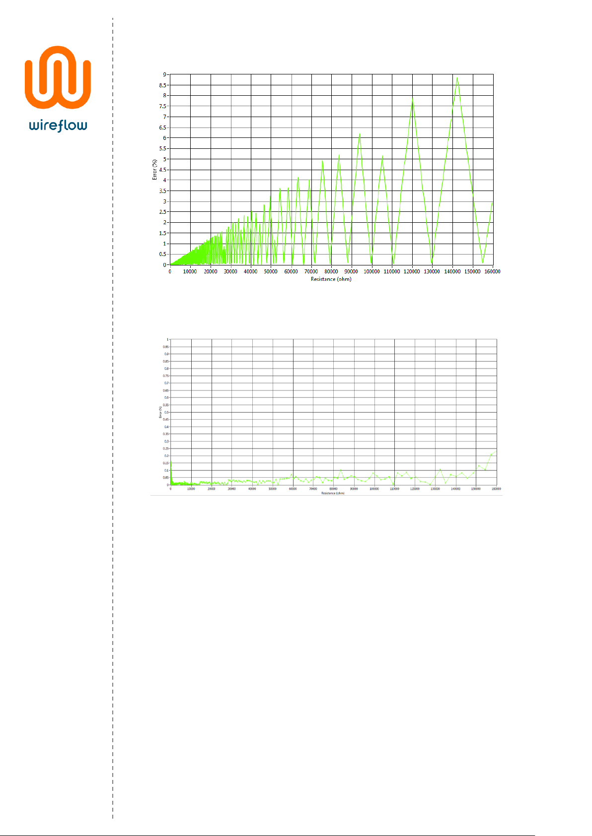
R < 100 Ω 0.03%
R < 1 k 0.1%
R < 10 kΩ 1%
R < 160 kΩ 10%
32 Ω < R < 160 kΩ 0,25% (Enhanced mode)
Update Rate 200S/s
Page 5
WF 3144 | User Manual
4
© WireFlow 2018
AC0021-002, rev C
Figure 1 – Error (%) versus Resistance in normal mode
Figure 2 – Error (%) versus Resistance in enhanced mode
Calibration
Each module is delivered calibrated. Modules that no longer stay within the Max
Error range given in the specifications section can be re-calibrated by WireFlow.
For questions regarding calibration, please contact WireFlow’s support, see chapter
“Technical Support and Professional Services”.
Page 6
WF 3144 | User Manual
5
© WireFlow 2018
AC0021-002, rev C
Pinout
16Ω -160kΩ
Max 60V
Max 100mW
a
b
Ch0 a
Ch0 b
Ch1 a
Ch1 b
Ch2 a
Ch2 b
Ch3 a
Ch3 b
n.c.
n.c.
0
1
2
3
4
5
6
7
8
9
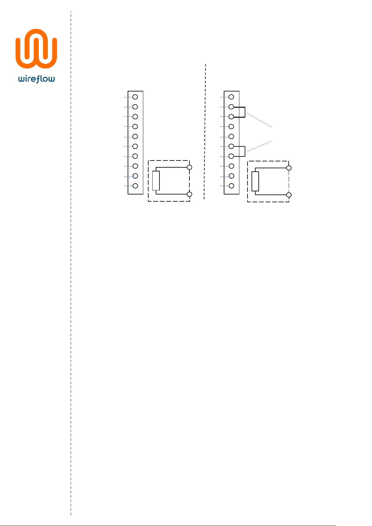
Normal mode Enhanced mode
32Ω -160kΩ
Max 60V
Max 100mW
a
b
Ch0 a
Ch0 b
Ch1 a
Ch1 b
Ch2 a
Ch2 b
Ch3 a
Ch3 b
n.c.
n.c.
0
1
2
3
4
5
6
7
8
9
External
jumper cables
Figure 3 – Pinout and connection diagram
Page 7

WF 3144 | User Manual
6
© WireFlow 2018
AC0021-002, rev C
Software
The WF 3144 is delivered with a LabVIEW driver to manage the module using FPGA
property nodes and IO nodes. This chapter describes the installation, requirements
and basic usage.
Requirements
• LabVIEW Full (version >= 2017 SP1
*
)
• LabVIEW FPGA module
• NI RIO (version >= 17.6)
• VI Package Manager (for installation)
Previous version of this driver (v2.0.4) is available on www.wireflow.se and supports LabVIEW2011
The WF 3144 driver currently requires the LabVIEW FPGA toolkit. The software for the WF
3144 is delivered as a VIPM packet (*.vip) and requires the free version of VI Package
Manager (VIPM) to be installed (available at jki.net or from ni.com).
Installation
The easiest way to install/update the WF 3144 software is (when VIPM is already
installed);
1. Double click the *.vip package
2. Follow the instructions in VIPM to select LabVIEW version where to install
the driver
3. Restart LabVIEW
Once installed the necessary files should be installed in the LabVIEW application
folders, see the API section for details.
Supported Platforms
The WF 3144 module can be used in any C Series chassis, with LabVIEW FPGA
programming enabled. This currently excludes the CompactDAQ series of chassis,
but includes cRIO, EtherCAT and FPGA expansion chassis.
Page 8
WF 3144 | User Manual
7
© WireFlow 2018
AC0021-002, rev C
API
Once the WF 3144 module has been added to the project the module can be
controlled using property nodes and IO nodes.
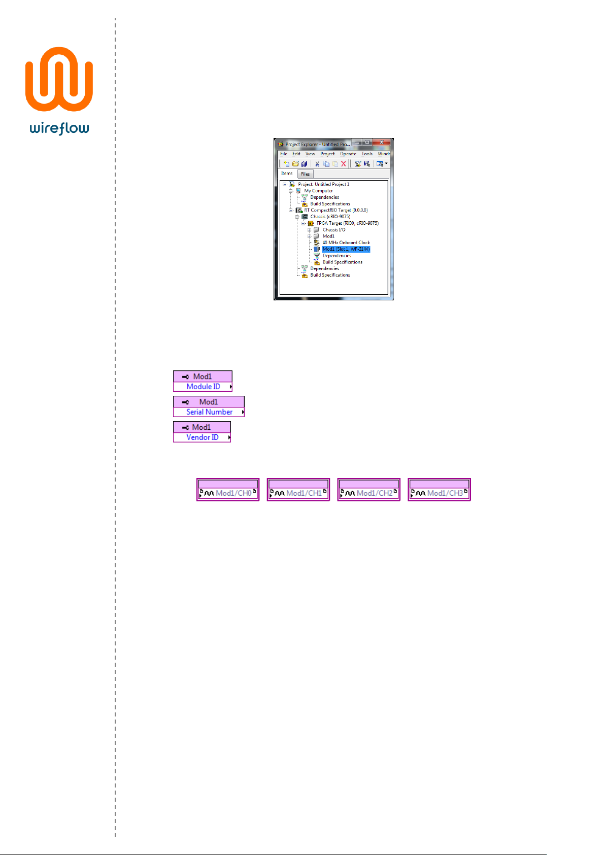
Figure 4 – The WF 3144 module added to the project
The property nodes return information about the current firmware, the
information returned is;
• This is the identification number of the WF-3144 module
• Serial number of the module
• Vendor identification number (in this case WireFlow)
The output resistance is set by the FPGA IO nodes.
Figure 5 – IO nodes for normal operation mode
To set infinite resistance (Open Circuit), use -1 (or any negative number) as the
resistance input.
Normal operation mode
In the normal operation mode each channel is managed separately (see IO nodes
in Figure 3), and the output resistance is available between the a- and b- terminals
of each channel. This mode has a non-linear accuracy scaling, with better accuracy
at lower resistance values.
Page 9
WF 3144 | User Manual
8
© WireFlow 2018
AC0021-002, rev C
Enhanced accuracy mode
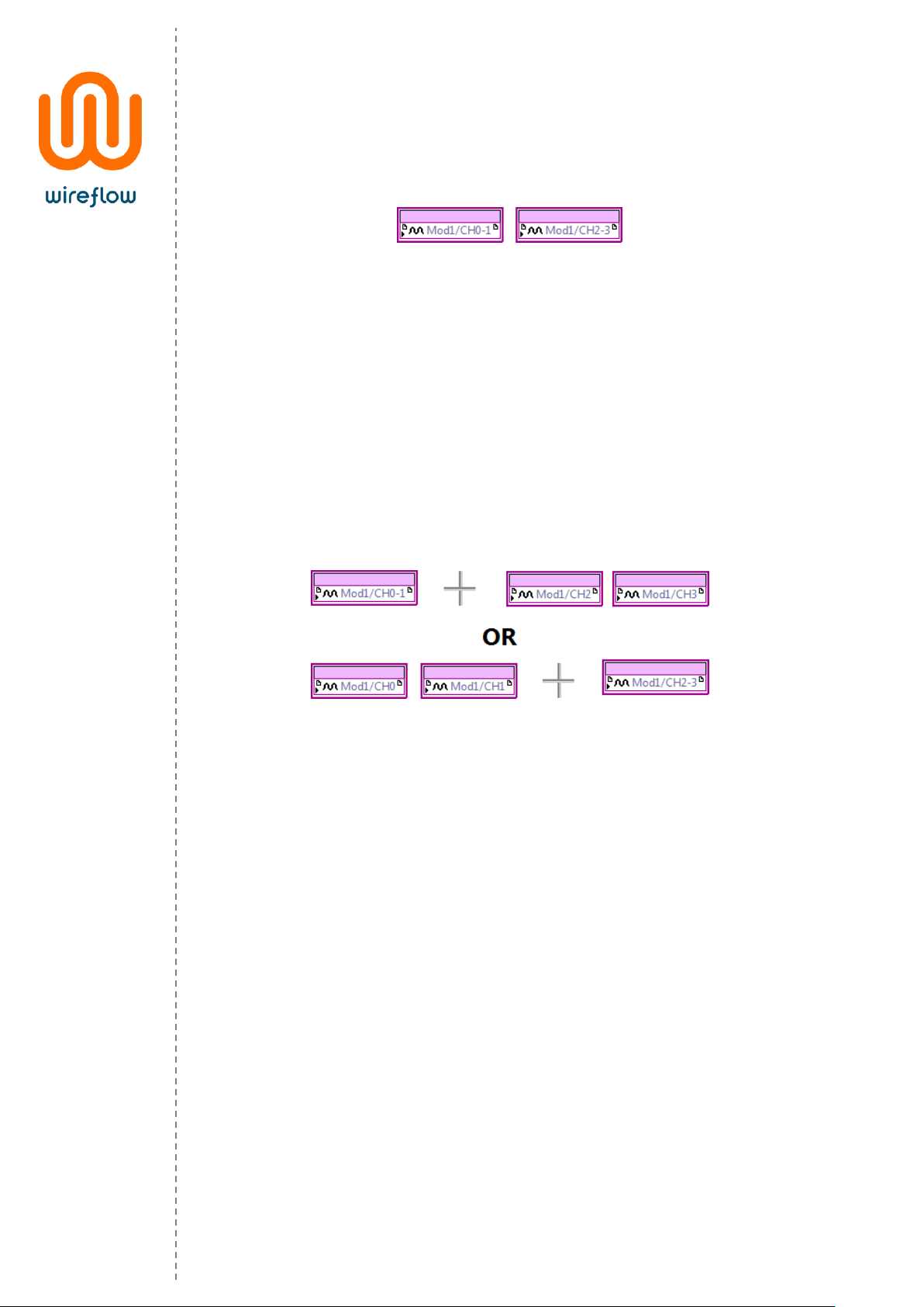
The enhanced accuracy mode uses two resistance channels in series (CH0-CH1 or
CH2-CH3).
Figure 6 – IO nodes for enhanced accuracy mode
In this mode the enhanced mode IO nodes should be used (see Figure 4). The IO
nodes for the separate channels should not be used.
Please note that the enhanced mode requires external cabling to get the
corresponding channels in series, i.e. a jumper cable between terminal b on the
first channel and terminal a on the second channel. The requested resistance is
then available between terminal a on the first channel and terminal b on the
second channel.
Mixed mode
The WF-3144 driver allows mixing of operation modes, e.g. CH0 and CH1 can be
used in normal mode while CH2 and CH3 are used in enhanced mode.
Figure 7 – Mixed mode operation
Page 10
WF 3144 | User Manual
9
© WireFlow 2018
AC0021-002, rev C
Examples
The shipping examples demonstrate the usage of the API driver methods. To find
the examples, open LabVIEW example finder and search for the WF 3144.
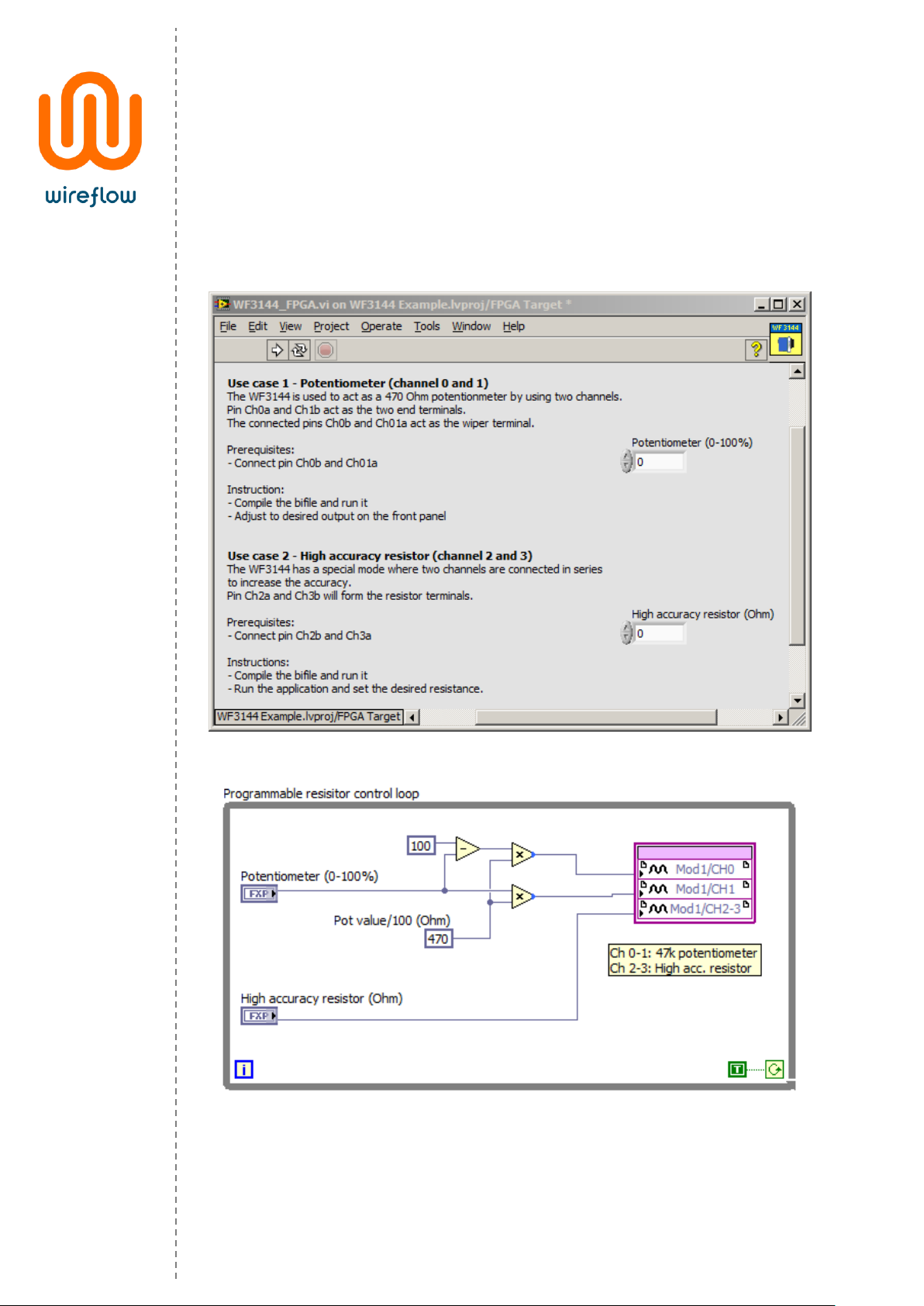
The example below shows how to simulate a potentiometer using two channels in
normal mode. It also shows how to the WF 3144 can act as a high accuracy resistor
by using two channels in enhanced accuracy mode.
Figure 8 – Front panel of WF 3144 example
Figure 9 – Block diagram of WF 3144 example
Page 11

WF 3144 | User Manual
10
© WireFlow 2018
AC0021-002, rev C
Troubleshooting
Enhanced mode output
Enhanced mode resistance requires an external jumper cable between the first
channel b-terminal and the second channel a-terminal. Failing to do this result in
an infinite resistance between CH0a and CH1b (or CH2a and CH3b).
Installation
During the installation progress the program folder is modified (new files are
added to the <LabVIEW> directory). On some operating systems or Windows
installations it might therefore be necessary to install the driver package with
administrator rights.
Technical support and Professional services
If you need to contact support please include the following information for faster
handling
• Product number
printed on the side of the module, ACxxxx
• Serial number
printed on the side of the module, s/n XXXXXX
• HW version
printed on the side of the module, vX.X.X
• Driver version (as indicated in VIPM)
• LabVIEW version
• NI-RIO version
• NI-FPGA version
• Target platform
• General description of the problem.
If possible, please include sample code that exemplifies the problem.
Please send support questions to [email protected], and set the subject to
“Support WF 3144”
Page 12

WF 3144 | User Manual
11
© WireFlow 2018
AC0021-002, rev C
Waste Electrical and Electronic Equipment
(WEEE)
EU Customers At the end of the product life cycle, all products must be sent
to a WEEE recycling center. For more information about how to, visit
www.wireflow.se/weee.
 Loading...