

Page 1

FCC ID: UXEMWSSTSR2 Report No. M060937_Cert_MWS_ST_SR
EMC Technologies Report Number: M060937_Cert_MWS_ST_SR
APPENDIX G
USER MANUAL
EMC Technologies Pty Ltd – 57 Assembly Drive, Tullamarine VIC 3043 Australia
www.emctech.com.au
Page 2
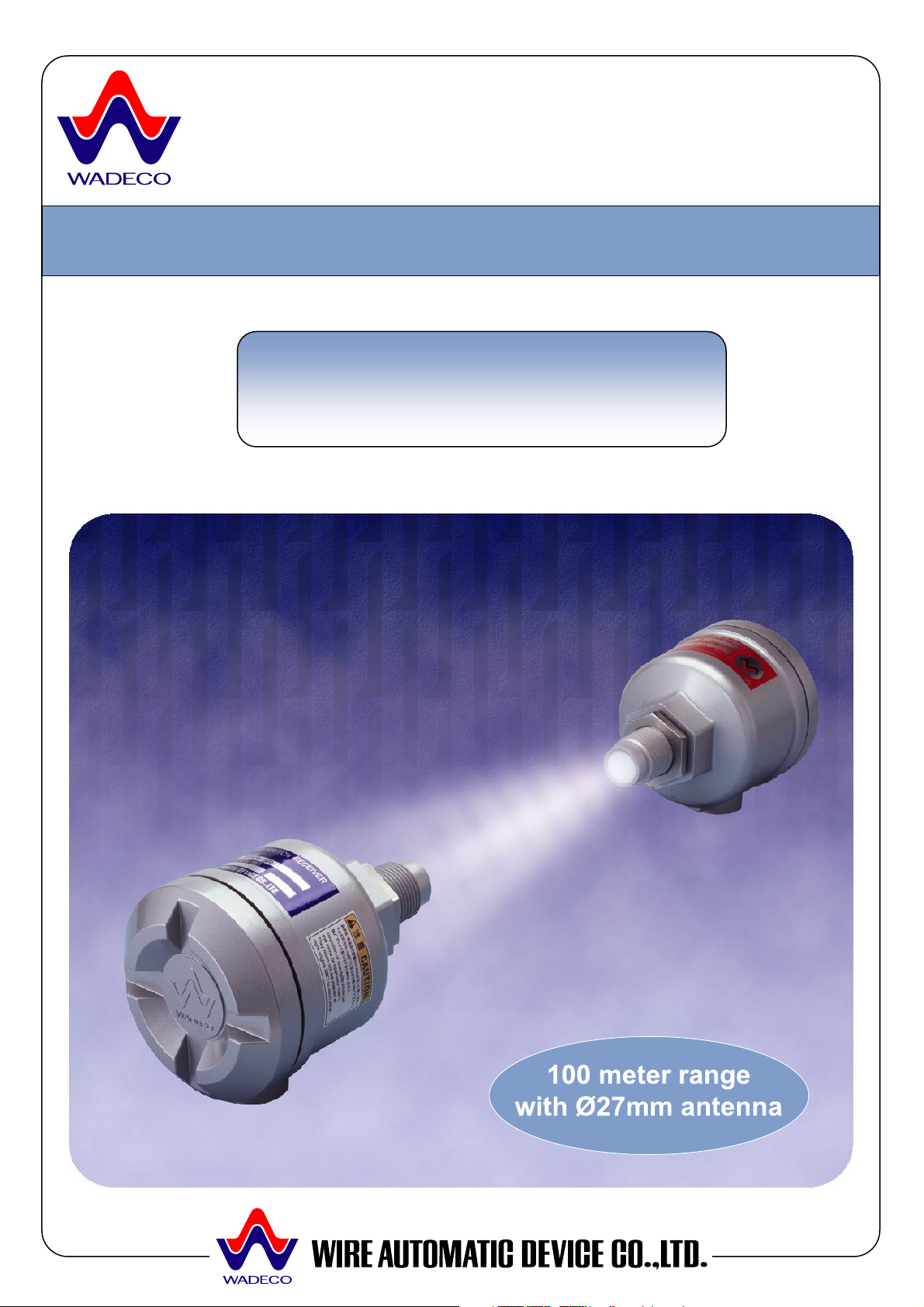
WADECO MICROWAVE LEVEL SWITCH MWS-ST/SR-2 DELUXE MODEL
MWS
MWSMWS
MWS
----
ST/SR
ST/SRST/SR
ST/SR
----
2 DELUXE
2 DELUXE 2 DELUXE
2 DELUXE
SERIES
SERIESSERIES
SERIES
MICROWAVE LEVEL SWITCH
OPERATION MANUAL
MWS-ST-2 [TRANSMITTER]
DELUXE MODEL
MWS-SR-2 [TRANSCEIVER]
1
Page 3

TABLE of CONTENTS
This equipment has been tested and found to
comply with the limits for a Class B digital
device, pursuant to Part 15 of the FCC Rules.
These limits are designed to provide reasonable
in a
This equipment
generates, uses and can radiate radio
frequency energy and, if not installed and used
in accordance with the instructions, may cause
ations.
However, there is no guarantee that
interference will not occur in a particular
installation. If this equipment does cause
harmful interference to radio or television
reception, which can be determined by turning
r is
to try to correct the interference by
Increase the separation between the
Connect the equipment into an outlet on a
t from that to which the
Consult the dealer or an experienced
OPERATION PRINCIPAL…... 3
FEATURES…………………… 4
SPECIFICATIONS…………... 5
APPLICATIONS………….….. 6
WADECO MICROWAVE LEVEL SWITCH MWS-ST/SR-2 DELUXE MODEL
FCC Modification Warning
Any changes or modifications not expressively
approved by WADECO LTD. could void the
user's authority to operate this equipment.
NOTE:
protection against harmful interference
residential installation.
harmful interference to radio communic
HARDWARE OPTIONS….…. 9
DIMENSIONS & PART
NUMBERS……………………. 11
INSTALLATION &
MOUNTING…………………… 13
WIRING……………………….. 16
FUNCTION OF SWITCHES,
INDICATORS AND
RHEOSTATS…………………. 18
the equipment off and on, the use
encouraged
one or more of the following measures:
• Reorient or relocate the receiving antenna,
•
equipment and receiver,
•
circuit differen
receiver is connected,
•
radio/TV technician for help.
SENSITIVITY
ADJUSTMENT……………….. 19
GUARANTEE………………… 20
2
Page 4
OPERATION PRINCIPAL
ST/SR type microwave sensor is
ansmitter
)
The transmitter emits a continuous, low
power microwave beam towards the
and an output relay is released
The sensor has wide application across all
. The
sensor is generally used for process control
ing presence/absence of product,
flow conditions and point level
sensor may
also be used as a proximity switch for
detection of vehicles such as dump trucks
Harsh environments may result in a buildup
of contaminants on the sensing head;
however, the sensor is easily able to
enetrate such buildup thanks to the high
When microwaves transmitted through air
encounter an object, some will be reflected,
through the object. The amount of
e object
Generally speaking, microwaves cannot
Microwaves can easily pass through
s output is regulated to assure
compliance with FCC Rule 15, covering field
With low output power, the sensor’s power is
ST/SR level switch is the first of
heterodyne detection
obsolete, diode
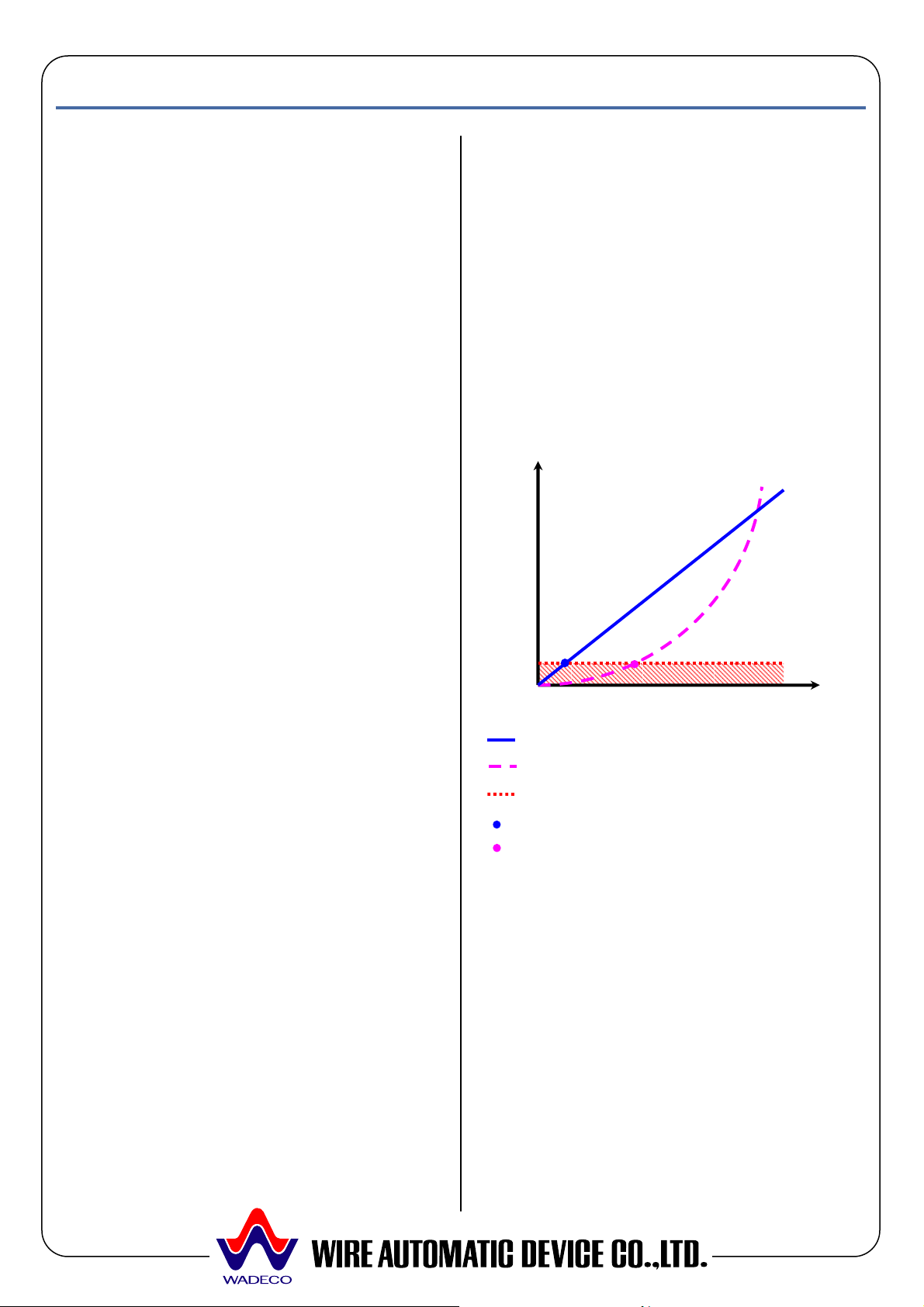
The heterodyne detection method gives
detection output that is proportional to the
received power level, whereas the diode
t
is proportional to the square of the received
Therefore the heterodyne method allows
detection with a minimum received power
that is lower than that of the minimum level
This
erating
range/penetrability without any increase in
the power of the transmitted microwave
General
The MWSa level switch consisting of a tr
(MWS-ST-2) and a transceiver (MWS-SR-2
installed face-to-face.
transceiver
when the beam is obstructed.
areas of industry where highly reliable, noncontact level detection is required
by monitor
flow/no
detection in bins and silos. The
WADECO MICROWAVE LEVEL SWITCH MWS-ST/SR-2 DELUXE MODEL
well below the American OSHA exposure
specifications as stated in Section 1910.97.
There are no health hazards to personnel
operating WADECO sensors: no license,
approval or caution sign posting is required.
Heterodyne vs. Diode Detection
The MWSits kind to utilize the
method rather than the, now
detection method.
Detection output
and rail cars.
Penetrability of Microwaves
p
penetrability of microwaves.
some absorbed and the rest will pass
microwaves passing through th
depends on its composition.
penetrate metals and are reflected; water
absorbs the most microwaves.
Received power level
Heterodyne method (WADECO)
Diode method (commonly used)
Noise level
Minimum received power: -70dBm
Minimum received power: -50dBm
detection method gives detection output tha
power level.
plastics, glass, ceramic, paper etc.
Safety of Microwaves
The sensor’
disturbance devices.
required by the diode detection method.
greatly increases the op
radiation.
3
Page 5
FEATURES
100m Range with heterodyne detection
27mm
antenna, thanks to the Heterodyne
process buildup on
antenna, firebrick, refractory etc., thanks to
is unaffected by surface
contaminants, flames, steam, vapor or
Easy initial beam alignment at installation,
Either broken beam (BLOCK) or unbroken
beam (UNBLOCK) detection method may
0.1~10secs.,
prevents instantaneous detection of falling
icator array displays the
point, allowing for visual sensitivity
e (CH1~4),
nterference. The sensor can also
operate in regular single channel mode by
The received power level may be output
The received power level and the
point are easily seen,
TRANS
CEIVER
CONTROLS
Beam obstructed
Approx. 100m range with a Ø
detection method.
High penetration
Easily penetrates
the increased operating range.
Unaffected by adverse environments
The sensor
airborne particles.
Simple beam alignment
thanks to the wide beam angle.
Selectable detection mode
be selected.
On delay time rheostat
On delay time, adjustable
WADECO MICROWAVE LEVEL SWITCH MWS-ST/SR-2 DELUXE MODEL
Transceiver
Transmitter
Beam unobstructed
Sensitivity-set-point
Relay OFF
material whist filling.
15 LED indicator bank
A 15 LED ind
received power level and the sensitivitysetadjustment and maintenance.
No set-to-set interference
Four channels are availabl
selectable by rotary switch, eliminating setto-set i
selecting CH0.
Analog output (optional)
as a 4 ~ 20mA analog signal.
Inspection window (optional)
sensitivity-setwithout removing the controller cover.
Received power levels
Relay ON
4
Page 6

SPECIFICATIONS
Type
NOTE: Phase of power supply must be the
Note: Operating distance may vary from
sensor to sensor and according to
ule 15 and
OSHA exposure specification stated in
Section 1910.97. Caution sign posting not
perate in single channel mode
by selecting CH0; doing so will disable the
(angle in half of receiving
On delay function
Output occurs on change of state, but only
after any delay period has past. Output
wave noise from noise simulator
: 1
ormal and
common modes), with the frequency of the
Note: Optional hardware is available for
WADECO MICROWAVE LEVEL SWITCH MWS-ST/SR-2 DELUXE MODEL
Transmitter : MWS-ST-2
Transceiver : MWS-SR-2
Power supply
AC100~120V ±10% 50/60Hz &
AC200~240V ±10% 50/60Hz
same for both transmitter and transceiver.
Operating distance
<80 meters
installation.
Frequency & transmission power
Approx. 24GHz, less than 10mW
Note: Complies with FFC Title R
required.
Number of channels
Single Channel Mode (CH0): 1
Multi Channel Mode (CH1~4): 4
Note: May o
multi channel function.
Received power level
Indicated by 1 of 15 LED indicators
Note: Indicator is fully illuminated
Sensitivity-set-point
Indicated by 1 of 15 LED indicators
Note: Indicator is half illuminated
Radiation angle
Approx. ±20°
value)
Output contact (on receiver)
1C relay contacts AC250V, 3A (COSØ=1)
Response time
25msec (when in multi channel mode)
10msec (when in single channel mode)
0.1 ~ 10sec
Condition of output function
relay is unexcited during output state.
Delay time from power on to function
Transmitter : Approx. 50msec.
Receiver : Approx. 5sec
Power consumption
Transmitter : 2VA
Receiver : 2VA
Noise tolerance
Square
(Rising time: 1 nanosecond, Width
microsecond), ±1.5KV (n
power supply in the 0º ~ 360º phase.
Operating ambient temperature
-10ºC ~ +55ºC
high temperature applications up to 600ºC.
Non-function ambient temperature
-20ºC ~ +70ºC
Continuous maximum pressure
0.5MPa
Note: Optional hardware is available for
high pressure applications.
Enclosure rating
IP65 Equivalent
Enclosure construction
Diecast aluminum
Color
Metallic silver grey
Weight
Transmitter : 1kg
Receiver : 1kg
5
Page 7
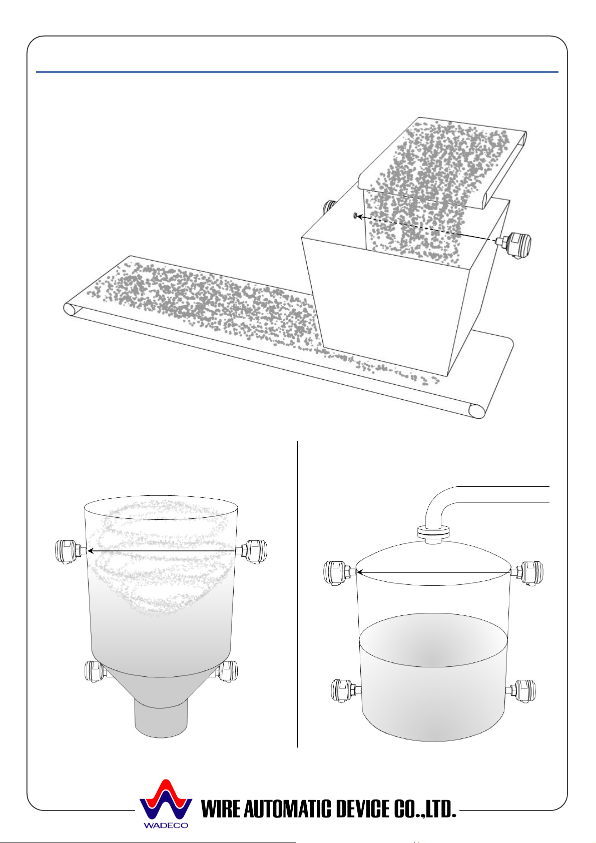
APPLICATIONS
Hi/low level of liquids in tanks,
Standard Applications
Blocked Chute Detection
Note: Install the sensors behind the
material flow to avoid false
detection.
Hi/low level of solids in cyclone
bins, hoppers, silos etc.
WADECO MICROWAVE LEVEL SWITCH MWS-ST/SR-2 DELUXE MODEL
Transceiver
MWS-SR- •
Transmitter
MWS-ST- •
and other storage vessels.
Transceiver
MWS-SR- •
Transceiver
MWS-SR- •
Transmitter
MWS-ST- •
Transmitter
MWS-ST- •
Transmitter
MWS-ST- •
Transceiver
MWS-SR- •
Transmitter
MWS-ST- •
Transceiver
MWS-SR- •
6
Page 8

WADECO MICROWAVE LEVEL SWITCH MWS-ST/SR-2 DELUXE MODEL
High Pressure Applications
NP Type
Polypropylene plug with flange mounting.
Note: See HARDWARE OPTIONS for more details.
Transmitter
MWS-ST- • -NP
Transceiver
MWS-SR- • -NP
Mounting detail
High pressure flange
Polypropylene
‘top hat’ plug
7
Page 9

WADECO MICROWAVE LEVEL SWITCH MWS-ST/SR-2 DELUXE MODEL
High Vibration & Hazardous Applications
Isolated, Non-invasive Mounting
Sensors may be protected from high temperatures, hazardous materials, vibration and shock
by providing detecting windows through which the microwaves can pass.
Detecting windows should be made of ceramic, glass, Teflon or polypropylene materials having
no water content, through which there is minimal loss of microwave energy.
The detecting windows should be al least 60mm in diameter as microwaves pass more easily
through larger apertures. The distance between the window and the antenna should be less
than 200mm.
The sensors should be fixed to an isolated support structure to protect against high vibration.
8
Page 10

WADECO MICROWAVE LEVEL SWITCH MWS-ST/SR-2 DELUXE MODEL
HARDWARE OPTIONS
Standard: Diecast Aluminum Antenna Head with Teflon Antenna cover
The standard enclosure is suitable for most applications that do not exceed the general
specifications (temperature, pressure, vibration etc).
Standard (as above) with Optional Flange Mounting
Threaded flanges are available in most standards (JIS, DIN, ANSI etc).
Rubber packing
SUS Lock nut
SUS Lock nut
SUS Flange
9
Page 11

WADECO MICROWAVE LEVEL SWITCH MWS-ST/SR-2 DELUXE MODEL
Optional NP Type: Polypropylene Head and Flange
The NP type is useful for applications where the process material is conductive and tends to
buildup, impairing the microwaves; the polypropylene plug should be placed into the standoff
portion preventing material from entering the standoff.
The NP type, when combined with a high pressure flange/seal, is also suitable for high pressure
applications. Threaded flanges are available in most standards (JIS, DIN, ANSI etc).
SUS Lock nut
Polypropylene head
SUS Flange
10
Page 12

WADECO MICROWAVE LEVEL SWITCH MWS-ST/SR-2 DELUXE MODEL
DIMENSIONS & PART NUMBERS
Note: Hardware dimensions are same for both the transmitter and transceiver.
Standard
Flange Mounting
NOTE: Other flange sizes are available upon request.
11
Page 13

NP Type
WADECO MICROWAVE LEVEL SWITCH MWS-ST/SR-2 DELUXE MODEL
Part Number Example: NP-56-075 = 5K65A Flange with 75mm long polypropylene head.
NOTE: Other flanges and polypropylene head lengths are available upon request.
12
Page 14

INSTALLATION & MOUNTING
The transmitter emits liner polarized
microwaves; as such it is necessary to align
the transmitter and its corresponding
ceiver in the same plane. The cable
ceiver
n the same direction, or be
If the units are installed with the cable
entries at 90º to each other they will not
The sensors should be mounted with the
me
Note that the sensors do not have to be
perfectly aligned, thanks to the wide beam
angle, however suitable care should be
taken.
Set-to-set interference
ceiver sets are
installed in close proximity to each other,
one set should be mounted at 90º to the
2 comes with 4 channels, selectable
set
interference. As such, installation of multiple
so as
to minimize material buildup on the antenna.
This is especially important if the process
material contains moisture. Microwaves are
able to penetrate most surface
containments; however it is recommended
that you optimize the installation to gain
Microwaves are able to penetrate walls
conductive materials such
as refractory/firebrick, ceramic, plastic, glass
etc. Microwaves can not penetrate metallic
or conductive wall linings: a hole must be
made and a suitable process connection
The ambient temperature between the
should not vary
General Guidelines
Mounting angle
trans
entry of both the transmitter and trans
should be facing i
180º opposite each other.
Transmitter
Transmitter
function.
Transmitter
Elevation angle
antennas facing each other on the sa
horizontal axis.
Transceiver
Transceiver
Transceiver
WADECO MICROWAVE LEVEL SWITCH MWS-ST/SR-2 DELUXE MODEL
If two transmitter trans
other to eliminate set-to-set interference.
Transmitter 1
Transmitter 2
Transceiver 1
Transceiver 2
Note that the Deluxe Level Switch MWSST/SRby rotary switch, to eliminate set-to-
sets as shown above may not be necessary.
Mounting flush
It is desirable to mount the units flush
maximum reliability.
Penetrability of walls
made from non-
welded to the vessel.
Temperature Variation
transmitter and transceiver
by more that 10ºC.
13
Page 15

WADECO MICROWAVE LEVEL SWITCH MWS-ST/SR-2 DELUXE MODEL
Mounting
Standard Mounting
Transmitter or transceiver
The sensor is threaded into an internal half connector welded to the wall. The sensor should be
mounted flush with the inside of the vessel and the SUS lock nut used to fix the sensor in position.
Apply liquid sealant into screw hole and/or any gaps.
Optional Flange Type Mounting
SUS lock nut
SUS Flange User’s flange
Flanges are optionally available in most standard sizes. The sensor’s flange is bolted to the
process connection flange supplied by the user.
Installation on sloped walls may be accomplished with a pipe and Teflon window as shown above.
Note: The length and diameter of the pipe are critical to ensure optimal performance; consult
your representative or the factory before deciding on these dimensions, we will advise you
on the most appropriate dimensions for your application.
G1 (1”) threaded coupling
SUS lock nut
Teflon window
Pipe
14
Page 16

WADECO MICROWAVE LEVEL SWITCH MWS-ST/SR-2 DELUXE MODEL
Optional NP Type Mounting
SUS lock nut
Polypropylene head
SUS Flange User’s flange
The polypropylene head is placed in the stand-off portion of the pipe and mounted flush with the
inside of the vessel.
The polypropylene head is not fixed to the sensor; rather it is sandwiched between the two flanges.
Use suitable gaskets for high pressure applications.
15
Page 17

WIRING
!
!
!
!
!
Do not disconnect the wires connected to ground, either inside or
outside the sensor. If they are disconnected it may cause electrocution
or damage the circuits.
Do not touch live terminals of the sensor as high voltages may be
present.
Do not disassemble any part of the sensor’s electronics.
Turn off the power before connecting to any terminals. If this is not
done electrocution or damaged circuits may result.
To prevent electrocution, ensure that the ground terminal of the sensor
is connected to ground before turning on the power.
If there are problems with grounded wires, or if other protective
functions are absent, do not turn on the power.
Before turning on the power, confirm that the rated voltage of the
controller is compatible with the voltage of the power supply.
Ensure that the ground wire is connected to earth before connecting
any other wires to the controller.
WADECO MICROWAVE LEVEL SWITCH MWS-ST/SR-2 DELUXE MODEL
Warning
!
16
Page 18

WADECO MICROWAVE LEVEL SWITCH MWS-ST/SR-2 DELUXE MODEL
Terminal Connection for AC Power Supply Type MWS-ST/SR-2
**AC 100V~120V ±10%, 50/60Hz
**AC 200V~240V ±10%, 50/60Hz
Note:
• The MWS-ST/SR-2 is not available with DC24V power supply.
• The phase of the power supply must be the same for both transmitter and transceiver.
Selection of Detection Mode and Relay Configuration
Transmitter Transceiver
Detection Mode Beam broken BLOCK
Beam unbroken
UNBLOCK
Terminal Number 4 & 5 5 & 6 4 & 5 5 & 6
Unpowered state Closed Open Closed Open
Powered
state
Non-detecting
state
Detecting state Closed Open Closed Open
Open Closed Open Closed
17
Page 19

WADECO MICROWAVE LEVEL SWITCH MWS-ST/SR-2 DELUXE MODEL
FUNCTION OF SWITCHES, INDICATORS AND RHEOSTATS
Transmitter MWS-ST-2
Part name Description
Power indicator
①
②
Channel selector
Block button
③
④
Terminals
⑤
Ground
Transceiver MWS-SR-2
Part name Description
①
Mode selection switch
Sensitivity rheostat
②
Delay time rheostat 0.1 ~ 10sec. delay period after state changes
③
④
Channel selector
⑤
Received power level indicators
Output indicator ON (red): Illuminates on output
⑥
Output indicator OFF (green): Illuminates on no output
⑦
Terminals Power supply (terminals 1 ~ 3) and relay contacts (4~6)
⑧
Ground Connected to chassis
⑨
Green when power is on
Multi channel mode: CH 1 ~ 4
Single channel mode: CH 0
Blocks transmission
Power supply (1~3)
Connected to chassis
BLOCK: Outputs on broken beam
UNBLOCK: Outputs on unbroken beam
For sensitivity adjustment
Multi channel mode: CH 1 ~ 4, Single channel mode: CH
0
Received power level: indicated by one of 15 LEDs
Sensitivity-set-point: indicated by one of 15 LEDs
18
Page 20

WADECO MICROWAVE LEVEL SWITCH MWS-ST/SR-2 DELUXE MODEL
Before adjusting the sensitivity:
to 0 (single channel
f you are installing more
3 or 4
The phase of the power supply to must be the same for both the transmitter(s) and the
Set the mode selection switch to BLOCK. Turn sensitivity rheostat fully counter clockwise
The received power level
Turn the
ay between the
from above, a suitable delay time must be
late the beam
SENSITIVITY ADJUSTMENT
• Ensure that there is a clear line of sight between the transmitter and transceiver,
• Set the CHANNEL selector on both the transmitter and transceiver
mode) if you are installing one transmitter/transceiver set only: i
than one transmitter/transceiver set, in close proximity, then select channel 1, 2,
(multi channel mode) to prevent set-to-set interference.
•
transceiver(s).
Transmitter MWS-ST-2
• Apply power to the unit. The green POWER indicator will illuminate.
Transceiver MWS-SR-2
• Apply power to the unit. Either the red ON or the green OFF indicator will illuminate.
•
(minimum).
• Turn the delay time rheostat fully counter clockwise (minimum).
• The red output indicator ON will illuminate.
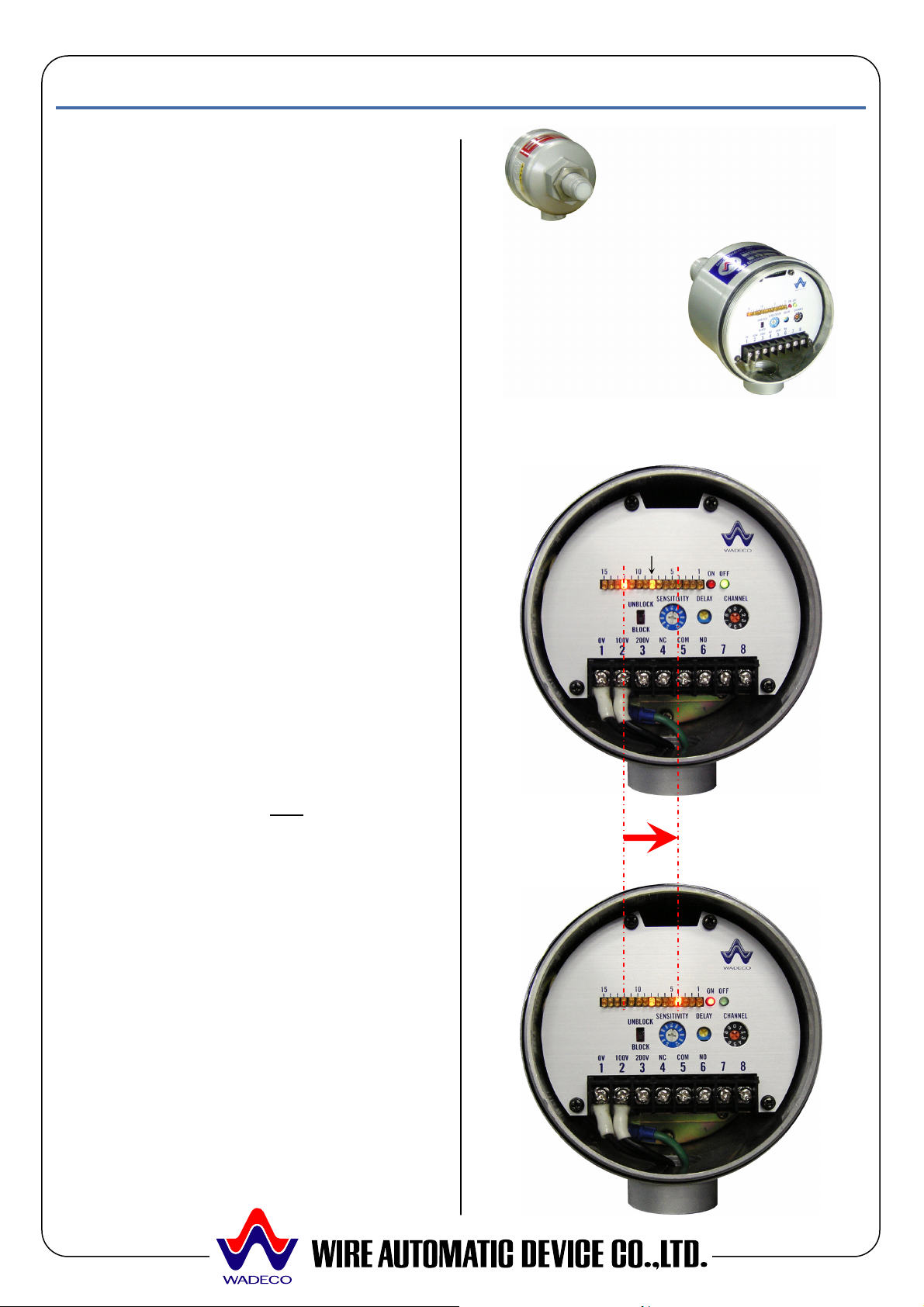
• The sensitivity is adjusted visually using the 15LED indicator array.
and sensitivity-set-point are indicated on the receiver by a bank of 15 LEDs.
sensitivity rheostat clockwise until the sensitivity-set-point is located halfw
received power level in the BEAM UNOBSTRUCTED and the BEAM OBSTRUCTED states.
BEAM UNOBSTRUCTED BEAM OBSTRUCTED
Received power level Received power level
Sensitivity-set-point
• For an application where material is introduced
provided to avoid instantaneous detection of falling material.
• To use UNBLOCK output mode, switch the mode selection switch to UNBLOCK.
• When adjusting the delay time, use the TEST button on the transmitter to simu
being blocked.
19
Page 21

WADECO MICROWAVE LEVEL SWITCH MWS-ST/SR-2 DELUXE MODEL
GUARANTEE
Guarantee Period
The guarantee period is for 1 year from the date of delivery.
Conditions
Any sensor that malfunctions during the guarantee period, as a result of a manufacturing fault, will
be repaired free of charge once it has been returned to the factory.
The cost of freight will be borne by the buyer. This guarantee does not cover any malfunction
resulting from conditions listed below:
1) When used under conditions or in environments not stated in the manufacturer's
specifications or brochures.
2) When the cause of the malfunction is not the result of the operation of the unit itself.
3) When repairs or adjustments have been performed by anyone other than the manufacturer.
4) When used for purposes other than for what it was intended.
5) When the cause of the malfunction was not predictable at the time of delivery or within the
scientific know-how of that time.
6) When the cause of the malfunction is due to a natural disaster.
The guarantee is not transferable to any second party.
Service
On site service and/or experimentation by WADECO personnel/technicians is not included in the
unit's price. If requested WADECO will provide an estimate of the cost for such services.
Wire Automatic Device Co., Ltd. (WADECO Ltd.)
1-9-27 Jokoji, Amagasaki-shi, Hyogo-ken 660-0811, JAPAN.
Tel: +81-6-6482-3838, Fax: +81-6-6481-6321
Email: sales@wadeco.co.jp
Web: http://www.wadeco.co.jp
20
 Loading...