

Page 1
INSTRUCTION MANUAL
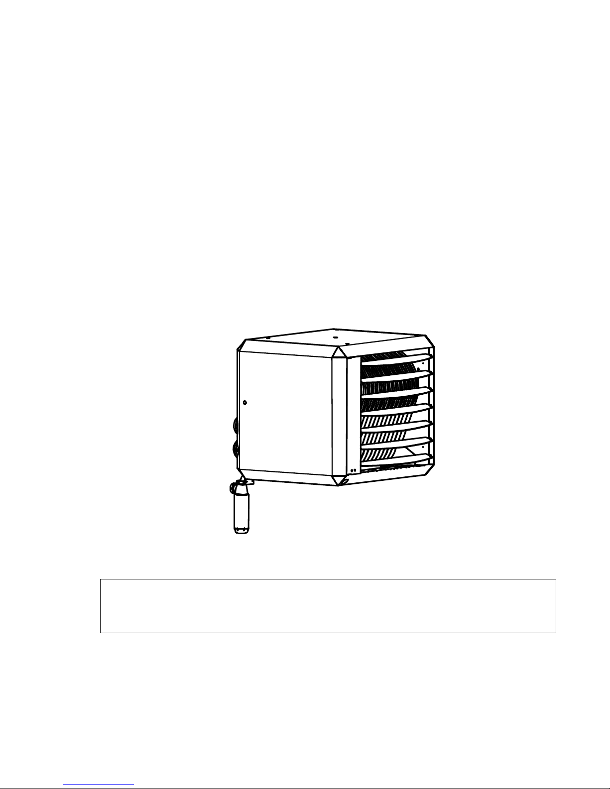
PREMIX UNIT AIR HEATER
TYPE HR
Production from 2014
THIS DOCUMENT MUST ABSOLUTELY BE READ BEFORE STARTING THE
INSTALLATION.
INSTRUCT USER AND LEAVE THIS DOCUMENT WITH HEATER FOR
REFERENCE.
Instruction manual version GB 109g
Heaters for GB
date: 01-02-2018
heaters for natural gas G20 and Propane
Page 2

Instructions condensing Air heaters type HR
Page 2/31
1 Introduction:
This installation and user manual is produced specifically for the gas, electrical and mechanical
installer , it also gives instructions how to use and maintain the heater.
2 Content:
Page
1 INTRODUCTION: 2
2 CONTENT: 2
3 GENERAL 3
3.1 G
UARANTEE
3
4 APPLICATION RESTRICTIONS 3
4.1 PRE-
CHECK
3
4.2 P
ROTECTION DEGREE
4
5 TECHNICAL DETAILS: 4
6 INSTALLATION 7
6.1 P
OSITIONING
7
6.2 G
AS CONNECTION
9
6.3 E
LECTRICAL CONNECTION
9
6.4 A
IR INTAKE / COMBUSTION PRODUCTS DISCHARGE
11
6.5 C
ONDENSATE DISCHARGE
13
7 FUNCTIONING OF THE UNIT 14
7.1 G
ENERAL
14
7.2 H
EAT DEMAND
14
7.3 D
ELTA
-T-
REGULATION (TEMPERATURE CONTROLLED DE-STRATIFICATION FAN
) 14
7.4 S
UMMER VENTILATION
14
7.5 H
IGH LIMIT PROTECTION
14
7.6 F
LUE TRANSPORT SUPERVISION
15
7.7 D
ESCRIPTION HEATER CONTROL
HC 15
8 PUTTING INTO OPERATION AND ADJUSTMENT 16
8.1 G
ENERAL
16
8.2 S
TART BY USING THE SERVICE-BUTTON
17
8.3 S
TART BY USING THE THERMOSTAT
17
8.4 T
O SIMULATE A LOCK OUT CONDITION
17
9 ADJUSTING THE GAS-CONTROL 18
10 PROBLEM SOLVING 18
10.1 G
ENERAL
18
11 MAINTENANCE / SPARE PARTS 21
11.1 G
ENERAL INSPECTION
21
11.2 I
NSPECTION OF THE HEATER
21
11.3 I
GNITION ELECTRODE
21
12 EXAMPLES ELECTRICAL INSTALLATION 22
12.1 T
HERMOSTAT CABLE
22
12.2 I
NSTALLATION WITH MODULATING ROOM THERMOSTAT
22
12.3 I
NSTALLATION OF MORE HEATERS ON ONE THERMOSTAT
22
Page 3
Instructions condensing Air heaters type HR
Page 3/31
13 ELECTRICAL DIAGRAM 25
14 EXPLODED VIEWS AND SPARE PARTS 27
14.1 S
PARE PARTS
27
14.2 E
XPLODED VIEW
HR10-20 28
14.3 E
XPLODED VIEW
HR30-60 29
14.4 E
XPLODED VIEW
HR80-120 30
15 CE CERTIFICATE & DECLARATION 31
3 General
The premix unit air heater is provided with sophisticated control sequence to maintain a
comfortable room temperature and even air distribution.
It is paramount that that the installation and maintenance of this appliance are carried out by
qualified gas engineers, and strictly according to our instructions.
This is a condensing heater. This means a condensate water discharge system should be
installed according to local regulations. Never block this discharge.
3.1 Guarantee
The guarantee is invalidated when the air heaters are not installed in accordance with this
manual.
4 Application restrictions
Important!
The installation en maintenance of this air heater should be performed by an
authorized competent installer in accordance with this manual.
This appliance is not intended for use by persons (including children) with reduced physical,
sensory or mental capabilities, or lack of experience and knowledge, unless they have been
given supervision or instruction concerning use of the appliance by a person responsible for
their safety. Children may not play with this heater.
4.1 Pre-check
Before unpacking and installation, please check (i.e. on the data badge) if the heater is in
accordance with the order and if it is suitable for the local present provisions (gas type, gas
pressure, electrical supply etc.)
The Installation must comply with all applicable local and national standards.
The installation of the air heater must be in accordance with the relevant requirements of the
Gas Safety regulations (for example in GB; The Institute of Gas Engineers IGE UP-1 and 2),
building regulations and the IIE regulations also incorporating the gas safety (installation and
use) regulations. Other national and/or local regulations may apply (the Local Authority ,Fire
Officer and Insurers)
The competent installer must make sure the heater operates correctly and must instruct the
user about the safe operation of the heater.
A ventilation gap of 30 cm is required from the top and bottom of the heater to any flammable
materials.
If this heater is drawing its combustion air from within the room in where it is located, the
necessary combustion ventilation requirements must be followed for gas safety regulations.
The heater should not be installed in areas containing any corrosive or explosive vapours , in
high moisture or dust concentrations, at negative pressures or temperatures higher than 30°C ;
please consult Winterwarm or your supplier. The guarantee is then invalidated..
Page 4
Instructions condensing Air heaters type HR
Page 4/31
Make sure that the warm air can be blown out freely. There should absolutely be (no possibility
of) materials within 5m from the front of the heater.
The heater has been tested in detail on safety and correct operating settings before leaving the
factory. It has been adjusted for the type of gas that is stated on the data badge. Should there
be any doubt , please contact the manufacturer.
4.2 Protection degree
The heater has a protection degree of IP20, this means for use in a dry and not very dusty
environment. This is also the case for the Winterwarm room-thermostat.
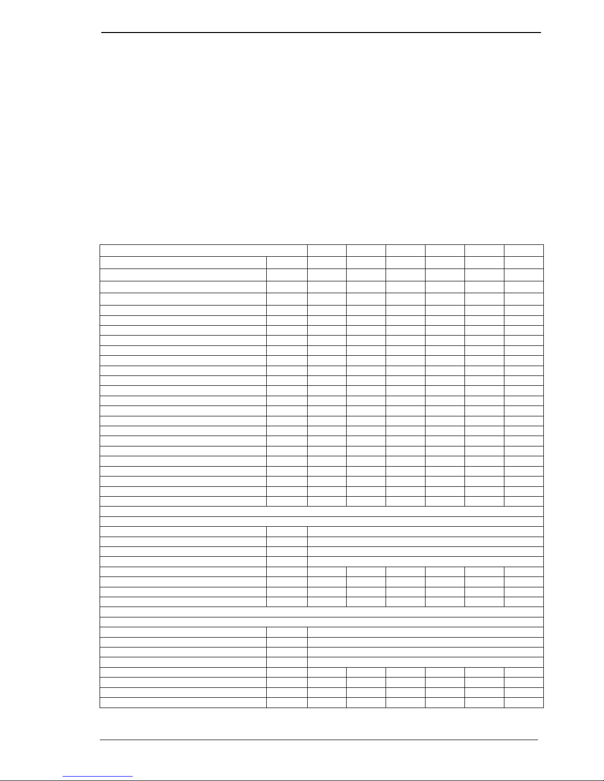
5 Technical details:
Type HR
10 20 30 40 50 60
Maximum nominal heat input (H.I.) kW 12,5 20,0 30,0 40,0 50,0 60,0
Minimum nominal heat input (H.I.) kW 4,0 6,0 9,0 12,0 15,0 18,0
Efficiency max. power % 96,0 96,0 96,5 97,0 96,5 96,6
Efficiency 30% power % 106,0 106,0 106,0 106,5 106,0 106,0
Maximum heat output kW 12,0 19,2 29,0 38,8 48,3 58,0
Minimum heat output kW 4,2 6,4 9,5 12,8 15,9 19,1
Max air output (warm) m3/hr 2.000 2.600 3.000 4.500 5.000 6.000
Throw horizontal (max) m 15 20 23 26 28 30
Gas connection G” ½” bin ½” bin ¾” bui ¾” bui ¾” bui ¾” bui
Electrical Voltage [50 Hz] V 230 230 230 230 230 230
Electrical power max. kW 0,250 0,250 0,250 0,450 0,450 0,600
Electrical power min.
kW 0,250 0,250 0,250 0,450 0,450 0,600
Electrical power standby
kW 0,004 0,004 0,004 0,004 0,004 0,004
Electrical current A 1,1 1,1 1,2 2,0 2,6 2,6
Emission efficiency, (ηs,flow) % 97,6 96,4 94,6 95,0 94,8 94,6
Seas. space heating efficiency % 90,4 90,1 88,7 89,9 89,2 89,4
NOx emission (GCV) mg/kWh 30 21 33 40 31 44
NOX class 5 5 5 5 5 5
Flue amount max. kg/hr 19,4 31,1 48,3 64,2 80,2 96,2
Thermostat bus system (low voltage) Ja Ja Ja Ja Ja Ja
Sound level (average @ 4 meter) dBA 45 45 45 47 48 49
Suspension height horizontal throw min. m 1,7 1,7 1,7 1,7 1,7 1,7
Flue length max. m 9 9 9 9 9 9
Weight m 45 50 75 85 105 110
Natural gas G20, heater version 3.3
Nominal supply pressure G20 mbar. 20
Supply pressure (min-max) G20 mbar. 17-25
Gas category Cat. I2H
Class Class. B23, C13, C33
Max gas consumption G20 m3/hr 1,3 2,1 3,2 4,2 5,3 6,3
CO2 High G20 % 9,5 9,5 9,2 9,2 9,2 9,2
CO2 Low G20 % 9,0 9,0 8,8 8,8 8,8 8,8
CO (@ 0%O2) mg/kWh 4 5 1 1 3 3
Propane, G31, heater version 3.4
Nominal supply pressure G31 mbar. 30-50
Supply pressure (min-max) G31 mbar. 25-50
Gas category Cat. I3P
Class Class. B23, C13, C33
Max gas consumption G31 kg/hr 1,0 1,6 2,4 3,2 4,0 4,8
CO2 High G31 % 10,7 10,7 11,0 11,0 11,0 11,0
CO2 Low G31 % 10,3 10,3 10,5 10,5 10,5 10,5
CO (@ 0%O2) mg/kWh 13 8 3 1 1 1
Page 5
Instructions condensing Air heaters type HR
Page 5/31
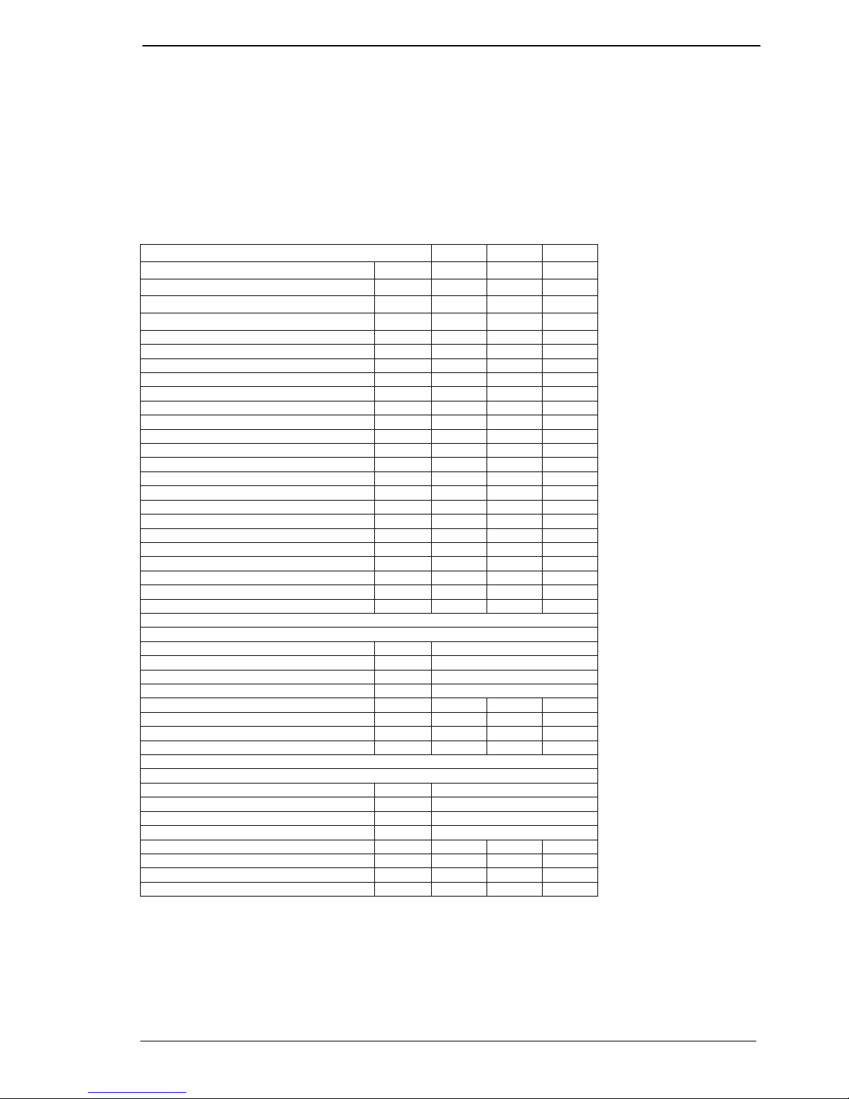
HR80, 100, 120
The HR80 & 100 & 120 heaters are respectively 2 x HR40, 50 & 60 heaters been placed on top
of each other in cascade in one casing with 1 gas connection, 1 combined air inlet, 1 combined
flue outlet, 1 electrical connection, 1 thermostat connection and 1 condensate drain. For the
proper functioning and to prevent interaction between the two burners, a gravity check valve
has been placed between the premix burner fan and the burner.
Please note that when more then only this heater is connected to one thermostat the micro
switches on the print boards in the heaters have to be set different.
See section 12.3 multiple heaters on 1 room thermostat.
Type HR
80 100 120
Maximum nominal heat input (H.I.) kW 80,0 100,0 120,0
Minimum nominal heat input (H.I.) kW 24,0 30,0 36,0
Efficiency max. power % 97,0 96,8 96,5
Efficiency 30% power % 105,0 105,0 105,0
Maximum heat output kW 77,6 96,8 115,8
Minimum heat output kW 25,2 31,5 37,8
Max air output (warm) m3/hr 8.500 10.000 12.000
Throw horizontal (max) m 30 30 33
Gas connection G” 1” int. 1” int. 1” int.
Electrical Voltage [50 Hz] V 230 230 230
Electrical power max. kW 0,900 1,000 1,050
Electrical power min.
kW 0,900 1,000 1,050
Electrical power standby
kW 0,010 0,010 0,010
Electrical current A 3,9 4,4 4,7
Emission efficiency, (ηs,flow) % 95,5 95,6 95,5
Seas. space heating efficiency % 88,8 89,0 89,1
NOx emission (GCV) mg/kWh 38 33 36
NOX class 5 5 5
Flue amount max. kg/hr 128,4 160,4 192,4
Thermostat bus system (low voltage) Ja Ja Ja
Sound level (average @ 4 meter) dBA 50 51 52
Suspension height horizontal throw min. m 1,7 1,7 1,7
Flue length max. m 9 9 9
Weight m 180 195 205
Natural gas G20, heater version 3.3
Nominal supply pressure G20 mbar. 20
Supply pressure (min-max) G20 mbar. 17-25
Gas category Cat. I2H
Class Class. B23, C13, C33
Max gas consumption G20 m3/hr 8,4 10,6 12,6
CO2 High G20 % 9,2 9,2 9,2
CO2 Low G20 % 8,8 8,8 8,8
CO (@ 0%O2) mg/kWh 1 3 3
Propane, G31, heater version 3.4
Nominal supply pressure G31 mbar. 30-50
Supply pressure (min-max) G31 mbar. 25-50
Gas category Cat. I3P
Class Class. B23, C13, C33
Max gas consumption G31 kg/hr 6,4 8,0 9,6
CO2 High G31 % 11,0 11,0 11,0
CO2 Low G31 % 10,5 10,5 10,5
CO (@ 0%O2) mg/kWh 1 1 1
Page 6
Instructions condensing Air heaters type HR
Page 6/31
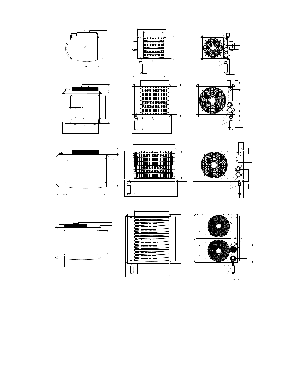
490 125
285
245
M10
420
495
420
680
M10
M10
100 110 85
65
65
85
35
O
40
IN O80
OUT O80
Gas 1/2"
Type 10 & 20
575
795
670
565
575
650 125
470
545
M10
4x M10
M10
115140 110
100
105
Gas 3/4" ext.
INO80
OUTO80
325
400
180
=
=
35
85
180 815
470
650 125
4X M10
565
670
1065
Gas 3/4" ext.
100
115
105
11014035
85
IN O80
OUT O80
O
40
O
40
Type 30 & 40
Type 50 & 60
280
280
280
840
815227
600
812 75
280
1115
1090
1195
840
87
462
11045
158
158
Gas 1" int.
Ø40
Type 80, 100 & 120
225
IN Ø130
OUT Ø130
Page 7
Instructions condensing Air heaters type HR
Page 7/31
6 Installation
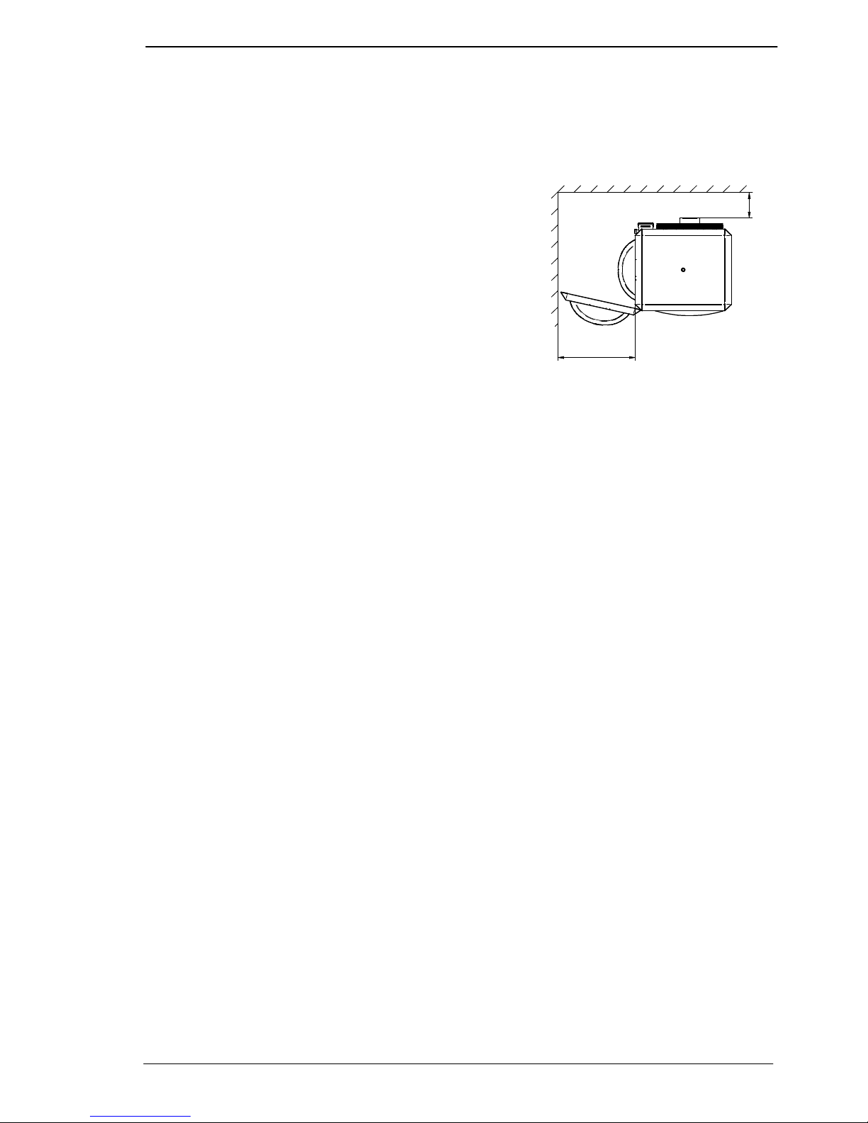
6.1 Positioning
• Check that the support is solid enough.
• The heater is designed as free hanging. The heater
should be able to blow the warm air free from any
ducting or obstacles. Also the air intake should be
free.
• Keep sufficient distance between the heater and any
obstruction , in connection with safety and access for
service and maintenance. Pay particular attention to
any flammable materials. Please take into account
the possibility to open the door of the heater for the
necessary service and maintenance work . Make
sure the air flow to and from the heater is unhindered. Any obstacles should be a minimum
of 5 metres away from the front of the heater.
• The heater can be installed horizontally or on an angle of maximum 45 degrees downwards.
• The heaters type 10 and 20 are provided with 2 off M10 threaded sockets as fixing points
(see the dimension diagram).
• The types 30 and 40 have in the middle a M10 socket and also 4 sockets on the top corners
of the heater
• The types 50 and 60 have on the top and bottom 4 M10 sockets. (see drawings)
• Use preferably the Winterwarm suspension kits.
• Make sure that after fitting, there is no mechanical tension on any connecting gas or electric
supplies.
• If the heater is installed with the air stream vertical downwards the maximum suspension
height is 8 meters. Otherwise the warm air will not reach the floor.
Attention:
See the application-restrictions in this manual (Chapter 4) for further installation restrictions.
min 250
10 t/m 30 min. 500 mm
40 t/m 60 min 660 mm
Page 8
Instructions condensing Air heaters type HR
Page 8/31
B
1
5
0
3
9
0
A
C
XR10-30 XR40-60
HR10-20 HR30-40
A 550 665
B 640 815
C 800 990
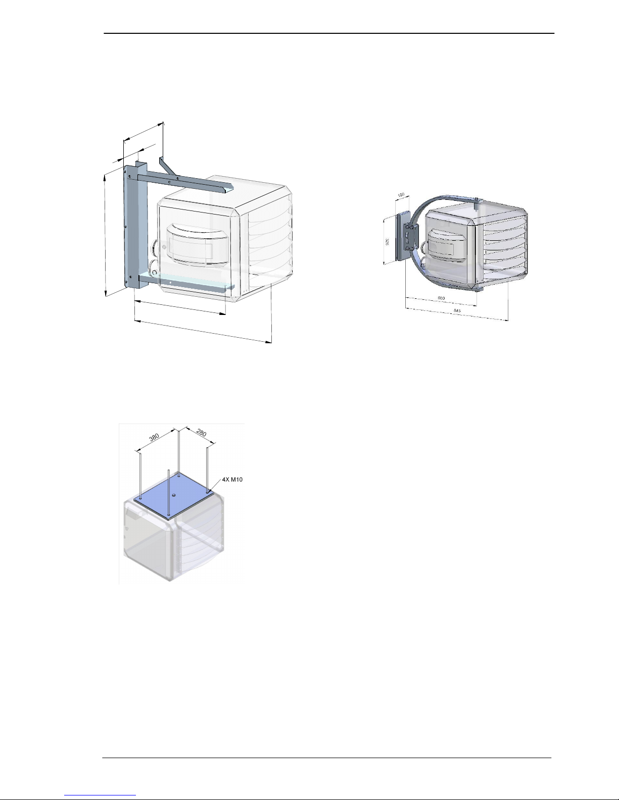
Available suspensions:
Standard bracket for type HR10 to 40 Design bracket type HR10 and 20
Horizontal horizontal
Suspension adapter for type HR10 and 20
M10 threaded bar
Page 9
Instructions condensing Air heaters type HR
Page 9/31
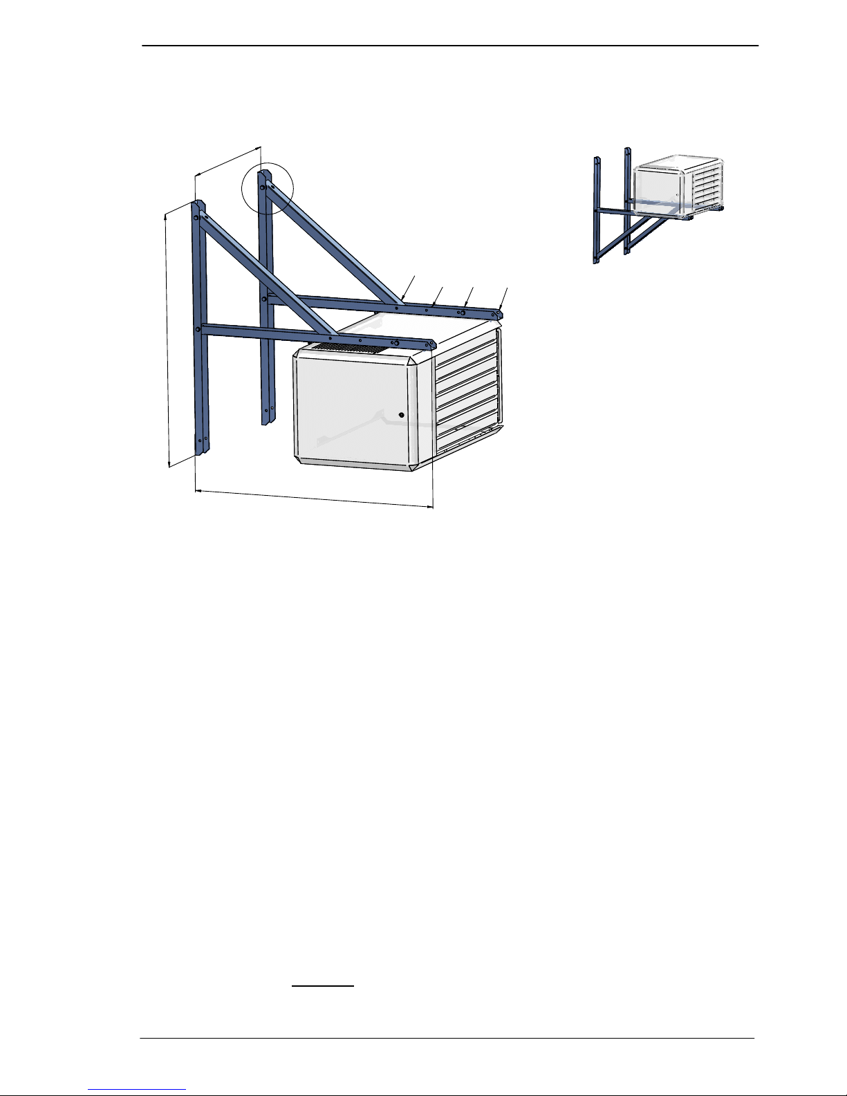
Wall console set HR30 up to 120
Art. Nr. : GA8580
1
2
0
0
1
2
0
0
S
e
e
i
n
s
t
a
l
l
a
t
i
o
n
m
a
n
u
a
l
45°
15° & 30°
Horizontal
15°
30°
45°
Horizontal
6.2 Gas connection
The gas supply line has to meet the national valid requirements and possibly the local
requirements of the building inspector, police or fire brigade. (In GB it must comply with Gas
Engineers publication UP-1 and UP-2 together with BS 6891.
A manual isolation valve in the supply line must be placed within reach of the heater, and all gas
lines must be mounted without any mechanical tension.
When testing the supply lines with pressures above 60 mbar, this manual valve at the heater
must be closed.
The working and standing supply pressure must be a minimum of 17 mbar, and a maximum of
30 mbar ,measured at the inlet pressure nipple of the gas control in the heater .
6.3 Electrical connection
6.3.1 230Vac supply
The installation must comply with local and national requirements, ( as well as IEE regulations)
The unit heater is delivered completely wired internally, where controls of any type are to be
added (e.g. room thermostat) , the relevant wiring diagrams must be followed to. Never use a
room thermostat to interrupt the electrical supply to the heater!
Make provisions to completely isolate the heater for maintenance purposes. This can be an
isolation switch (min.3mm contact opening gap) , a power plug or a non-switched fuse spur.
The wiring diagram for the heater can be found towards the end this manual.
The supply is 230Vac. with earth
. The control circuit is a two wire low voltage Argus-link bus
communication.
HR30 - 60
HR30 - 60
HR30 - 120 HR30 - 120
Page 10
Instructions condensing Air heaters type HR
Page 10/31
6.3.2 Room thermostat
The heater can only be controlled by special modulating Winterwarm room thermostats:
The Multi Therm Comfort; modulating digital clock thermostat with optimiser. It can control 1 to
8 air heaters HR10 up to HR60 or 1 to 4 air heaters HR80 up to 120.
The Multi Therm Standard; modulating digital thermostat. It can control 1 to 8 air heaters
HR10 up to HR60 or 1 to 4 air heaters HR80 up to 120.
The Interface printboard; special designed interface module for connecting the air heaters with
Building Mangagement Systems. (0-10V (modulating input) signal, high/low signal,
external reset and other different in and outputs.
ON/OFF thermostat
The heater can not be controlled with a simple on/off thermostat.
In all cases the communication between heater and thermostat is based on a two wire, lowvoltage connection. In the appliance the wire for the thermostat has to be connected to
connection 4 and 5 (see also electrical wiring diagram) Attention: This also needs a change in
the settings on the print board, see chapter 11
When mounting the thermostat, take attention to the following items:
• Mount the thermostat in a place where the air can circulate free pass the thermostat. Take
notice that the sun does not shine directly upon the thermostat (in the winter). Do not
place the thermostat on a cold wall. Place the thermostat on an inner wall free from
draught.
Never place the thermostat within the throw of the heater.
6.3.3 Thermostat cable
In all cases the communication between the heater and the thermostat is based on a two wire,
low-voltage connection. In the appliance the wire for the thermostat has to be connected to
connection 4 and 5 (see also electrical wiring diagram).
Cable specification: signal cable, 1x2x0,8 (shielded and twisted)
Maximum length 250m.
If the cable is chosen too thin, the signal will become too poor. If the cable is not shielded and
twisted the signal might become disturbed in an EMC unfriendly environment.
Keep the thermostat cable separated from mains cables. Connect the earth shield of the cable
only to the earth terminal in the heater.
If these guidelines are not followed it may result in malfunction of the installation or worse, it
could damage the thermostat or the electronics in the heater.
Never mount the thermostat near aerials of internal communication networks.
These emit radiation that could lead to disturbance of the thermostat. Always keep
some meters distance.
6.3.4 Fuses
On the heater control HC there are two fuses. See electrical wiring diagram.
F1 and F2 are in the power supply of the heater. Replace the fuse only by a fuse of the same
type, 5AT
Page 11

Instructions condensing Air heaters type HR
Page 11/31
6.4 Air intake / combustion products discharge
Check for compliance with local / national regulations.
Only the described flue material may be used. This goes for the roof or wall terminal and also
for the piping between the heater and the terminal. Only so the installation is approved.
Always connect a roof terminal for condensing appliances, otherwise condensate can form ice
in the winter on the terminal.
In some cases the roof terminal has to be at least 0,5m above roof level (local regulations).
6.4.1 Flue material
It is only allowed to use CE marked flue material from the manufacturer Muelink &
Grol (M&G) and Burgerhout, type Alu-fix temperature class minimum T120.. These
Flue systems can be bought at your supplier.
Only use one flue pipes from the same diameter as the flue spigots on the heater.
Different manufacturers have different connections systems from the flue pipes. It
is not allowed to combine systems from different manufacturers.
6.4.2 Flue terminals
Only the flue terminals that are provided with the heater may be used. These
terminals are certified together with the heater.
The following terminals are allowed:
HR10-60
- Concentric roof terminal type M&G Skyline 80-80 article: IA8214
• for h>0,5m above roof IA8217
- Concentric wall terminal type M&G HR80-80 article: IA8216
HR80-120
- Concentric roof terminal type M&G 130-130 HR article: IA8307
- Concentric wall terminal type M&G 130-130 HR article: IA8314
6.4.3 Mounting
Follow the mounting instructions for the flue and air intake materials
enclosed in the packaging of those systems.
Not following those instructions, for example not the correct fixation,
can lead to dangerous situations. Flue leaks can lead to physical
injuries. Always check the flue ways on tightness.
Condensate in the flue system
The During heating, condensate is formed in the discharge system. This condensate must flow
back into the heater. Therefore the flue discharge pipes have to be mounted in such a way that
the inclination of the pipes will result in the condensate flowing into the heater (minimum
inclination 50mm per meter).
When the condensate flows back from a stainless steel or plastic flue system into the heater, a
separate condensate drain should be mounted before the aluminium flue exit from the heater.
6.4.4 Combustion air intake
Single wall, ridged, aluminium, stainless steel, plastic air tight and should withstand corrosion.
To avoid accumulation of water into the supply pipes, they should also be mounted with an
inclination towards the heater.
6.4.5 Maximum flue length
The maximum pressure drop in either the air supply pipe, or the flue pipe ,must not exceed 9
metres straight pipe , excluding the terminal. Whenever bends are used the pressure drop is
greater and therefore a 90° bend will count as 2 metres and a 45° bend as 1 metre. All flue
Page 12

Instructions condensing Air heaters type HR
Page 12/31
575
1370
O
125
80
O
HOH 110
max 300
135 610
O
125
80
HOH 110
HR10 up to 60
horizontal discharge art.: IA8216
HR10 up to 60
vertical discharge: art.: IA8214
roof distance >0,5m: IA8217
pipes must be of the same diameter as the flue spigots on the heater, and all flue joints must be
sealed. For further information regarding the flue system please contact your reseller.
6.4.6 Flue terminals
In case of a vertical flue terminal in some cases the, the flue terminal should be at least 50cm
above the roof (local regulations). Take also distance into account with air intake openings to
the building. (national or local regulations)
The following flue terminals are allowed:
1775
O
200
990
O
130
HOH 225
max.300
300 690
HOH 225
O
130
O
200
HR80 up to 120
horizontal discharge
art.: IA8314
HR80 up to 120
vertical discharge
art.: IA8307
Page 13

Instructions condensing Air heaters type HR
Page 13/31
6.5 Condensate discharge
The condensate discharge pipe is on the bottom of the heater. The separate delivered siphon
has to be connected to the condensate Ø40mm PVC pipe. On the siphon a pipe Ø 40mm can
be mounted. The discharge system after the sifon has to be minimum Ø25mm and mounted
with an inclination to the sewer. The advised inclination should be minimum 30mm per meter.
The horizontal length should not exceed 5 meter.
The condensate should connected according to local and national regulations. Do not let the
condensate drip on the roof or roof edge outside the building, dangerous ice can be formed in
the winter. Condensate should be drained away to the sewer.
The condensate outlet from the heater should never be closed.
Protect the condensate drain from freezing. Ice can also close the condensate drain.
To be sure that the condensate can always flow out of the heater, an extra siphon should be
mounted before connecting to the sewer.
When the condensate discharge system is placed the siphon has to be filled with water. This is
important because otherwise the flue gases can flow into the room where the heater is placed.
HR10 up to 120
Horizontal
!
Max. amount condensate rate:
HR10
HR20
HR30/35
HR40
HR50
HR60
HR80 HR100
HR120
Max. Condens l/h 2 3 4 6 8
Page 14

Instructions condensing Air heaters type HR
Page 14/31
7 Functioning of the unit
7.1 General
The unit can heat as well as ventilate. By using the temperature-sensor on the unit and the one
in the room-thermostat, the temperature-difference between the two in the room is monitored.
Should the difference become higher than a set value, due to the fact that warm air has
accumulated underneath the roof, the system-fan will start and push the warm air down, acting
as a de-stratification fan.
7.2 Heat demand
If the thermostat indicates heat demand, the following cycle will commence:
1. Pre purge: The electronic circuit board acknowledges the heat-demand and the premix
burner fan will start running for 30 seconds. Display print 1
2. Ignition: After 30 seconds of pre purge the electrode will spark for max. 5 seconds, the
gas valve is opened and the gas-air mixture will ignite. Display print 2
3. Burn: When the flame is detected Display print b. the unit will modulate to the desired
load after ca. 15 seconds. Depending on the given load, the system fan will start
modulating (step-less) as well. The air heater will always burn for a minimum of 4
minutes. This is to evaporate eventual condensation in the discharge system.
4. End of heat demand: When the heat demand ends, the burner will switch off and the
system fan will continue to run for ca. 3 minutes in order to cool the unit down (Display
print P).
The unit will try to ignite twice before lockout on flame fault.
In the case of flame failure during operation, the heater will attempt one restart.
When the heater is in lockout you see in the display intermittent an A1. On the display of the
room thermostat you see failure 1.
7.3 Delta-T-regulation (temperature controlled de-stratification fan)
In case there is no heat demand, the delta-T-regulation will be active.
When the temperature-difference between the sensor on the unit (the NTC) and the sensor in
the thermostat is bigger than the set value (factory setting standard 8°C), the system fan will
start, at a regulated speed, depending on the differential temperature difference. This operation
ensures an even temperature distribution throughout the building, thus acting as a fully
automatic variable de-stratification fan. Should this delta-T-regulation not be required, in the
Menu Program Settings on the room thermostat this regulation can be switched off. See user
manual of the special Winterwarm Room thermostat.
7.4 Summer ventilation
It is possible to let the ventilator run on a certain speed in the summer. Please follow the
instructions in the manual from the thermostat.
7.5 High limit protection
7.5.1 T max. Heat exchanger
The unit contains 2 temperature protections. The NTC thermostat monitors the air temperature
electronically. Should the temperature, in a first step, become too high, the burner will modulate
to the minimum input and the system fan will modulate to the maximum speed.
When the temperature still increases, the burner will switch off (on display you see intermittent
an E1). When the heat exchanger has been cooled to normal levels the burner will start
automatically.
Should the temperature increase to an unacceptable level, the heater stops (on the display you
see intermittent A2). Only after a manual reset the heater can start again. Manual reset can be
done on the electronic circuit board or with the special Winterwarm Room thermostat
Page 15

Instructions condensing Air heaters type HR
Page 15/31
7.5.2 T max. Flue gas outlet
For the application of plastic flue material on the HR heaters the maximum flue gas temperature
is monitored (Tflue < 120 °C). A temperature sensor in the flue outlet the heater monitors the
temperature of the flue. When the flue temperature is too high (Tflue > 110 °C), the burner
modulates its capacity to the minimum. When the temperature keeps rising, and reaches
115°C, the burner stops. When after an automatic restart the situation repeats itself the heater
will lock out. The error A7 will show in the display.
7.6 Flue Transport Supervision
The unit is provided with a pressure switch to control the transport of combustion air through the
heat exchanger. It checks in the pre purge phase if there is sufficient movement of combustion
air through the heat exchanger by measuring the pressure difference over the heat exchanger.
If the pressure difference is too low in the pre purge phase, default A9 will occur. This could
mean that combustion air is leaking from the heat exchanger and so the heat exchanger must
be checked on leakage.
7.7 Description heater control HC
The heater control HC controls the unit and communicates with the room thermostat.
Functions integrated in the heater control HC are:
-two wire communication with room thermostat
-spark igniting on burner
-ionisation flame guard on burner
-controlling the gas valve
-modulating the premixed fan and burner
-modulating the system fan
-guarding the temperature of the heat exchanger
-LED signals status of heater, heat demand: green, failure: red
-Status of heater on 8 segment display on heater control HC
-reset of heater
-service mode function
Page 16

Instructions condensing Air heaters type HR
Page 16/31
Lay-out print board
J2
Fuse 5AT
J4
J8
U11
S1 J12
J6
S2
S3
J9
T2
J15
J7
0
1
123 4
5 6 7 8
on
Argus vision
J2 Main power connection 230V
J4 Connection for gas valve and system fan
J6 Connection for room thermostat, appliance recognition and the status LED’s green and red
J7 Earth burner
J8 Not used
J9 Premix- fan
J12 Connections for Temperature sensors
J15 Ionisation selector
F1 & F2 Fuses 2x 5AT
U11 Status display
S1 Reset service button
S2 Micro switch heater no. Standard 1 to “on”
S3 Power supply thermostat when S2 nr1 to “on” then S3 op 1 else S3 to 0
T2 Ignition transformer, connection for igniter
8 Putting into operation and adjustment
8.1 General
Prior to packaging, each unit is checked in detail on safety and well functioning. It is a.o.
adjusted to the right efficiency of combustion. In general, the heater does not need to be
adjusted after installation, only a check of well functioning is necessary by a competent person.
Also obtain a flue gas analysis and record it for later reference.
Use only a calibrated instrument !
The CO2 value may be adjusted if necessary, only do this in case it turns out that the CO2
value is not correct. Do not ever turn injudiciously the adjusting screws!
Adjustment of the gas control without a supporting flue gas analysis will invalidate the warranty.
Once the unit is installed according this manual, the unit can be put into operation. Make sure
the gas pipe is clean, gastight and free from air.
Switch on the electric supply with the maintenance-switch, and open the door in order to be able
to observe the first start-up and so become familiar with the functioning of the heater.
Should the gas line not be purged correctly the heater will attempt to start twice before going
into a lock-out condition. Manual reset is necessary in that case.
Do not forget to instruct the end user about a safe use of the heater (presence of gas, place of
the manual gas valve !), the operation of the heater (lock-out indication and reset) and about the
necessary maintenance. This manual must be left with the end user.
Page 17

Instructions condensing Air heaters type HR
Page 17/31
8.2 Start by using the service-button
Press the service-button once for 10 seconds, and the unit will commence the ignition-cycle; (30
sec pre-purge, ignition, 15 sec flame stabilise, modulating operation) The burner will then start
on minimum load Display print L/b . By pressing the service-button again, the burner will go
to maximum load. Display print H/b
Pressing the service-button for a third time will put the unit into normal operation. (depending if
there is heat demand from the room thermostat).
8.3 Start by using the thermostat
Put the thermostat in the highest position. The start sequence is always the same as 8.2.
8.4 To simulate a lock out condition
Close the manual gas supply valve. The heater will go to lock-out after a restart attempt. The
display on the electronic circuit board shows [
A 1
]. The red LED will light as well. Check also
the function of the reset button (with gas valve open again), and observe if the heater starts
smoothly.
Display on the print board
0
stand-by Stand-by
1
Pre-purge System checks and 30 sec pre purge of the burner fan
2
Ignition The ignition electrode sparks 5 sec. and the gas valve opens,
within 5 sec flame detection should occur.
b
Burn After 15 sec stabilisation time, the heater will modulate to the
desired power. The heater will remain burning minimum 4
minutes.
P
Post purge The heater will cool the heat exchanger for 3 minutes, and the
premix fan will post purge for 1 minute.
F
Summer
ventilation
The system fan is running on the summer ventilation mode
F
Blinking
Delta-T-regulation The system fan is running on low position on Delta-T-
regulation
L/1/2
/
…
Blinking
Service Low The heater is running on the service mode. When the heater
burns, the heater will run on minimum power.
H/1/2
/
…
Blinking
Service High The heater is running on the service mode. When the heater
burns, the heater will run on maximum power.
Page 18

Instructions condensing Air heaters type HR
Page 18/31
9 Adjusting the gas-control
In principle, it is not necessary to adjust the gas control after putting the unit into operation.
In case it needs to be adjusted, (e.g. after
fitting a new one), this must be done only by
a qualified person. Only use calibrated
instruments ! A poor adjustment can lead
to overheating and / or production of the
poisonous carbon monoxide !.
There are two screws to adjust the gas
control, the Offset adjuster and the Ratio
adjuster.
The Offset adjuster is used in Low fire. The Ratio adjuster is used in High fire.
Put the heater into operation at high fire by pressing the service button first 10 seconds and
press again shortly. You see on display H/b.
If the heater does not ignite while sparking, you can, if necessary, close the air-openings of the
coloured ring on the gas-air mixer with thumb and forefinger during ignition. The mixture will
become richer and will ignite more easily.
Look for the correct CO2 values in the table with technical data.
Readjust the CO2 when the deviation is more then 0,3%
1 Check the CO2 in High fire
Decrease CO2 turn the Ratio adjuster to the right (less gas).
Increase the CO2 turn the Ratio adjuster to the left (more gas).
2 Then check the CO2 in Low fire. The CO2 in low fire is lower then the high fire CO2.
Decrease the CO2 turn the Offset adjuster to the left.
Increase the CO2 turn the Offset adjuster to the right
After adjusting the CO2 in Low fire, return to high fire, and Readjust the CO2 with the Ratio
adjuster.
Then return to Low fire again and eventually readjust the CO2 with the Offset adjuster.
Repeat these steps until both values are oké.
Never forget to check the CO (carbon monoxide ) production of the heater!!! Too much CO
means mostly that the mixture is too rich. CO value should always be below 100 ppm.
HR80, 100 & 120 CO2 adjustment:
Check respectively at high and low level first heater 1 and adjust if necessary, then Heater 2
and adjust if necessary after this check then both heaters together.
10 Problem solving
10.1 General
When it turns out that the problem is not caused by the external circumstances (i.e. no electric
supply power or no gas), please take the following instructions into account. Please remember
the built in waiting times of the heater (do not react too soon!) and the signals of the LEDs and
the code on the display on the electronic circuit board.
Offset adj.
Ratio adj.
P out
P offset
P in
Page 19

Instructions condensing Air heaters type HR
Page 19/31
To simplify the investigation of the failing heater please check first:
• Check the fuses as well as the wires and plugs in the heater for possible loose contacts.
• In a heat-demand situation, the green LED on the heater must light up.
• In a failure situation, the red LED on the heater must light up, if so, reset.
• Use first the service-button to put the heater in run mode, try later the room thermostat.
Volatile lock out Can only be reset by hand
A/0
Blinking
Internal failure Print board defective
A/1
Blinking
No Flame Within 5 sec flame, then flame failure: Case 1:
No flame: Case 2
A/2
Blinking
Exchanger too hot Heater stops on temperature heat exchanger too hot. Case 3
A/3
Blinking
Sensor error Temperature sensor on heat exchanger error. Case 4
A/4
Blinking
Too many flame
failures
Too many flame failures on ionisation; Case 1, 5
A/5
Blinking
Internal error Print board defective
A/6
Blinking
Safety relays Safety relay failure Case 10
A/7
Blinking
Flame Flame detection when there should not be a flame or
The flue gas temperature sensor detects an error condition,
case 12.
A/8
Blinking
Burner fan Burner fan dos not run; Case 6
Burner fan runs; Case 7
A/9
Blinking
Pressure switch Insufficient air transport over the heat exchanger, Case 11
Non volatile lockout Will disappear when the error is cleared.
E/0
Blinking
Internal defect Print board defective
E/1
Blinking
1e temperature
safety
Heater stops on temperature heat exchanger too hot. When
heater is cooled down the heater will restart. Case 3
E/2
Blinking
Selection
resistance
Heater recognition does not work Case 8
E/3
Blinking
Selection
resistance
Heater recognition does not work Case 8
E/9
Blinking
Reset error Too many switches on reset button Case 9
Case 1: Within 5 sec flame, then flame failure.
• The flame is not detected. Check the ignition cable and electrode. (cable resistance 1K
ohm
• The heater has electrically a poor earth.
• The print board is defective.
Page 20

Instructions condensing Air heaters type HR
Page 20/31
Case 2:
• There is not enough gas pressure.
• The mixture of gas/air is poor, adjust the gas valve
• The gas valve does not open, check during ignition on 230V on the valve.
• Check whether the ignition electrode sparks, replace cable, electrode
Case 3: Heat exchanger too hot
• Check whether the system fan blows enough air.
• Check the setting of the gas valve, the heater may me overloaded.
Case 4: Temperature sensor on heat exchanger error.
• The sensor has internally 2 sensors. These differ too much. Measure the resistance from
each sensor, the resistance should be 20K at 25° en 25K at 20°. If the measured values
differ too much, replace sensor.
• Rotate the sensor ¼ turn. So the contact point is different on the sensor housing.
Case 5: Too many flame failures while burning
• The setting of the gas valve is not ok, adjust the gas valve
• The flue outlet is blocked
Case 6: The premix does not run
• Premix fan is Blocked or the wiring is bad
• Premix fan is defective
Case 7: The pre-mix fan runs, but not the correct speed.
• Check if the fan runs smoothly.
• Check the wiring.
Case 8: Selection resistance error
• Check the appliance recognition part, replace if necessary
Case 9: Reset button error
• Too many switches on reset button in a short period of time. These error will disappear
after some time, or if the main power is disconnected for a while.
Case 10: Safety relay error
• Plug J4 is not connected well, the bridge on connector 4 between 5 and 11 is not
connected well.
• Otherwise change print board.
Case 11: Insufficient air transport over the heat exchanger
• Check the pressure switch and the connections
• Check the heat exchanger for flue leakage
Case 12: the flue gas temperature sensor detects an error condition
• The flue gas temperature > 120 ° C insufficient air transport of the system fan or burner
adjustment is not correct, check CO2 and CO percentages.
• Loose or closed contact temperature sensor circuit, check the wiring
• The flue gas temperature sensor faulty, check the resistance value of the RG sensor
20 k at 25 °C and 25 k at 20 °C.
Heater does start, but shows other problems.
Heater ignites explosively, has often flame failures:
• Check the right setting of the gas control, the right CO2 setting is important for the
correct ignition.
• Check the ignition cable (1kOhm )
• Check the setting of the ignition electrode, the spark has to be formed between the
electrodes and not between the electrode and the burner.
Insufficient output
• The heat output of the heater will be insufficient if there is too much resistance in the
inlet- or outlet flue system. In this case the premix-burner-fan will be on full speed, but
because of the high resistance too little air is moved and therefore also too little gas. The
pressure in the outlet flue for example, will normally never be above 30 Pascal.
Page 21

Instructions condensing Air heaters type HR
Page 21/31
Non modulating system fan
• System fan (M1) does not start or does not vary in speed; Check first the functioning of
this fan by connecting it to 230 Volt. Check with a multi-meter if the different lower
tensions are secondary present on the transformer as well. The fuse could have failed. If
the motor and transformer are OK, the cause of the problem must be in the heater
control HC, as the heater control HC dictates the different voltages from the transformer
to the fan-motor. In that case, replace the heater control HC.
11 Maintenance / spare parts
The heater must be inspected and cleaned regularly (once a year) by a qualified installer who
understands this appliance.
This is all the more important as the circumstances are heavier, especially in case of dust,
humidity, high frequency of switching on/off etc.
Activities:
11.1 General inspection
• Check the overall condition of the installation. Check the heater, the thermostat, the wires
and the gas line.
11.2 Inspection of the heater
Before starting the inspection, switch off the electric power to the heater with the maintenanceswitch and close the manual gas valve.
• Take out the burner, complete with flange and pre-mix fan, by unscrewing the 6 off M6
socket screws and you have taken off the ignition and fan wires
• Check the heat exchanger from the inside for dirt and/or damage.
• Check the burner on damage and clean the ignition electrode if necessary . CAUTION: do
not twist the electrode out of shape!
• Check the air supply and the flue discharge.
• Clean eventual the inside of the heater with a vacuum cleaner.
• In case the heat exchanger is dirty on the outside, clean it with a soft brush. Never use a
steel wire brush!
• Clean the fan-grid with a vacuum cleaner and a brush.
• Put the burner back in (renew the gasket)
After this, check the heater on efficiency of combustion and adjust these if necessary
Check the heater operates correctly.
11.3 Ignition electrode
For the correct ignition of the burner it is important that the ignition electrode is adjusted right.
• The distance between the electrode and the burner should be 5.0 ±0.5 mm.
• The distance between the two electrodes should be 3.6 ±0.4 mm.
• Check the setting of the ignition electrode, the spark has to be formed between the
electrodes and not between the electrode and the burner.
5 ±0,5
3
.
6
±
0
,
4
Page 22

Instructions condensing Air heaters type HR
Page 22/31
12 Examples electrical installation
12.1 Thermostat cable
In all cases the communication between the heater and the
thermostat is based on a two wire, low-voltage connection. In
the appliance the wire for the thermostat has to be connected to
connection 4 and 5 (see also electrical wiring diagram).
Cable specification: signal cable, 1x2x0,8 (shielded
and twisted)
Maximum length 200m.
If the cable is chosen too thin, the signal will become too poor. If
the cable is not shielded and twisted the signal me become disturbed in an EMC unfriendly
environment.
Keep the thermostat cable separated from mains cables. Connect the earth shield of the cable
only to the earth terminal in the heater.
If these guidelines are not followed it may result in malfunction of the installation or worse, it
could damage the thermostat or the electronics in the heater.
Never mount the thermostat near aerials of internal communication networks.
These emit radiation that could lead to disturbance of the thermostat. Always keep
some meters distance.
12.2 Installation with modulating room thermostat
• Connect the heater to 230Vac
• Connect the thermostat to the terminals according to the
diagram. (terminal 4 and 5)
• On the print the switches S2 and
S3 need to be set as follows: S2
switch 1 at the ON position, and S3
at 1.
The change of these switches need to be performed without
power on the Heater, otherwise these settings take no effect.
12.3 Installation of more heaters on one
thermostat
One room thermostat can control 8 heaters. To connect
the heaters is very simple. The two wires for the
thermostat can be connected to heater one, from heater
one to heater two , from heater two to heater three etc.
etc. Connect always on terminal 4 and 5. See also the
diagram.
Standard factory setting: switch 1 “on”.
Each heater needs his own unique number to recognise
the heater by the room thermostat. The number of the heater can be set by the micro switch on
the heater control HC in the heater. The number at the upper position of the switch is the given
number for that heater. Make sure that each heater has is own unique number. If more than one
heater have the same number the system does not work.
The change of these switches need to be performed without power on the Heater, otherwise
these settings take no effect.
1 2
5
43
Neutal
L (230V AC)
22°C
Thermostat (bus )
Installer
1 2
5
43
Neutal
L (230V AC)
22°C
Thermostat (bus )
Installer
1 2 3 4 5 6 7 8
ON
1
0
S3
S2
1 2 3 4 5 6 7 8
ON
1 2 3 4 5 6 7 8
ON
1 2 3 4 5 6 7 8
ON
Heater 1
Heater 2
Heater 3
0
1
S2
S3
0
1
0
1
Page 23

Instructions condensing Air heaters type HR
Page 23/31
Diagram for more heaters on one thermostat
1 2 543
Neutal
L (230V AC)
Heater 1
1 2 543
Neutal
L (230V AC)
Heater 2
1 2 543
Neutal
L (230V AC)
Heater 3
1 2 543
Neutal
L (230V AC)
Heater 8
22°C
Max. 8 Heaters
22°C
Heater 3
L (230V AC)
Neutal
3 4 521
Heater 2
L (230V AC)
Neutal
3 4 521
Heater 1
L (230V AC)
Neutal
3 4 521
1 2 3 4 5 6 7 8
ON
in heaters:
micro switch on printboard.
1 2 3 4 5 6 7 8
ON
1 2 3 4 5 6 7 8
ON
Important:
Whem m ore heaters on one thermostat, each next
heater must have its own num ber (2 til 8).
Only in heater nr 1 S3 to ON, other heaters S3 to 0.
Do not change clamb 4 with 5 between the heaters.
Communication bus:
2 wires; low voltage
Heater 1
Heater 2
Heater 3
0
1
S2
S3
0
1
0
1
Page 24

Instructions condensing Air heaters type HR
Page 24/31
Installation diagram one room thermostat for more HR80, 100 & 120
L N L NL N
S3
S2
S3
S2
L N
L N
L N
S3
S2
S3
S2
22°C
1 2 3 4 5 6 7 8
ON
0
1
S2
S3
1 2 3 4 5 6 7 8
ON
0
1
1 2 543
L (230V AC)
Neutal
1 2 543
L (230V AC)
Neutal
S2
S3
1 2 3 4 5 6 7 8
ON
0
1
1 2 3 4 5 6 7 8
ON
0
1
S2
S2
S3
S3
Heater 1
Heater 2
Heater 3
Heater 4
HR80, 100 of 120
Module 1
HR80, 100 of 120
Module 2
1
2
3
4
max. 4 modules /
max. 8 heaters
Ruimtethermostaat
MTS, MTC of Interface print
At the first HR80, 100 of 120 the dipswitches S2 en switch S3 are been set standard ex works:
Heater 1: S2 1 en S3 1
Heater 2: S2 2 en S3 0
In case of more heaters on 1 room thermostat (max. 4 HR80, 100 of 120 heaters) the
dipswitches S2 en switches S3 has to been set on:
Heater 1: S2 1 en S3 1
Heater 2 up to 8: S2 resp. 2 up to 8 en S3 0.
Page 25

Instructions condensing Air heaters type HR
Page 25/31
13 Electrical diagram
HR10 - 60
N
L
1
2
3
1
2
3
J2
341 9 10 122 7
5
11
6
8
J4
1
2
3
4
1
2
3
4
5
6
1
5
4
2
3
M2
1
5
2
6
3
7
4
8
-T
20K@25°C
-T
20K@25°C
-T
20K@25°C
5 61211 13 14
4
5
22°C
4
7
M1
T2
J6
J12
J9
1 2 3 1098
166HC
Get: MW
Date: 10-06-2009
Auth:
Ver:a
Title:
Nr.:
R108
HR-series 10... 60
J7
F2
F1
2 x 5AT
AirTemperature
sensor on
heater
Thermostat (bu s)
LED 1
red
(opt.)
LED 2
green
(opt)
green/yellow
blue
brown
black
green/yellow
grey
red
green/yellow
blue
black
white
yellow
orange
white
puple
green/yellow
blue
black
Neutal
Installer
blanc
white
red
green
GB
1 2 3 4 5 6 7 8
ON
10
S3
S2
R2 R3
Micro switches S2 standard 1 t o ON, and S3 to 1.
When m ore heaters on one thermostat, each next heater
must have its own number (2 til 8).
Only in heater nr 1 S3 to 1, other heaters S3 to 0.
Temperature
sensors on heat
exchanger
green
yellow
brown
white
white
brown
Apliance
recognition
VentilatorVentilator
gasvalve
Burner ventilator
1 2 3 4 5 6 7 8
ON
10
S3
S2
ON / OFF setting
2
5
4
1
-T
20K@25°C
-T
20K@25°C
flue/ abgas/ fumée
/rookgas sensor
12 11
dP
Air pressure
switch
1
2
5
43
L (230V AC)
22°C
Neutal
Thermostat (bus)
Installer
12
11
Shield
Page 26

Instructions condensing Air heaters type HR
Page 26/31
HR80-120
Get: MW
Date: 07-2014
Auth:
Ver:a
Title:
Nr.:
R136
HR-series 80... 120
1 2 3 4 5 6 7 8
ON
10
S3
S2
N
L
1
2
3
1 2 3
J2
341 9 10 122 7
5
11 6
8
J4
1 2 3 4
1
2
3
4
5
6
1
5
4
2
3
M1.2
1
5
2
6
3
7
4
8
-T
20K@25°C
-T
20K@25°C
-T
20K@25°C
5 61211 13 144
7
M1.1
T2
J6
J12
J9
1 2 3 1098
Control unit 1
166HC
J7
F2
F1
2 x 5AT
R2 R3
254
1
-T
20K@25°C
-T
20K@25°C
rookgas sensor
12 11
dP
1
2 3
J2
341 9 10 122 7
5
11
6
8
J4
1
2 3 4
1
2
3
4
5
6
1
5
4
2
3
M2.2
1
5
2
6
3
7
4
8
-T
20K@25°C
-T
20K@25°C
-T
20K@25°C
5 61211 13 144 7
M2.1
T2
J6
J12
J9
1 2 3 1098
Control unit 2
166HC
J7
F2
F1
2 x 5AT
R2 R3
25 4
1
-T
20K@25°C
-T
20K@25°C
flue/ abgas/ fumée
/rookgas sensor
13 14
dP
5
4
22°C
1 2 3 4 5 6 7 8
ON
10
S3
S2
1 2543
L (230V AC)
22°C
121113 14
GB
Air temperature
sensor on the
heater
LED 1
red
(opt.)
LED 2
green
(opt)
green/yellow
blue
brown
black
green/yellow
grey
red
green/Yellow
blue
black
white
yellow
orange
green/yellow
blue
black
blanc
white
red
green
Temperature
sensor on the
heat exchanger
Appliance
recognition
Ventilator 1
gas valve 2
Burner ventilator
Ait pressure
switch
LED 1
red
(opt.)
LED 2
green
(opt)
green/yellow
blue
brown
black
green/yellow
grey
red
green/yellow
blue
black
white
yellow
orange
green/yellow
blue
black
blank
white
red
green
wit
brown
appliance
recognition
Ventilator 2
gas valve 2
Burner ventilator
Air pressure
switch
Thermostat (bus)
Module 1: micro switch S2 standard 1 to ON, and S3 to 1.
Module 2: microswitch S2, 2 to ON and S3 to 0
In case of more heaters on one thermostat, each next
heater must have is own number
(3 till 8)
.
only in module nr 1 S3 to 1, other modules S3 to 0.
Neutal
Installer
Neutal
Thermostat (bus)
Schield
Air temperature
sensor on the
heater
Temperature
sensor on the
heat exchanger
Page 27

Instructions condensing Air heaters type HR
Page 27/31
14 Exploded views and spare parts
14.1 Spare parts
No.
HR10 HR20 HR30 HR40 HR50 HR60
1
Burner natural gas GA3206 GA3207 GA3208 GA3208 GA3210 GA3212
1
Burner propane GA3242 GA3244 GA3246 GA3248 GA3250 GA3252
2 Ignition / ionisation set GA3460 GA.3460 GA3460 GA3460 GA3460 GA3460
5
Premix fan
Torin DSB126-15
GX4522 GX4522 GX4522 GX4522 GX4522 GX4522
6
Gas valve
SIT SIGMA 848
GA3000 GA3000 GA3000 GA3000 GA3000 GA3000
7 System fan IX4201 IX4201 IX4201 IH4206 GX4207 GX4207
8
Control unit
Argus 0166-HC)
GA5902 GA5902 GA5902 GA5902 GA5902 GA5902
9 Pressure switch GX3932 GX3932 GX3932 GX3932 GX3932 GX3932
10 NTC sensor set GA3928 GA3928 GA3928 GA3928 GA3928 GA3928
11 Gasket set GA6730 GA6730 GA6731 GA6731 GA6731 GA6731
12 Burner isolation GA6700 GA6700 GA6704 GA6704 GA6704 GA6704
13 Flue sensor HR GX3925 GX3925 GX3925 GX3925 GX3925 GX3925
No.
HR80 HR100 HR120
1
Burner natural gas GA3208 GA3210 GA3212
1
Burner propane GA3254 GA3256 GA3258
2 Ignition / ionisation set GA3460 GA.3460 GA3460
5
Premix fan
Torin DSB126-15
GX4522 GX4522 GX4522
6
Gas valve
SIT SIGMA 848
GA3000 GA3000 GA3000
7 System fan IH4206 GX4207 GX4207
8
Control unit
Argus 0166-HC)
GA5902 GA5902 GA5902
9 Pressure switch GX3932 GX3932 GX3932
10 NTC sensor set GA3927 GA3927 GA3927
11 Gasket set GA6731 GA6731 GA6731
12 Burner isolation GA6704 GA6704 GA6704
13 Flue sensor HR GX3925 GX3925 GX3925
Page 28

Instructions condensing Air heaters type HR
Page 28/31
1
2
5
6
8
7
10
10
13
9
11
11
12
11
14.2 Exploded view HR10-20
Page 29

Instructions condensing Air heaters type HR
Page 29/31
14.3 Exploded view HR30-60
1
2
5
6
7
8
9
10
10
11
13
11
12
11
Page 30

Instructions condensing Air heaters type HR
Page 30/31
1
1
2
2
5
5
6
6
8
8
7
7
10
10
10
10
13
13
9
11
11
12
11
12
11
11
11
9
14.4 Exploded view HR80-120
15
Page 31

Instructions condensing Air heaters type HR
Page 31/31
CE Certificate & Declaration
 Loading...