

Winterwarm HR10, HR20, HR30, HR60, HR80 Instruction Manual
...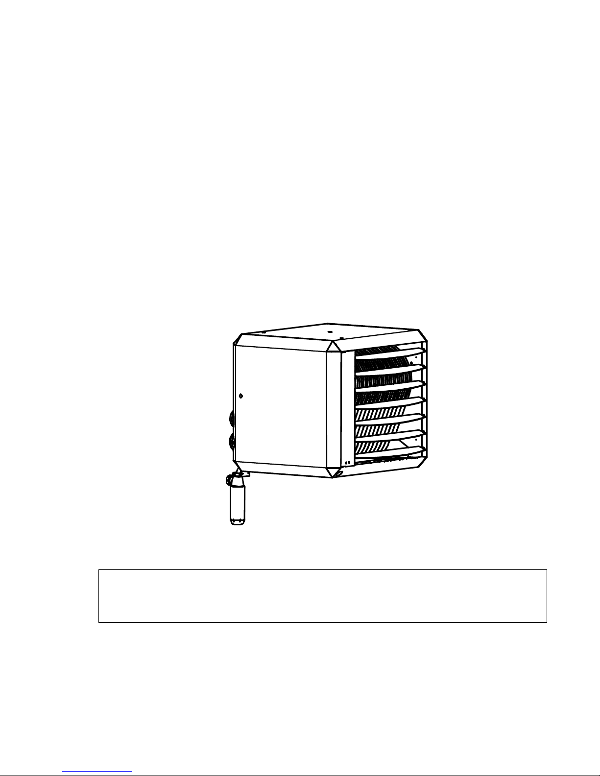
INSTRUCTION MANUAL
PREMIX UNIT AIR HEATER
TYPE HR
Production from 2014
THIS DOCUMENT MUST ABSOLUTELY BE READ BEFORE STARTING THE
INSTALLATION.
INSTRUCT USER AND LEAVE THIS DOCUMENT WITH HEATER FOR
REFERENCE.
Instruction manual version GB 109g
Heaters for GB
date: 01-02-2018
heaters for natural gas G20 and Propane

Instructions condensing Air heaters type HR
Page 2/31
1 Introduction:
This installation and user manual is produced specifically for the gas, electrical and mechanical
installer , it also gives instructions how to use and maintain the heater.
2 Content:
Page
1 INTRODUCTION: 2
2 CONTENT: 2
3 GENERAL 3
3.1 G
UARANTEE
3
4 APPLICATION RESTRICTIONS 3
4.1 PRE-
CHECK
3
4.2 P
ROTECTION DEGREE
4
5 TECHNICAL DETAILS: 4
6 INSTALLATION 7
6.1 P
OSITIONING
7
6.2 G
AS CONNECTION
9
6.3 E
LECTRICAL CONNECTION
9
6.4 A
IR INTAKE / COMBUSTION PRODUCTS DISCHARGE
11
6.5 C
ONDENSATE DISCHARGE
13
7 FUNCTIONING OF THE UNIT 14
7.1 G
ENERAL
14
7.2 H
EAT DEMAND
14
7.3 D
ELTA
-T-
REGULATION (TEMPERATURE CONTROLLED DE-STRATIFICATION FAN
) 14
7.4 S
UMMER VENTILATION
14
7.5 H
IGH LIMIT PROTECTION
14
7.6 F
LUE TRANSPORT SUPERVISION
15
7.7 D
ESCRIPTION HEATER CONTROL
HC 15
8 PUTTING INTO OPERATION AND ADJUSTMENT 16
8.1 G
ENERAL
16
8.2 S
TART BY USING THE SERVICE-BUTTON
17
8.3 S
TART BY USING THE THERMOSTAT
17
8.4 T
O SIMULATE A LOCK OUT CONDITION
17
9 ADJUSTING THE GAS-CONTROL 18
10 PROBLEM SOLVING 18
10.1 G
ENERAL
18
11 MAINTENANCE / SPARE PARTS 21
11.1 G
ENERAL INSPECTION
21
11.2 I
NSPECTION OF THE HEATER
21
11.3 I
GNITION ELECTRODE
21
12 EXAMPLES ELECTRICAL INSTALLATION 22
12.1 T
HERMOSTAT CABLE
22
12.2 I
NSTALLATION WITH MODULATING ROOM THERMOSTAT
22
12.3 I
NSTALLATION OF MORE HEATERS ON ONE THERMOSTAT
22
Instructions condensing Air heaters type HR
Page 3/31
13 ELECTRICAL DIAGRAM 25
14 EXPLODED VIEWS AND SPARE PARTS 27
14.1 S
PARE PARTS
27
14.2 E
XPLODED VIEW
HR10-20 28
14.3 E
XPLODED VIEW
HR30-60 29
14.4 E
XPLODED VIEW
HR80-120 30
15 CE CERTIFICATE & DECLARATION 31
3 General
The premix unit air heater is provided with sophisticated control sequence to maintain a
comfortable room temperature and even air distribution.
It is paramount that that the installation and maintenance of this appliance are carried out by
qualified gas engineers, and strictly according to our instructions.
This is a condensing heater. This means a condensate water discharge system should be
installed according to local regulations. Never block this discharge.
3.1 Guarantee
The guarantee is invalidated when the air heaters are not installed in accordance with this
manual.
4 Application restrictions
Important!
The installation en maintenance of this air heater should be performed by an
authorized competent installer in accordance with this manual.
This appliance is not intended for use by persons (including children) with reduced physical,
sensory or mental capabilities, or lack of experience and knowledge, unless they have been
given supervision or instruction concerning use of the appliance by a person responsible for
their safety. Children may not play with this heater.
4.1 Pre-check
Before unpacking and installation, please check (i.e. on the data badge) if the heater is in
accordance with the order and if it is suitable for the local present provisions (gas type, gas
pressure, electrical supply etc.)
The Installation must comply with all applicable local and national standards.
The installation of the air heater must be in accordance with the relevant requirements of the
Gas Safety regulations (for example in GB; The Institute of Gas Engineers IGE UP-1 and 2),
building regulations and the IIE regulations also incorporating the gas safety (installation and
use) regulations. Other national and/or local regulations may apply (the Local Authority ,Fire
Officer and Insurers)
The competent installer must make sure the heater operates correctly and must instruct the
user about the safe operation of the heater.
A ventilation gap of 30 cm is required from the top and bottom of the heater to any flammable
materials.
If this heater is drawing its combustion air from within the room in where it is located, the
necessary combustion ventilation requirements must be followed for gas safety regulations.
The heater should not be installed in areas containing any corrosive or explosive vapours , in
high moisture or dust concentrations, at negative pressures or temperatures higher than 30°C ;
please consult Winterwarm or your supplier. The guarantee is then invalidated..
Instructions condensing Air heaters type HR
Page 4/31
Make sure that the warm air can be blown out freely. There should absolutely be (no possibility
of) materials within 5m from the front of the heater.
The heater has been tested in detail on safety and correct operating settings before leaving the
factory. It has been adjusted for the type of gas that is stated on the data badge. Should there
be any doubt , please contact the manufacturer.
4.2 Protection degree
The heater has a protection degree of IP20, this means for use in a dry and not very dusty
environment. This is also the case for the Winterwarm room-thermostat.
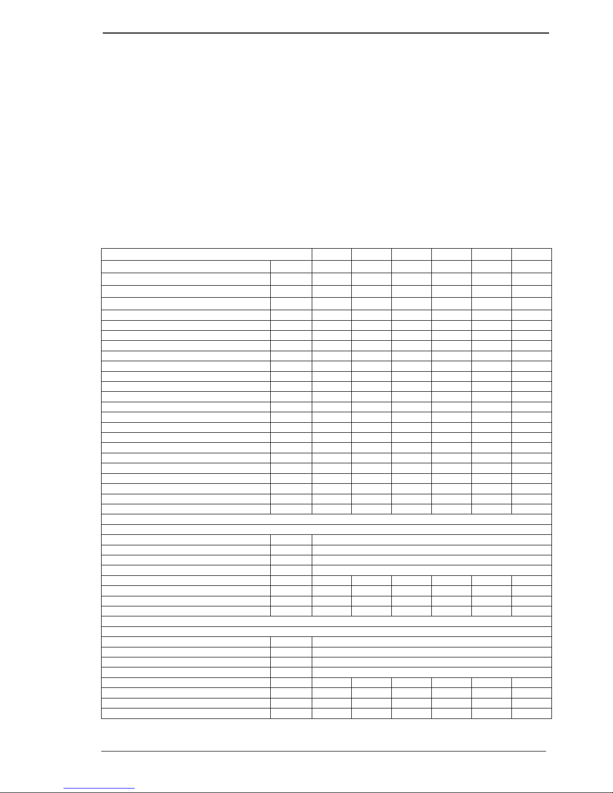
5 Technical details:
Type HR
10 20 30 40 50 60
Maximum nominal heat input (H.I.) kW 12,5 20,0 30,0 40,0 50,0 60,0
Minimum nominal heat input (H.I.) kW 4,0 6,0 9,0 12,0 15,0 18,0
Efficiency max. power % 96,0 96,0 96,5 97,0 96,5 96,6
Efficiency 30% power % 106,0 106,0 106,0 106,5 106,0 106,0
Maximum heat output kW 12,0 19,2 29,0 38,8 48,3 58,0
Minimum heat output kW 4,2 6,4 9,5 12,8 15,9 19,1
Max air output (warm) m3/hr 2.000 2.600 3.000 4.500 5.000 6.000
Throw horizontal (max) m 15 20 23 26 28 30
Gas connection G” ½” bin ½” bin ¾” bui ¾” bui ¾” bui ¾” bui
Electrical Voltage [50 Hz] V 230 230 230 230 230 230
Electrical power max. kW 0,250 0,250 0,250 0,450 0,450 0,600
Electrical power min.
kW 0,250 0,250 0,250 0,450 0,450 0,600
Electrical power standby
kW 0,004 0,004 0,004 0,004 0,004 0,004
Electrical current A 1,1 1,1 1,2 2,0 2,6 2,6
Emission efficiency, (ηs,flow) % 97,6 96,4 94,6 95,0 94,8 94,6
Seas. space heating efficiency % 90,4 90,1 88,7 89,9 89,2 89,4
NOx emission (GCV) mg/kWh 30 21 33 40 31 44
NOX class 5 5 5 5 5 5
Flue amount max. kg/hr 19,4 31,1 48,3 64,2 80,2 96,2
Thermostat bus system (low voltage) Ja Ja Ja Ja Ja Ja
Sound level (average @ 4 meter) dBA 45 45 45 47 48 49
Suspension height horizontal throw min. m 1,7 1,7 1,7 1,7 1,7 1,7
Flue length max. m 9 9 9 9 9 9
Weight m 45 50 75 85 105 110
Natural gas G20, heater version 3.3
Nominal supply pressure G20 mbar. 20
Supply pressure (min-max) G20 mbar. 17-25
Gas category Cat. I2H
Class Class. B23, C13, C33
Max gas consumption G20 m3/hr 1,3 2,1 3,2 4,2 5,3 6,3
CO2 High G20 % 9,5 9,5 9,2 9,2 9,2 9,2
CO2 Low G20 % 9,0 9,0 8,8 8,8 8,8 8,8
CO (@ 0%O2) mg/kWh 4 5 1 1 3 3
Propane, G31, heater version 3.4
Nominal supply pressure G31 mbar. 30-50
Supply pressure (min-max) G31 mbar. 25-50
Gas category Cat. I3P
Class Class. B23, C13, C33
Max gas consumption G31 kg/hr 1,0 1,6 2,4 3,2 4,0 4,8
CO2 High G31 % 10,7 10,7 11,0 11,0 11,0 11,0
CO2 Low G31 % 10,3 10,3 10,5 10,5 10,5 10,5
CO (@ 0%O2) mg/kWh 13 8 3 1 1 1
Instructions condensing Air heaters type HR
Page 5/31
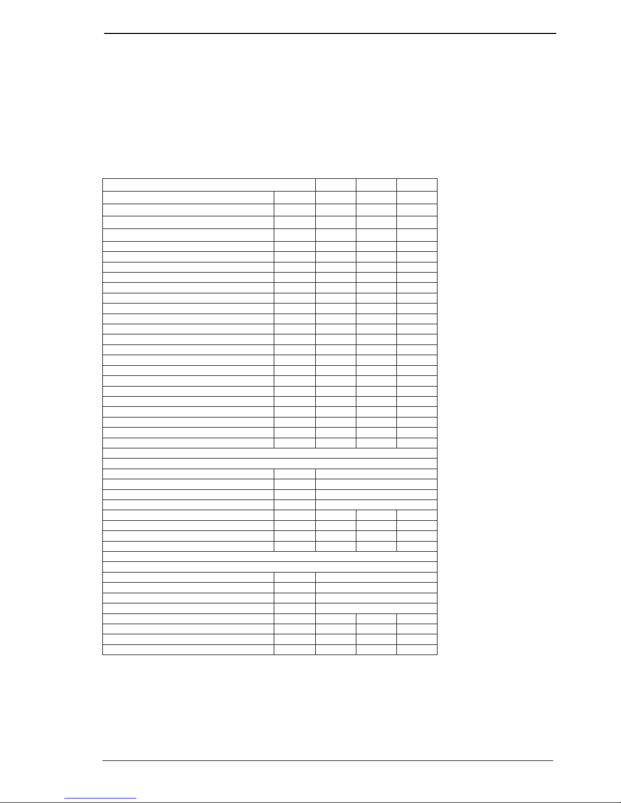
HR80, 100, 120
The HR80 & 100 & 120 heaters are respectively 2 x HR40, 50 & 60 heaters been placed on top
of each other in cascade in one casing with 1 gas connection, 1 combined air inlet, 1 combined
flue outlet, 1 electrical connection, 1 thermostat connection and 1 condensate drain. For the
proper functioning and to prevent interaction between the two burners, a gravity check valve
has been placed between the premix burner fan and the burner.
Please note that when more then only this heater is connected to one thermostat the micro
switches on the print boards in the heaters have to be set different.
See section 12.3 multiple heaters on 1 room thermostat.
Type HR
80 100 120
Maximum nominal heat input (H.I.) kW 80,0 100,0 120,0
Minimum nominal heat input (H.I.) kW 24,0 30,0 36,0
Efficiency max. power % 97,0 96,8 96,5
Efficiency 30% power % 105,0 105,0 105,0
Maximum heat output kW 77,6 96,8 115,8
Minimum heat output kW 25,2 31,5 37,8
Max air output (warm) m3/hr 8.500 10.000 12.000
Throw horizontal (max) m 30 30 33
Gas connection G” 1” int. 1” int. 1” int.
Electrical Voltage [50 Hz] V 230 230 230
Electrical power max. kW 0,900 1,000 1,050
Electrical power min.
kW 0,900 1,000 1,050
Electrical power standby
kW 0,010 0,010 0,010
Electrical current A 3,9 4,4 4,7
Emission efficiency, (ηs,flow) % 95,5 95,6 95,5
Seas. space heating efficiency % 88,8 89,0 89,1
NOx emission (GCV) mg/kWh 38 33 36
NOX class 5 5 5
Flue amount max. kg/hr 128,4 160,4 192,4
Thermostat bus system (low voltage) Ja Ja Ja
Sound level (average @ 4 meter) dBA 50 51 52
Suspension height horizontal throw min. m 1,7 1,7 1,7
Flue length max. m 9 9 9
Weight m 180 195 205
Natural gas G20, heater version 3.3
Nominal supply pressure G20 mbar. 20
Supply pressure (min-max) G20 mbar. 17-25
Gas category Cat. I2H
Class Class. B23, C13, C33
Max gas consumption G20 m3/hr 8,4 10,6 12,6
CO2 High G20 % 9,2 9,2 9,2
CO2 Low G20 % 8,8 8,8 8,8
CO (@ 0%O2) mg/kWh 1 3 3
Propane, G31, heater version 3.4
Nominal supply pressure G31 mbar. 30-50
Supply pressure (min-max) G31 mbar. 25-50
Gas category Cat. I3P
Class Class. B23, C13, C33
Max gas consumption G31 kg/hr 6,4 8,0 9,6
CO2 High G31 % 11,0 11,0 11,0
CO2 Low G31 % 10,5 10,5 10,5
CO (@ 0%O2) mg/kWh 1 1 1
Instructions condensing Air heaters type HR
Page 6/31
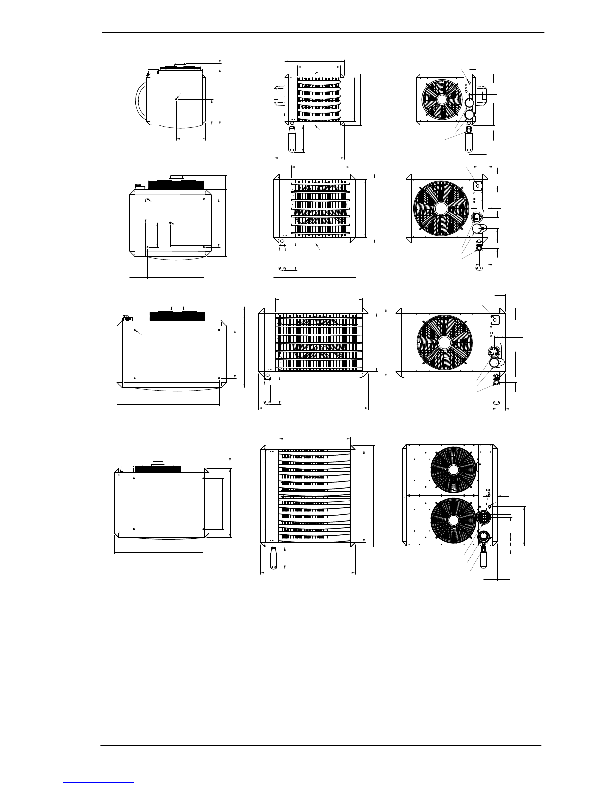
490 125
285
245
M10
420
495
420
680
M10
M10
100 110 85
65
65
85
35
O
40
IN O80
OUT O80
Gas 1/2"
Type 10 & 20
575
795
670
565
575
650 125
470
545
M10
4x M10
M10
115140 110
100
105
Gas 3/4" ext.
INO80
OUTO80
325
400
180
=
=
35
85
180 815
470
650 125
4X M10
565
670
1065
Gas 3/4" ext.
100
115
105
11014035
85
IN O80
OUT O80
O
40
O
40
Type 30 & 40
Type 50 & 60
280
280
280
840
815227
600
812 75
280
1115
1090
1195
840
87
462
11045
158
158
Gas 1" int.
Ø40
Type 80, 100 & 120
225
IN Ø130
OUT Ø130
Instructions condensing Air heaters type HR
Page 7/31
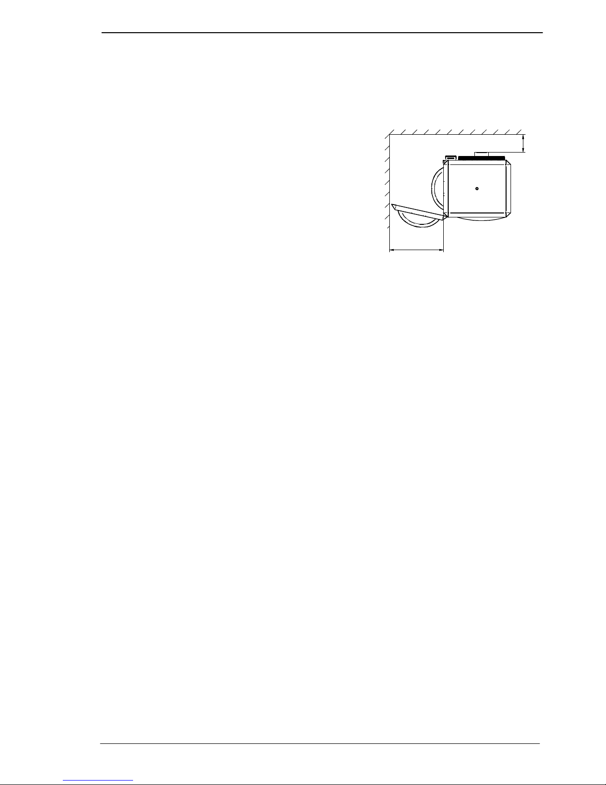
6 Installation
6.1 Positioning
• Check that the support is solid enough.
• The heater is designed as free hanging. The heater
should be able to blow the warm air free from any
ducting or obstacles. Also the air intake should be
free.
• Keep sufficient distance between the heater and any
obstruction , in connection with safety and access for
service and maintenance. Pay particular attention to
any flammable materials. Please take into account
the possibility to open the door of the heater for the
necessary service and maintenance work . Make
sure the air flow to and from the heater is unhindered. Any obstacles should be a minimum
of 5 metres away from the front of the heater.
• The heater can be installed horizontally or on an angle of maximum 45 degrees downwards.
• The heaters type 10 and 20 are provided with 2 off M10 threaded sockets as fixing points
(see the dimension diagram).
• The types 30 and 40 have in the middle a M10 socket and also 4 sockets on the top corners
of the heater
• The types 50 and 60 have on the top and bottom 4 M10 sockets. (see drawings)
• Use preferably the Winterwarm suspension kits.
• Make sure that after fitting, there is no mechanical tension on any connecting gas or electric
supplies.
• If the heater is installed with the air stream vertical downwards the maximum suspension
height is 8 meters. Otherwise the warm air will not reach the floor.
Attention:
See the application-restrictions in this manual (Chapter 4) for further installation restrictions.
min 250
10 t/m 30 min. 500 mm
40 t/m 60 min 660 mm
Instructions condensing Air heaters type HR
Page 8/31
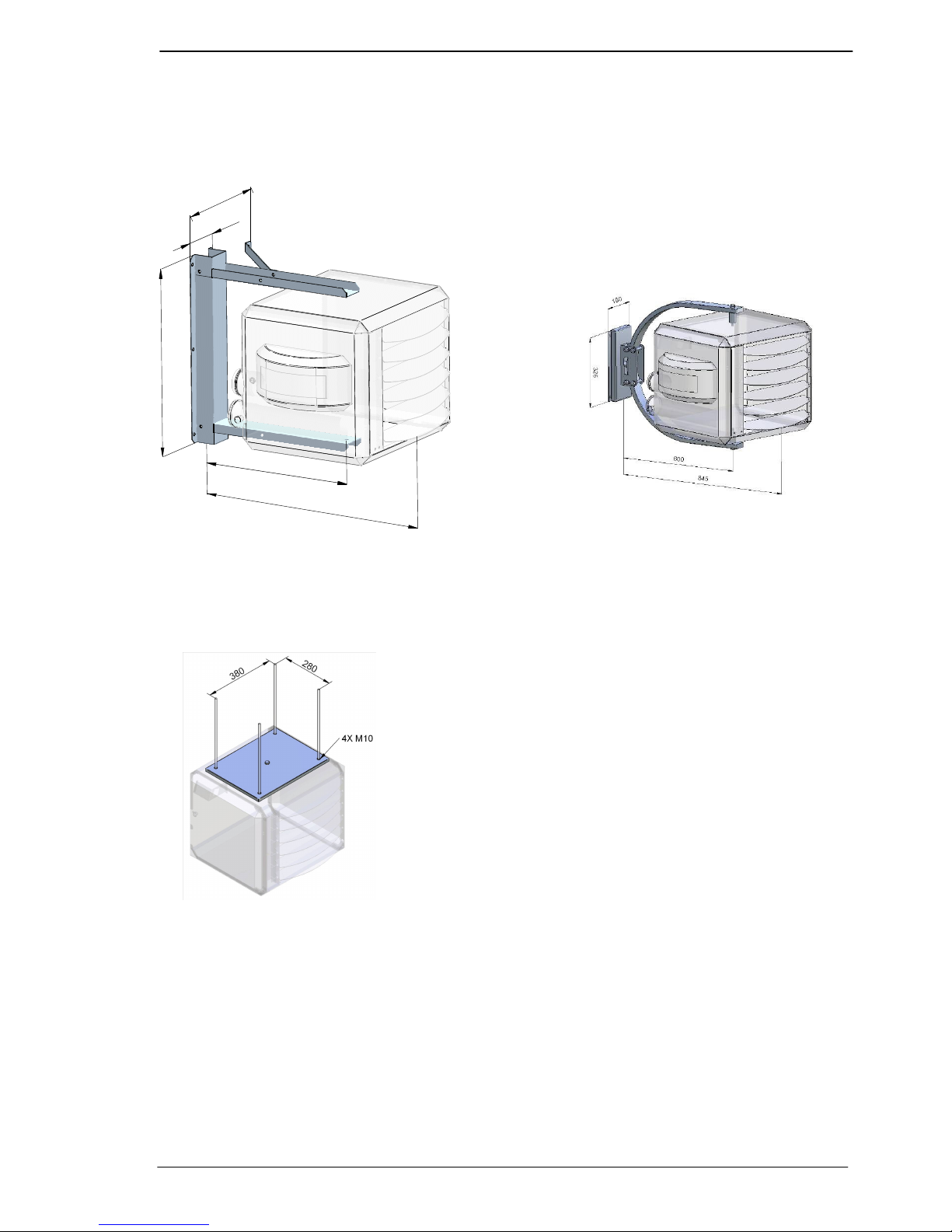
B
1
5
0
3
9
0
A
C
XR10-30 XR40-60
HR10-20 HR30-40
A 550 665
B 640 815
C 800 990
Available suspensions:
Standard bracket for type HR10 to 40 Design bracket type HR10 and 20
Horizontal horizontal
Suspension adapter for type HR10 and 20
M10 threaded bar
Instructions condensing Air heaters type HR
Page 9/31
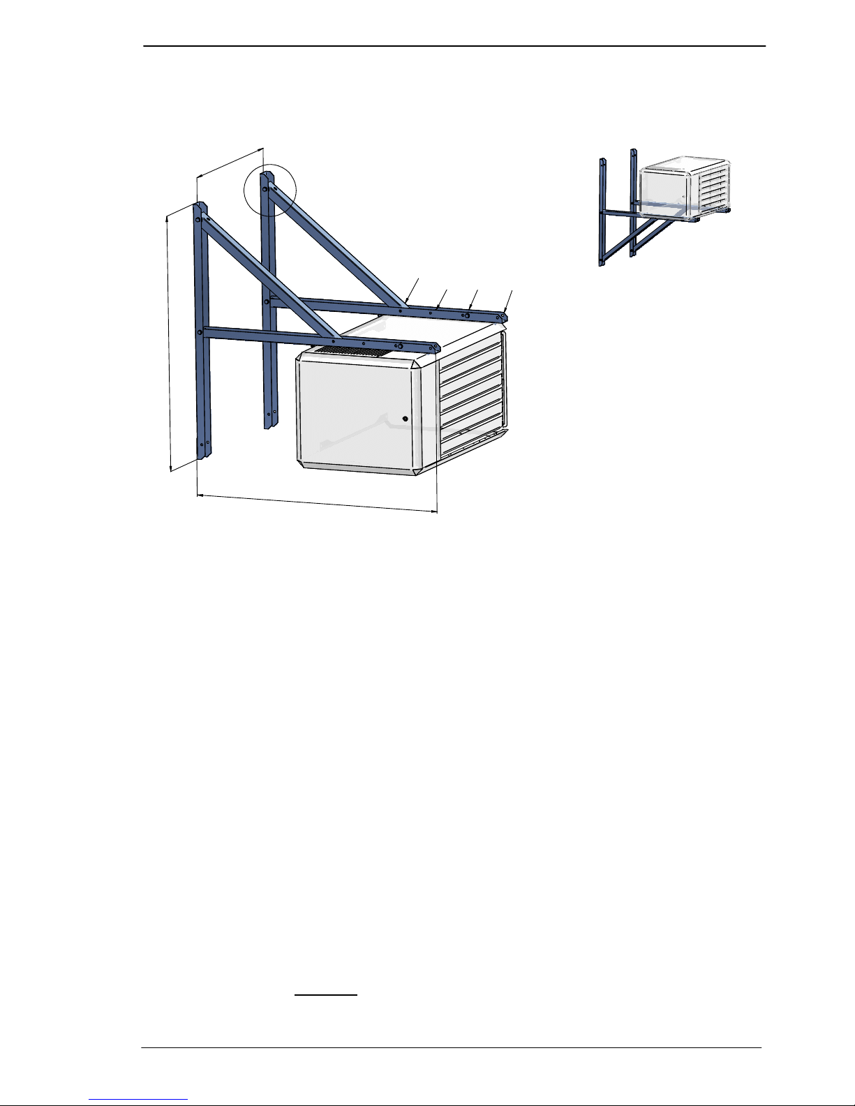
Wall console set HR30 up to 120
Art. Nr. : GA8580
1
2
0
0
1
2
0
0
S
e
e
i
n
s
t
a
l
l
a
t
i
o
n
m
a
n
u
a
l
45°
15° & 30°
Horizontal
15°
30°
45°
Horizontal
6.2 Gas connection
The gas supply line has to meet the national valid requirements and possibly the local
requirements of the building inspector, police or fire brigade. (In GB it must comply with Gas
Engineers publication UP-1 and UP-2 together with BS 6891.
A manual isolation valve in the supply line must be placed within reach of the heater, and all gas
lines must be mounted without any mechanical tension.
When testing the supply lines with pressures above 60 mbar, this manual valve at the heater
must be closed.
The working and standing supply pressure must be a minimum of 17 mbar, and a maximum of
30 mbar ,measured at the inlet pressure nipple of the gas control in the heater .
6.3 Electrical connection
6.3.1 230Vac supply
The installation must comply with local and national requirements, ( as well as IEE regulations)
The unit heater is delivered completely wired internally, where controls of any type are to be
added (e.g. room thermostat) , the relevant wiring diagrams must be followed to. Never use a
room thermostat to interrupt the electrical supply to the heater!
Make provisions to completely isolate the heater for maintenance purposes. This can be an
isolation switch (min.3mm contact opening gap) , a power plug or a non-switched fuse spur.
The wiring diagram for the heater can be found towards the end this manual.
The supply is 230Vac. with earth
. The control circuit is a two wire low voltage Argus-link bus
communication.
HR30 - 60
HR30 - 60
HR30 - 120 HR30 - 120
Instructions condensing Air heaters type HR
Page 10/31
6.3.2 Room thermostat
The heater can only be controlled by special modulating Winterwarm room thermostats:
The Multi Therm Comfort; modulating digital clock thermostat with optimiser. It can control 1 to
8 air heaters HR10 up to HR60 or 1 to 4 air heaters HR80 up to 120.
The Multi Therm Standard; modulating digital thermostat. It can control 1 to 8 air heaters
HR10 up to HR60 or 1 to 4 air heaters HR80 up to 120.
The Interface printboard; special designed interface module for connecting the air heaters with
Building Mangagement Systems. (0-10V (modulating input) signal, high/low signal,
external reset and other different in and outputs.
ON/OFF thermostat
The heater can not be controlled with a simple on/off thermostat.
In all cases the communication between heater and thermostat is based on a two wire, lowvoltage connection. In the appliance the wire for the thermostat has to be connected to
connection 4 and 5 (see also electrical wiring diagram) Attention: This also needs a change in
the settings on the print board, see chapter 11
When mounting the thermostat, take attention to the following items:
• Mount the thermostat in a place where the air can circulate free pass the thermostat. Take
notice that the sun does not shine directly upon the thermostat (in the winter). Do not
place the thermostat on a cold wall. Place the thermostat on an inner wall free from
draught.
Never place the thermostat within the throw of the heater.
6.3.3 Thermostat cable
In all cases the communication between the heater and the thermostat is based on a two wire,
low-voltage connection. In the appliance the wire for the thermostat has to be connected to
connection 4 and 5 (see also electrical wiring diagram).
Cable specification: signal cable, 1x2x0,8 (shielded and twisted)
Maximum length 250m.
If the cable is chosen too thin, the signal will become too poor. If the cable is not shielded and
twisted the signal might become disturbed in an EMC unfriendly environment.
Keep the thermostat cable separated from mains cables. Connect the earth shield of the cable
only to the earth terminal in the heater.
If these guidelines are not followed it may result in malfunction of the installation or worse, it
could damage the thermostat or the electronics in the heater.
Never mount the thermostat near aerials of internal communication networks.
These emit radiation that could lead to disturbance of the thermostat. Always keep
some meters distance.
6.3.4 Fuses
On the heater control HC there are two fuses. See electrical wiring diagram.
F1 and F2 are in the power supply of the heater. Replace the fuse only by a fuse of the same
type, 5AT
 Loading...