

Page 1
Instruction manual
DXA heater
pag
e 1
Inst
ruction manual
DXA Heater
Ver GB 50
3a
YOU MUST READ THIS DOCUMENT BEFORE COMMENCING INSTALLATION.
INSTRUCT THE USER ONCE TAKEN INTO USE AND KEEP THIS DOCUMENT
NEAR THE APPLIANCE
Date: 01
-09-
2009
Version: GB 50
3a
Appliances for GB
Natural gas, Propane, Butane, LPG
Page 2

Instruction manual
DXA heater
pag
e 2
Foreword
This installation and user
manual
is intended mainly for the gas, oil and electrical fitter. It also
provides instructions for the user and for the
maintenance of the air heater. To use this air
heater in a safe and effective way, it is strictly essential that this manual is used correctly.
Contents:
Pag
e
1
ABOUT THIS MANUAL
3
1.1
G
UARANTY
3
2
SAFETY INSTRUCTIONS AND PRECAUTIONS
3
2.1
K
EY TO SY
MBOLS
3
2.2
S
YMBOLS ON THE APPLIANCE
3
2.3
W
ARNINGS
3
2.4
PRE-
CHECK
. 4
2.5
S
AFETY PRECAUTIONS
4
2.6
W
ATER AND CHEMICAL SU
BSTANCES
5
2.7
U
SE IN A GREENHOUSE
5
2.8
U
SE IN A POULTRY SHED
5
3 INTRODUCTION DXA HEA
TER
5
4
INSTALLATION
6
4.1
M
OUNTING THE HEATER
6
4.2
G
AS CONNECTION
6
4.3
E
LECTRICITY SUPPLY
7
4.4
I
NTERFACE UNIT
; 8
4.5
C
HECKS BEFORE TAKEN I
NTO OPERATION
8
5
FUNCTION OF THE HEATER 9
5.1
F
UNCTION BUTTON ON TH
E HEATER
9
5.2
H
EAT DEMAND
9
5.3
DELAYED START 9
5.4
V
ENTILATION
10
5.5
T
EMPERATURE LIMITER
10
5.6
A
IR TRANSPORT,
VANE SWITCH
10
5.7
M
INIMUM GAS PRESSURE
SWITCH 10
5.8
D
ESCRIPTION HEATER CO
NTROL
HC
10
5.9
G
AS CIRCUIT
11
5.10
M
EASURING AND ADJUSTI
NG THE BURNER PRESSURE 11
5.11
M
EASURING COMBUSTION
VALUES
12
6
MAINTAINING THE HEATER 12
6.1
G
ENERAL MA
INTENANCE
13
6.2
E
XTENSIVE MAINTENANCE
IN A POULTRY SHED
13
6.3
C
LEANING THE BURNER U
NIT
13
6.4
C
HANGING GAS TYPE
14
6.5
S
PARE PARTS
14
7
PROBLEM SOLVING
15
7.1
G
ENERAL
15
7.2
E
RROR CODES
15
8
WIRING DIAGRAM
17
9
SPECIFICATIONS
19
9.1 DXA H
EATER
75
19
9.2 DXA H
EATER
100
20
9.3 DXA H
EATER
120
21
Page 3
Instruction manual
DXA heater
pag
e 3
1
About this manual
In this manual you will find information on the DX Heater. One section of this is intended to
enable the user of the DX Heater to operate the appliance in a sensib
le and safe way. Another
section is intended to enable the fitter or service technician to fit, set up and maintain the DX
Heater, and to detect and resolve any malfunctions quickly and effectively.
This manual makes regular mention of a fitter or serv
ice technician. This refers to a qualified
fitter or service technician who is trained in the fitting, malfunction-free operation and
maintenance of the DX Heater. He is also competent to carry out work on a heater.
1.1
Gu
arant
y
Guaranty is only valid when the
appliances are used
and or installed according to thi
s manual.
2 Safety instructions and precautions
Always read the entire manual so that you are familiar with all the safety instructions and
precautions.
2.1 Key to symbols
Safety warning: warning of danger
of physical injury or (direct) damage to product, animals or
the environment.
Warning
Information
Tip
2.2 Symbols on the appliance
Warning which refers to the manual for information on the component on or next to which the
warning is positioned
.
Warni
ng of the potential hazard of electric shock.
Safety grounding
2.3
Wa
rnings
Keep this manual in a safe place near the heater so that you can consult the manual whenever
necessary
Incorrect use of the heater can result in physical injury. Therefore, follow
the instruction below
carefully:
•
Avoid physical contact with the motor or other hot parts of the heater.
•
Do not touch live parts of the heater.
•
Keep body parts, loose items of clothing, jewellery or hair away from rotating fan blades or
other movin
g parts of the heater.
•
Do not pl
ace articles in front or nearby
the heater because this can cause fire hazard.
The following conditions can lead to damage to the heater:
• •
Incorrect transportation or storage of the heater;
• •
Errors in the assembly of (
parts of) the heater;
• •
Excessively high or low oil pressure;
• •
Excessively high or low ambient temperature;
• •
Wear, ageing and metal fatigue in components of the heater.
• •
Moisture: the heater has IPX4D protection grade
.
Page 4
Instruction manual
DXA heater
pag
e 4
2.4 Pre-check.
Before unpacking and i
nstallation, please check (i.e. on the data badges) if the heater
corresponds to the order and if it is suitable for the local present provisions (gas type, gas
pressure, electrical supply etc.)
The installation must comply with all applicable local and n
ational standards.
The installation of the air heater must be in accordance with the relevant requirements of the
Gas Safety Regulations (for example in GB; The Institute of Gas Engineers IGE UP-1 and 2),
Building Regulations and the IIE Regulations also incorporating the gas safety (installation and
use) regulations. Other national and/or local regulations may apply (the Local Authority, Fire
Officer and Insurers)
The competent installer must make sure the heater operates correctly and must instruct the
user about the safe operation of the heater.
This heater is takes its combustion air from within the room in which it is located, the necessary
ventilation requirements must be followed for gas safety regulations.
The heater should not be installed in are
as containing corrosive or explosive vapours
. P
lease
consult your supplier;
otherwise the guarantee will become invalidated.
Make sure that the warm air can be blown out freely. There should absolutely be no (possibility
of) materials within 5m from the f
ront of the heater.
The heater has been tested in detail on safety and correct operating settings before leaving the
factory. It has been adjusted for the type of gas that is stated on the data badge. Should there
be any doubt, please contact your suppli
er.
2.5 Safety precautions
If the distance between hot flue gas coming from the outlet cover and people or animals is too
short, this may pose a danger to them. In addition, the heater is started automatically, which
may pose a risk to people or animals in the
vicinity of the heater. Therefore, you should always
observe the prescribed minimum distances between the heater and people, animals and crops
(refer to Mounting the heater)
O2 is
used during gas combustion and converted, amongst others, to CO2. Too much CO2 in
the air may be harmful to people, animals and crops. Therefore, you should always ensure
sufficient fresh air can enter the space where the heater has been placed, e.g. by way of open
windows or a separate fresh air intake.
When the CO2 concentrat
ion is too high, the heater will
not function properly. There may be incomplete combustion. (Danger of Carbon Monoxide CO)
The CO2 concentration may not exceed 1%. Minimal ventilation requirements 1000m3/h for
each 100kW installed power.
Observe the follo
wing precautions when using the heater:
•
Only start the heater if access panels and protective grill have been fitted.
•
Have the heater checked and serviced once a year by a service technician.
•
This appliance is not intended for use by persons (including
children) with reduced
physical, sensory or mental capabilities, or lack of experience and knowledge, unless
they have been given supervision or instruction concerning use of the appliance by a
person responsible for their safety.
•
Children should be superv
ised to ensure that they do not play with the appliance.
•
Children may only be present in the space where the heater has been placed if
supervised by an adult.
•
Ensure the socket outlet is located within a 2 m radius of the heater and that the plug can
be r
emoved easily and quickly from the socket outlet.
•
Leave the plug in the socket outlet even if you are not using the heater. This prevents
condensation of the print circuit board; this may lead to heater damage and/or
malfunctions.
•
Make sure the mains cabl
e does not get damaged. Replace a damaged cable
immediately.
Page 5
Instruction manual
DXA heater
pag
e 5
•
Do not connect the heater to an air duct, as this has a negative effect on the performance
of the heater.
•
Due to the presence of CO2 and the noise levels produced, you must obtain permission
f
rom the safety and health service before taking a heater into use that is to be placed
•
Minimal ventilation requirements 1000m3/h for each 100kW installed power.
•
In case of a malfunction, ensure the heater is free of electricity by removing the plug from
t
he socket outlet, in order to prevent damage to the heater.
2.6 Water and chemical substances
Observe the following measures if water or chemical substances that could be dangerous to
people, animals, and/or crops are used in the space where the heater has
been placed:
•
Switch off the heater.
•
Make sure the heater cannot be started automatically by removing the plug from the
socket outlet.
•
Close the gas tap.
•
Cover the heater.
2.7 Use in a greenhouse
Observe the following additional measures when using the h
eater in a greenhouse:
•
The CO2 level should not exceed 1% (10,000 ppm).
•
In completely enclosed greenhouses there must be at least 100 m3 fresh air per m3 of
gas and external atmospheric protection.
Or Minimal ventilation requirements 1000m3/h
for each
100kW installed power.
•
There must be at least two openings in the space to ensure adequate circulation of air if
no artificial ventilation is present.
•
Use the heater preferably in combination with one or more exhaust fans and a
CO2 meter
•
Do not use any su
lphurous fuels in the space where the heater has been placed, as these
contain high amounts of sulphur that could be harmful.
2.8 Use in a poultry shed
When cleaning and disinfecting a poultry shed in which a heater has been placed, or when
spreading sawdus
t, the following precautions should be taken. Failure to take these precautions
will give rise to a risk of explosion or fire.
Take the following into account when using the heater in a poultry shed:
•
The CO2
content must not exceed 0.3% (3,000 ppm).
•
If
no artificial ventilation is provided, there must be at least two openings in the space to
ensure sufficient circulation of air.
•
Cover or remove the heater when cleaning or disinfecting the poultry shed.
•
When spreading sawdust the heater must be covered
to prevent sawdust particles from
entering the heater and creating a fire hazard. Also make sure that the heater cannot be
started automatically by removing the plug from the socket outlet. Also close the gas
valve.
•
Clean the heater after every poultry s
hed clean-out to prevent the heater from becoming
dirty.
•
Do not use water when cleaning the heater
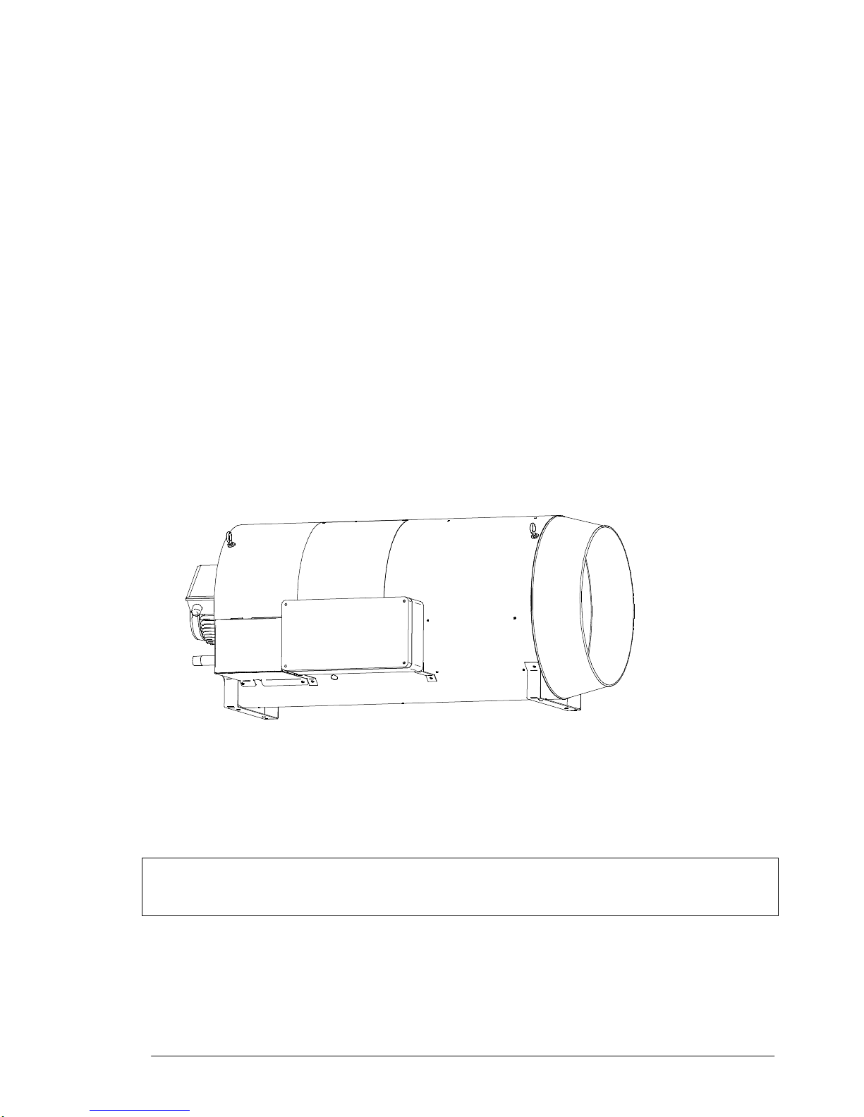
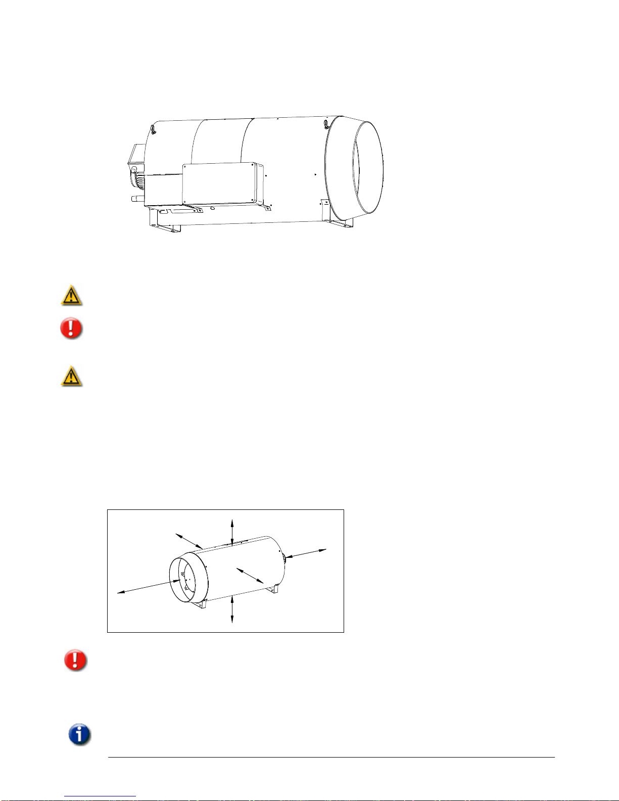
3
Introducti
on
DXA heater
The DX Heater is a direct fired heater designed specifically for greenhouses and poultry sheds.
The device is placed in the enclosed
space itself, which means that the heater displaces air only
and uses a small amount of energy to warm and ventilate the space. The large air capacity and
the unique shape of the heater also ensure that the device can distribute the air within the
space i
n the best possible manner.
The heater's design is aimed at straightforward installation, maintenance and safe use.
Ignition and combustion for example are controlled automatically and parts are easily accessible
for cleaning and maintenance.
Page 6
Instruction manual
DXA heater
pag
e 6
The heater
can be ordered for different gas types and fuel settings:
•
Natural gas
•
Propane
, Butane and LPG
•
Paraffin and Diesel
4
Installati
on
Read the chapter on Safety instructions and precautions first and observe all warnings and
precautions. Follow all instructio
ns in this chapter explicitly.
Only skilled installers or service technicians are permitted to install the heater.
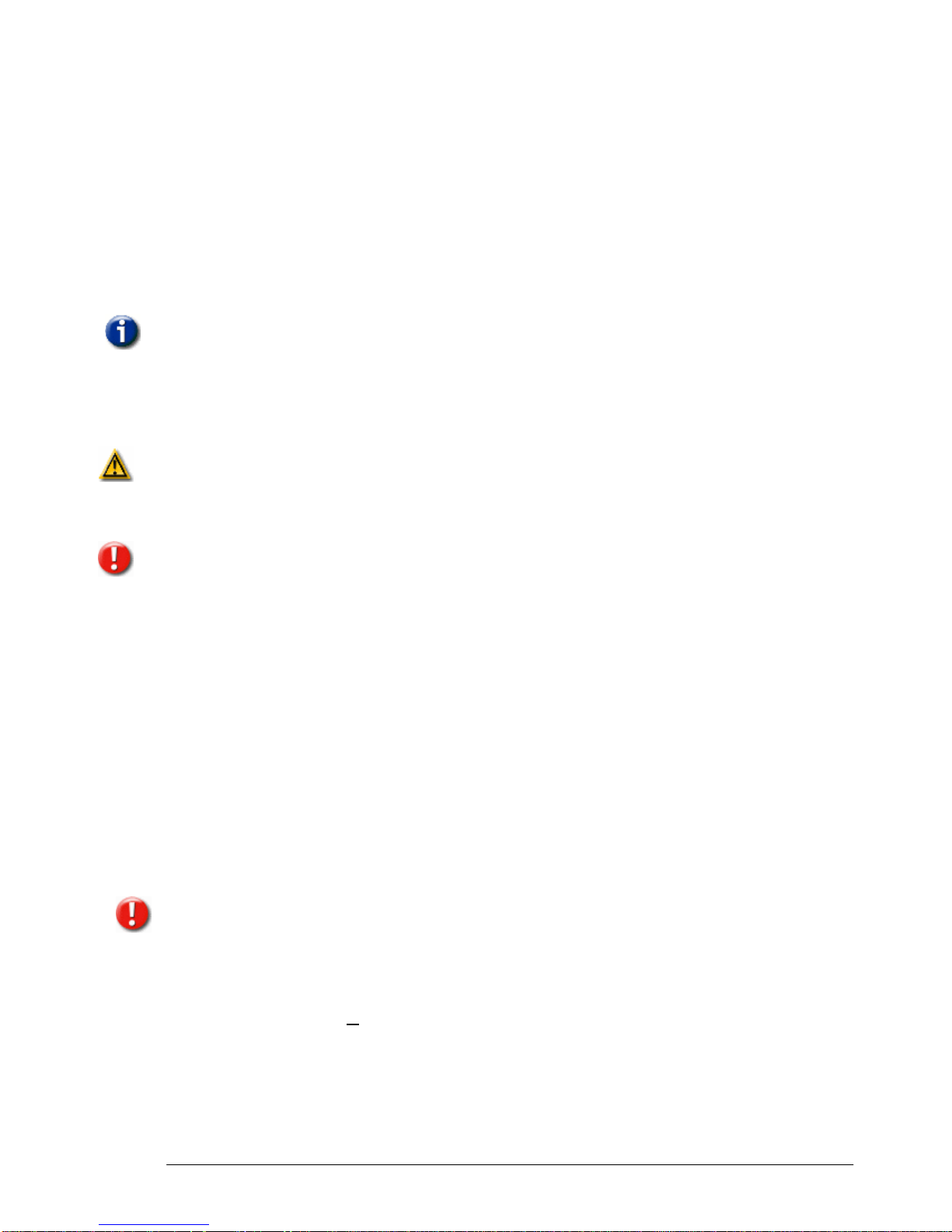
4.1 Mounting the heater
Mount the heater in a sturdy manner, taking into account the dynamic load and the weight of the
appliance (refer to
Specifications ).
Take the following into account when installing the heater:
•
Attach chains to the four hook eyes and suspend the heater.
•
Make sure the heater is positioned horizontally otherwise it will not operate (properly).
•
Do not connect the heat
er to an air duct, as this has a negative effect on its performance.
•
Take into account the minimal distances between the heater and people, animals and
crops:
• 5
m on the outlet side;
•
3 m on the inlet side;
•
1 m on the other sides.
5
m
1m
1
m
1m
1
m
3
m
The same minim
um distances apply between the heater and walls, glass and other objects, with
the exception of the outlet side. The minimum distance on this side must be equal to the throw
that the heater is capable of producing. This depends on the type of heater (refer
to
Specifications ).
4.2 Gas connection
To connect the heater to the gas network, your supplier
can
supply a gas connection set that
consists of a ball plug valve, (reducing) nipples, gas filter, gas pressure regulator and gas hose.
A set is available for ev
ery type of gas.
Page 7
Instruction manual
DXA heater
pag
e 7
Keep the following in mind when connecting the heater to the gas network
.
The gas supply line has to meet the national valid requirements and possibly the local
requirements of the building inspector, police or fire brigade. (
For example in GB it must comply
with Gas Engineers publication UP-1 and UP-2 together with BS 6891.)
A manual isolation valve in the supply line must be placed within reach of the heater, and all gas
lines must be mounted without any mechanical tension.
When testin
g the supply lines with pressures above 60 mbar, this manual valve at the heater
must be closed.
The working and standing supply pressure must be between 17mbar and 50mbar, measured at
the inlet pressure nipple of the gas control in the heater.
The burner
pressure is pre-adjusted (see technical details). The burner pressure can be
measured on the P-out measure point on the gas valve.
There is a kit available for changing the
gas type
. (from natural gas to propane / butane or vice
versa) The gas
nozzle
ha
s to be exchanged and the
burner pressure
readjusted. Look into the
specifications for the exact adjustments. Instructions can be found in this manual.
4.3 Electricity supply
4.3.1 230Vac
supply
The installation must comply with local and national requirements, (as well as IEE regulations).
The unit heater is delivered completely internally wired. Where controls of any type are to be
added (e.g. room thermostat), the relevant wiring diagrams must be followed. Never use a room
thermostat to interrupt the electrical s
upply to the heater!
The supply is 230Vac 50Hz with earth. When the
supply
voltage is lower than 195V and higher
than 255V the correct functioning of the heater is not
guarantied.
A mains cable including plug is supplied with the heater. The wires
of t
he cable
must
be connected to the
clamps in the connection box. Make sure you do not damage the mains
cable. Replace a damaged cable immediately.
When the heater is connected without a plug, m
ake provisions to completely isolate the heater
for maintenance
purposes. This can be an isolation switch (min. 3mm contact opening gap).
The switch should not interrupt earth.
Ensure the plug or switch is located within a 2 m radius of the heater and the plug can be
removed easily and quickly from the socket
4.3.2 Thermost
at connection
The heater can be controlled in various ways. It can be controlled by a simple ON / OFF signal,
but it can also be controlled by an external print.
4.3.3 Thermostat cable
In all cases the communication between the heater and the thermostat is base
d on a two wire,
low-voltage connection. (see also electrical wiring diagram).
Cable specification: signal cable, 1x2x0,8 (shielded and twisted)
Maximum length 200m.
If the chosen cable is too thin, the signal will be too weak and heater will not work
. I
f the cable is
not shielded and twisted the signal might become disturbed in an EMC unfriendly environment.
Keep the thermostat cable separated from mains cables. Connect the earth shield of the cable
only to the earth terminal in the heater.
If these gui
delines are not followed it may result in malfunction of the installation or worse, it
could damage the thermostat or the electronics in the heater.
4.3.4 Simple ON / OFF contact
(standard configuration)
The heater can be connected to a potential free ON/OFF co
ntact.
Page 8

Instruction manual
DXA heater
pag
e 8
1 2 3 4 5 6 7 8
ON
1 2 3 4 5 6 7 8
ON
1 2 3 4 5 6 7 8
ON
0
1
S2
S3
0
1
0
1
PE
N65
L
Neutal
L (230V AC)
Heater 1
Neutal
L (230V AC)
Heater 2
Neutal
L (230V AC)
Heater 3
Neutal
L (230V AC)
Heater 8
Max. 8 Hea
ter
s
Communication bus:
2 wires; low voltage
T
On Of
f thermostat
PE
N65
L
PE
N65
L
PE
N65
L
Neutal
L (230V AC)
Heater 1
Neutal
L (230V AC)
Heater 2
Neutal
L (230V AC)
Heater 3
22°C
The heater will only react on the heat demand. Remote reset or the ventilation signal can only
be made on the heater itself.
The following (Standard) settings on the main board in the heater
have to be actual.
•
The
S2
micro switches on the main boa
rd have to be set to
OFF, see example.
•
The switch S3 has to be set to 1.
•
The thermostat has to be connected to the clamps 5 and 6 in the heater.
•
In the case that more than 1 heater is connected to 1 thermostat, do not exchange clamp
5 with clamp 6 between
the heaters. This will result in permanent burning of the heaters.
Any changes too these switches must be performed with the power off, otherwise any changes
made will not take effect.
4.4 Interface Unit;
Special designed module to connect t
he heaters to external
climate computers. This unit has connections for Burner ON /
OFF, Ventilation
, Reset function in case of faults and some
outputs are available (faults for example) The unit can control
up to 8 heaters.
When this unit is used the set
tings in the heater have to change.
Each heater needs its own unique number to recognise the heater
by the room thermostat. The number of the heater can be set by
the micro switch S2 on the heater control in the heater. The
number at the upper position of
the switch is the given number for
that heater. Make sure that each heater has is own unique number.
If more than one heater has the same number the system does not
work.
Any changes too these switches must be performed with the power
off, otherwise any ch
anges made will not take effect.
The switch S3 has to be set to 0 (off)
It is possible you may have the incorrect settings with the system still working! However if this is
the case, you will ultimately damage the equipment. So every care should be take
n to ensure
the switches are set correctly!
4.5
C
hecks before taken into operation
Perform the following checks before taking the heater into
operation
.
•
Wiring
, Ensure the heater is free of electricity by removing the plug from the socket outlet.
Now check th
at the connection is OK and that the wiring is connected properly
.
•
Gas
soundness, Open the gas valve and check if the heater is gas-tight, using a leak
detector spray for example
.
1 2 3 4 5 6 7 8
ON
10
S3
S2
Page 9

Instruction manual
DXA heater
pag
e 9
•
Supply
voltage; check
if the supply voltage is sufficient.
•
Transport and com
bustion air flow, Check if the transport and combustion air exhaust is
free from any obstacles. In this way, you will prevent the heater from continuing to
operate while the air exhaust is blocked
.
•
Burner pressure
, The heater will not operate if the burner
pressure is too high or too low;
refer to Measuring the burner pressure
•
Flame detection
, Flame
detection is by means of ionisation. The ionisation probe is placed
inside the flame. When the flame does not
touch
the pen or the probe is polluted the
heater
will
not function.
•
CO-value and
CO2-readings in the combustion air
too
high a level of CO and/or CO2 in
an enclosed space can be harmful to people, animals and crops. You should therefore
always verify that the CO value and the CO2 content in the flue gas
comply with the
requirements; refer to Measuring combustion values
•
General heater operation
.
5 Function of the heater
5.1
Functi
on button on the heater
O
n the control panel on the heater there is a function button. T
his button has several functions:
When the b
utton is pushed once (1X) the heater will start to burn. When the button is pushed
again the heater will stop. The heater will remain in the burn mode for maximal 24 hour. Every
hour the heater will perform a safety shutdown and will automatically restart.
When the button is pushed twice (2X shortly) the heater will start to ventilate (without burning).
The heater will stop to ventilate when the button is pushed again.
When the heater is in error, it can be reset by pushing this button once.
5.2 Heat demand
The heat demand can be generated by means of the room thermostat or
manually
by pushing
the function button on the heater.
If the
re is
heat demand, the following cycle will start:
1. Internal checks: The heater performs several checks before there happens
anything.
2. Gas pressure
check. The heater will check if the minimum gas pressure switch is closed.
If not the heater wil generate an E7 error. This error resets itself when the gas pressure
is back.
3. Pre purge
: The electronic circuit board acknowledges the h
eat-demand and the
fan
will
start running for 15 seconds. (Display print
1)
4. Ignition
: After 15 seconds of pre purge, the electrode will spark for max. 5 seconds, the
gas
valve is opened and the
gas air
mixture will ignite. (Display print
2)
5. Burn
: When
the flame is detected (Display print b) the unit will go into burn mode.
6. End of heat demand:
When the heat demand ends, the burner will switch off and the
system fan will continue to run for ca. 1
minute
in order to cool the unit down (Display
print
P)
.
The unit will try to ignite
5 times
before lockout on flame fault.
In the case of flame failure during operation, the heater will attempt one restart.
When the heater is in lockout you see in the display intermittent A1. On the display of the room
thermo
stat you see failure 1.
Every hour the heater performs a safety shut down. After this shutdown the heater wil restart
automatically.
5.3 Delayed start
Often more than one heater are
connected to one control unit. When all the units are starting on
at the s
ame time, a pressure drop in the gas supply can occur. This may result in some heaters
Page 10

Instruction manual
DXA heater
page 10
not starting. To prevent this there is a random waiting time before the heater starts. In this
manner the pressure drop in the gas supply stays to a minimum.
5.4 Ventilati
on
By means of the optional external interface board, the fan in the heater can start
without the
burning from the heater. The
symbol
F
will
be displayed on the heater.
The fan can also be operated manually by pushing the function button twice.
This manu
al ventilation setting will remain maximum 24 hour.
5.5 Temperatu
re limiter
The temperature from the combustion chamber is mea
sured by a NTC sensor. When the
temperature
from this sensor becomes too high the heater will stop burning. (Display E / 1) The
hea
ter will start if the sensor is cooled again.
When the temperature becomes much too hot the heater will stop, and will be locked. The
heater will only start after a manual reset. (Display A / 2).
5.6 Air transport, vane switch
In
the air stream inside the hea
ter a vane
switch
is mounted. When the fan is running this switch
should
be made. If not, Error E8. The heater will perform a retry for 5 times. When
the vane
switch is still not closed the heater will lock with error A8 and has to be reset
manually
.
When
during one heat demand the
vane
switch opens more than 5 times the heater will also
stop. Error A8.
When the heater is in standby and the
vane
switch is closed, the heater will
give
error E8
until
the switch is open again.
5.7 Minimum gas
pressure switch
The
gas supply pressure during standby and operation should be between certain values.
For natural gas it should be between 17 and 30 mbar and for propane it should be between 25
and 57 mbar.
When the supply pressure is too low, the heater will not operate an
d will generate an error E7.
The setting from the pressure switch is shown in the specifications.
Attention, this is a safety issue. When the pressure becomes too low the safe combustion
becomes an issue. The combustion gasses may become
harmful
for man,
animals and crop.
It is normal that during the start of the heater the pressure drops a bit. The heater will not react
on this
. Only when before and during burning the pressure is stays to low for a longer period the
heater will stop, and automatically r
estart when the pressure is available again.
5.8 Description heater control HC
The heater control HC controls the unit and communicates with the room thermostat.
Functions integrated in the heater control HC are:
-
Two
wire communication with room thermostat
-
ionisation flame guard on burner
-
controlling the gas valve
-
guarding the temperature of the heat exchanger
-
LED signals status of heater, heat demand: green, failure: red
-
Status of heater on 8 segment display on heater control HC
-
reset of heater
-
servic
e mode function
Page 11

Instruction manual
DXA heater
page 11
1
2
3
6 7
8
9
10
5
4
4
Lay-out print board
J2
Fuse 5AT
J4
J8
U11
S1 J12
J6
S2
S3
J9
T2
J15
J7
0
1
123 4
5 6 7 8
on
Argus vision
J2
Main power connection 230V
J4
Connection for gas valve and
the N for
system fan relay
J6
Connection for room thermostat, appliance recognition
J7
Earth burner
J8 Fase for
system fan
rellay
and ignition transformer
J9
Not used
J12
Connections for Temperature sensors, vane switch and gas pressure switch
J15
Ionisation
F1
&
F2
Fuses 2x 5AT
U11
Status display
S1
Reset service button
S2
Micro switch heater no. Standard all on OFF
S3
Power supply thermostat standard
S3 op 1
T2
not used
5.9 Gas circuit
The
gas circuit
from the DXA has the following parts:
1. Gas connection
¾”
pipe thread
2. Minimum gas
pressure switch
3. Gas
valve
4. Nut with
mechanical union
22mm
5. Gas
pipe
22mm
6. Nozzle
7. Flame stabilizer
8. Ignition electrode
9. Connection
boot
2x
10. Ignition cable
2x
5.10 Measuring and adjusting the burner pressure
Right on the measuring
point (
1) the
minimum gas pressure switch is mounted.
(1)
Measuring
point gas supply pressure
(2)
Measuring
point burner pressure
(3)
Adjusting
the burner pressure
1. Switch off the heater.
2. Unscrew and remove the screw of the measuring nipple (2).
3. Connect a pressure gauge to the measuring nipple.
Page 12

Instruction manual
DXA heater
page 12
4. Switch on the heater and start heating manually by pressing the button on the operating
panel.
5. Check whether the b
urner pressure is equal to the nominal burner pressure for the
corresponding heater type (refer to
Specifications).
6. Record the measured value as a reference for the next measurement.
7. If the burner pressure does not correspond with the specified value:
a.
T
urn the adjusting screw (3) either to the right or the left until the specified value
is indicated on the gauge.
b. Check the burner pressure again following the steps outlined above.
8. Switch off the heater and allow the heater to cool.
9. Remove the pressure g
auge and retighten the screw of the measuring nipple (2).
5.11
Measuring combustion values
Probe
Heater with probe
CO2 percentage (approximate
)
Nominal
CO2 percentage (airtime 20°C)
Gas type
DXA 75
DXA 100
DXA 120
H
igh
calori
fic gas
(G20)
7,5%
7,5%
7,5%
Low
calori
fic gas
(G25)
7,7%
7,7%
7,7%
Butane (G30)
8,5%
8,5%
8,5%
Propane (G31)
8,5%
8,5%
8,5%
LPG
8,
0%
8,
0%
8,
0%
1. Switch off the heater.
2. Place the probe (1) on the heater (refer to figure
DX Heater with probe
) and connect the
(calibrated) flue gas anal
ysis equipment.
3. Switch on the heater and start heating manually by pressing the button on the operating
panel.
4. Allow the heater to heat for about 5 minutes.
5. Measure the CO value.
6. Measure the
CO2 percentage
in the flue gas.
7. Record the CO value reading
and the
CO2 percentage
as a reference for the next
measurement.
8. If the CO value exceeds 15 ppm, or if the CO2 percentage does not correspond to the
specified percentage, refer to theCO2 percentages (average ambient temperature 20°C)
a. Check CO2 percentage
if
deviates by more than 1 %,
check the burner pressure
air inlet openings of the system fan
.
b. Measure the burner pressure; refer t
o Measuring the burner pressure.
c. Check whether the gas pipe diameter
(gas pressure to low).
d. Check the CO value and the CO2
percentage again following the steps outlined
above.
9. Switch off the heater.
Allow the heater to cool down and then remove the probe and the flue gas analysis equipment
6
Maintaining the heater
It is recommended to have the heater checked and serviced by
a service technician every
year to guarantee reliable and safe operation. Heaters used in poultry sheds must be serviced
more often and more extensively due to high levels of dust and dirt in these types of spaces.
Page 13

Instruction manual
DXA heater
page 13
6 7
8
9
10
4
6.1 General maintenance
The heater must
be free of electricity during servicing. Remove the plug from the socket outlet.
Do not use water when cleaning the unit.
Perform the following activities during general maintenance:
•
Open the body access panel and especially clean the body, fan blades, f
an motors, vane
swi
tch, maximum thermostat
and swirl ring.
•
Grease any parts and bolts that are loosened regularly for maintenance.
•
Check whether the wiring, nuts and bolts are all properly tightened.
•
Open the gas valve and check whether the heater and t
he gas hose are gas-tight.
6.2 Extensive maintenance in a poultry shed
The heater must be free of electricity during servicing. Remove the plug from the socket outlet.
Do not use water when cleaning the heater.
Clean and check heaters used in poultry sh
eds after every shed clean-out and before spreading
sawdust. To do this, carry out the following actions:
1. Use compressed air to blow the parts clean, especially the inside and outside of the body,
fan blades, fan motor, vane switch and the maximum thermos
tat.
2. Remove all dust from the motor as the layer of dust acts as insulation, which can cause
the motor to overheat.
3. Use a brush to remove any caked on dust.
4. Clean the burner unit (refer to Cleaning the burner unit).
5. Put the Power back on and let the he
ater heat for a while so that if any dust particles have
remained behind, they are now burnt.
6. Stop heating and cover the heater once it has fully cooled off.
7. Make sure the heater is free of electricity by removing the plug from the socket outlet.
8. Disinf
ect the poultry shed and spread the sawdust.
9. Remove the cover from the heater.
To ensure the instructions below are carried out safely, it is recommended having these
carried out exclusively by a service technician.
Perform the following checks after
cleaning the heater:
•
Open the gas valve and check whether the gas hose is gas-tight.
•
If the heater has been moved, check whether the gas hoses are connected properly.
Connections that slip off or that are improperly mounted can create a fire hazard.
•
Ch
eck that the wiring is properly secured.
Finally, carry out all the checks that are performed during heater installation (refer to Performing
checks :
1.
Measure
the burner pressure;
2.
Measure
combustion values;
3
.
General
heater operation.
Place
and close the access panels once you have completed all checks. The heater may now
be used again.
6.3 Cleaning the burner unit
The burner unit can easily be removed out of the heater.
•
Open
the inspection hatch
•
Remove the gas pipe by unscrewing the 2 nuts
wit
h mechanical union 22mm.
•
Remove the 2 connecting boots from the ignition
electrode by pulling gently at the cables
.
•
Unscrew the 4 nuts where the burner unit connects
to the air inlet.
•
Take the burner unit out the heater
Page 14

Instruction manual
DXA heater
page 14
6 7
8
9
10
4
The burner unit has the following
parts:
4
Nut with mechanical union 22mm
5 Gas pipe 22mm
6 Nozzle
7 Flame stabilizer
8 Ignition electrode
9 Connection boot 2x
10 Ignition cable 2x
Clean the various parts with a soft brush ,a coth or compressed air.
Pay attention to dirt building up on
the stabilizer and the ignition pen.
The distance between the electrodes should be 3 mm.
6.4 Changing
gas type
The heater is suited for different types of gas, natural gas or propane / Butane
.
To change from natural gas to propane or butane (or vice versa) th
e nozzle (6) has to be
changed.
To ensure the instructions below are carried out safely, it is recommended having these carried
out exclusively by a service technician.
•
Open the inspection hatch
•
Remove the gas pipe by unscrewing the 2 nuts with mechani
cal union 22mm.
•
Remove the 2 connecting boots from the ignition electrode by pulling gently at the cables.
•
Unscrew the 4 nuts where the burner unit connects to the air inlet.
•
Take the burner unit out the heater
Disassemble the burner unit
:
•
Remove the sta
bilizer (7) from the Nozzle (6)
•
Remove the flange from the nozzle by unscrewing
the nut from the nozzle.
Take the new injector and assemble everything again.
Look at the table with the technical details in the back of
this manual for the proper diameters
from the nozzles
and the right burner pressure.
When
everything is assembled again, make the following
checks:
Perform the following checks after cleaning the heater:
•
Open the gas valve and check whether the gas hose is gas-tight.
•
If the heater has be
en moved, check whether the gas hoses are connected properly.
Connections that slip off or that are improperly mounted can create a fire hazard.
•
Check that the wiring is properly secured.
Finally, carry out all the checks that are performed during heater installation (refer to Performing
checks :
1.
Measure
the burner pressure;
2.
Measure
combustion values;
3
.
General
heater operation.
Place and close the access panels once you have completed all checks. The heater may now
be used again.
6.5 Spare Parts
Name
75
100
120
Page 15

Instruction manual
DXA heater
page 15
Gas
valve
Fan
motor
Fan blade
Ignition electrode
Ionisation
electrode
Ignition cable
Ignition
transformer
V
ane switch assembly
Stabilizer
Control unit
Minimum Gas
pressure switch
Fan relay
Tempe
rature sensor
Propane Kit
Natural gas Kit
7
Problem solving
7.1 General
When it turns out that the problem is
not
caused by the external circumstances (i.e. no electric
supply power or no gas), please take the following instructions into account. Please remembe
r
the built in waiting times of the heater (do not react too soon!) and the code on the display on
the electronic circuit board.
To simplify the investigation of the failing heater please check first:
•
the fuses as well as the wires and plugs in the heater
for possible loose contacts.
•
Use first the service-button to put the heater in run mode, try later the room thermostat.
7.2 Error codes
Volatile lock out : Can only be reset by hand
A/0
Blinking
Internal failure
Defective print board
A/1
Blinking
No flame
Wi
thin 5 sec flame, then flame failure: Cause 1
No flame: Cause 2
A/2
Blinking
Exchanger too hot
Heater stops because the temperature of the heat exchanger is
too high: Cause 3
A/3
Blinking
Sensor error
Temperature sensor on heat exchanger error: Cause 4
A/4
Blinking
Too many flame
failures
Too many flame failures on ionization: Cause 1, 5
A/5
Blinking
Internal error
Too many problems with power supply. Try other Fase if
possible. Control unit defective, change control unit.
A/6
Blinking
Internal error
Too many problems with power supply. Try other Fase if
possible. Control unit defective, change control unit.
A/7
Blinking
Flame
Flame detection when there should not be a flame
A/8
Blinking
V
ane switch / Fan
Fan does not run: Cause 6
Fan runs: Cause 7
Non volatile lockout:
will disappear when the error is cleared.
E/0
Blinking
Internal defect
Defective print board
Page 16

Instruction manual
DXA heater
page 16
E/1
Blinking
1st temperature
safety
Heater stops because the temperature of the heat exchanger is
too high. When the heater is cooled down, the heater will
restart: Cause 3
E/2
Blinking
Selection
resistance
Heater recognition does not work: Cause 8
E/3
Blinking
Selection
resistance
Heater recognition does not work: Cause 8
e/7
Blinking
Gas
pressure
switch
Gas supply pressure too low, che
ck gas supply pressure
.
e/8
Blinking
Fan / V
ane switch
Fan does not run: Cause 6
Fan runs: Cause 7
E/9
Blinking
Reset error
Too many switches on reset button: Cause 9
Cause 1:
Within 5 sec flame, then flames failure.
•
The flame is not detected. Check
the ignition cable and electrode. (cable resistance 1K
ohm
•
The heater has electrically a poor earth.
•
The print board is defective.
Cause 2:
•
There is not enough gas pressure.
•
The burner pressure is too low, adjust the gas valve
•
The gas valve does not open
, check during ignition on 230V on the valve.
•
Check whether the ignition electrode sparks, replace cable, electrode
Cause 3:
Heat exchanger too hot
•
Check if the system fan blows enough air.
•
Check the setting of the gas valve, the heater may be overloaded.
Cause 4:
Temperature sensor on heat exchanger error.
•
The sensor has internally 2 sensors. These differ too much. Measure the resistance from
each sensor, the resistance should be 20K at 25° en 25K at 20°. If the measured values
differ too much, replace sen
sor.
•
Rotate the sensor ¼ turn, so that the contact point is different on the sensor housing.
Cause 5
: Too many flame failures while burning
•
Bad earth connection on the heater
•
Burner pressure fluctuates, is too low.
•
CO2 concentrati
on is too high (lack of o
xygen)
Cause 6: System
Fan is not running
•
The v
ane switch is not in the rest position at start.
•
The Fan has no power or is blocked.
Cause 7: System
fan runs
•
Check if the fan is
dirty
• C
heck if the v
ane switch can move freely
• C
heck the wiring from the v
ane
switch
• C
heck if the heater is extremely
dirty
• C
heck if the supply voltage to the heater is sufficient
Case 8
: Selection resistance error
•
Check the appliance recognition part, replace if necessary
Case 9
: Reset button error
•
Too many switches on reset butto
n in a short period of time. These error will disappear
after some time, or if the main power is disconnected for a while.
Heater starts but other problems
.
a)
C
heck the heater by firing it up with the service button. Push it one time and the heater fires
up
, push it again and the heater stops. If the button is pushed twice shortly after
each other
,
the system Fan will run. Push it again and the
heater stops. Try to operate the heater wit
another room thermostat.
Page 17

Instruction manual
DXA heater
page 17
8
Wiring diagram
N
L
PE
1
2 3
J2
2
10
4
12
5
7 1
3
9
8
J4
8
3
4
5
9
1
1
5
2
6
3
7
4
8
-T
20K@25°C
-T
20K@25°C
5 61211 13 14
5
6
22°C
4
7
J6
J12
J8
1 2 3 1098
166-W2-DX
Get: MF
Date: 01-07-2009
Auth:
Ver: A
Title:
Nr.:
P003
DXA 75, 100
(fan direct)
J7
1 2 3 4 5 6 7 8
ON
F2
F1
2 x 5AT
Thermostat (bus)
green/yellow
blue
black
GB
10
2
6
7
10
black
15
16
green/yellow
blue
black
R2
J15
11
6
green
yellow
brown
white
S3
S2
R3
Temperature
sensors on heat
exchanger
Micro switches S2 standard all OFF, and S3 to 1.
When more heaters on one thermostat, do not
change clamps 5 and 6 between heaters.
blue
Apliance
recognition
13
14
21
M1
43
P
Function / Reset
1 2 3
4
10
11
1 2
3 4
PE
L
N
5
6 10
LD RT
N
L
230 Vac
LN
L
N L
N
11 12
13 14 15
16
17
Clamps
Brown
Fan
gas valve
Temperature
sensors on heat
exchanger
Gas press. sw.
Fane switch
Ignition
Transformer
Ionisation probe
Page 18

Instruction manual
DXA heater
page 18
N
L
PE
1
2
3
J2
2
10
4
12
57 1
3
9
8
J4
8
3
4
5
9
1
1
5
2
6
3
7
4
8
-T
20K@25°C
-T
20K@25°C
5 61211 13 14
5
6
22°C
4
7
J6
J12
J8
1 2 3 1098
166-W2-DX
Get: MF
Date: 01-07-2009
Auth:
Ver: A
Title:
Nr.:
P002
DXA 120 series
(fan relay)
J7
1 2 3 4 5 6 7 8
ON
F2
F1
2 x 5AT
Thermostat (bus)
green/yellow
blue
brown
black
white
puple
GB
10
2
6
7
10
black
15
16
green/yellow
blue
black
R2
J15
11
6
green
yellow
brown
white
S3
S2
R3
blue
Apliance
recognition
13
14
21
K1
14
11
M1
A2
A1
43
P
Function / Reset
1
2 3
4
10
11
1 2
3 4
PE
L
N
5
6
10
LD RT
N
L
230 Vac
L
N
L
N L
N
11 12
13
14
15 16
17
Clamps
Fan
gas valve
Fan relay
Micro switches S2 standard all OFF, and S3 to 1.
When more heaters on one thermostat, do not
change clamps 5 and 6 between heaters.
Temperature
sensors on heat
exchanger
Gas press. sw.
Fane switch
Ignition
Transformer
Ionisation probe
Page 19

Instruction manual
DXA heater
page 19
9
Specifica
ti
ons
9.1 DXA Heater 75
General
G20
G25
G30
G31
Nominal input
Qn(Hi) is
output
75 kW
75 kW
75 kW
75 kW
Air volume
6000 m³/h
6000 m³/h
6000 m³/h
6000 m³/h
Throw
40 m
40 m
40 m
40 m
weight
40 kg
40 kg
40 kg
40 kg
Dimensions
(b x d x h)
650 x 1200 x 530
mm
650 x 1200 x 530
mm
650 x 1200 x 530
mm
650 x 1200 x 530
mm
Permissible ambient temperature
0 - 45 °C
0 - 45 °C
0 - 45 °C
0 - 45 °C
Noise level
79 dB(A)
79 dB(A)
79 dB(A)
79 dB(A)
Fan diam / angle
.
Ø 508 mm / 20°
Ø 508 mm / 20°
Ø 508 mm / 20°
Ø 508
mm / 20°
RPM Fan
1400 rpm
1400 rpm
1400 rpm
1400 rpm
CE-marking
norm(s) against which the heater has been
tested
EN 12669 (safety of hot air blowers)
EN 60335-1; 2002
EN 60335
-2-
102
; 2006
EN 55014 and EN-IEC 61000 (EMC)
EN-IEC 60529 (IP code)
EN-IEC 61558 (safety of transformers, power supply units and similar)
guidelines the heater complies with
Low Voltage Directive
2006/95/EC
EMC Directive
2004/108/EC
Gas Appliances Directive 90/396/EEC
CE declaration
Upon request
Safety settings
minimum gas pressure switch
15 mbar
maximum thermostat (NTC)
110 °C
Gas
G20
G25
G30
G31
nominal gas consumption
7.9 m³/h
8,9
m³/h
10,2 l/h
6,0
kg/h
11,7 l/h
5,9
kg/h
nominal gas supply pressure
20 mbar
25 mbar
30 / 50 mbar
30 / 37 / 50 mbar
Appliance
category
II2EL3P
II2
L3P
II2L3B/P
II2L3P
minimum gas supply pressure
17 mbar
18 mbar
20 mbar
25 mbar
maximum gas supply pressure
25 mbar
30 mbar
57,5 mbar
57,5 mbar
nominal burner pressure
8,0 mbar
11,5 mbar
10,0 mbar
13,0
mbar
gas pipe diameter
3/4"
3/4"
3/4"
3/4"
nozzle diameter
8.5 mm
8.5 mm
6,0 mm
6,0 mm
Electricity
mains voltage
230 V
Frequency
50 Hz
maximum current requirement
2.8 A
Rated power
550 W
910
910
410
220
540
Gas 3/4"
660
1230
Page 20

Instruction manual
DXA heater
page 20
9.2
DXA Heater 100
General
G20
G25
G30
G31
Nominal input Qn(Hi) is output
100 kW
100
kW
100 kW
100 kW
Air volume
6,000 m³/h
6,000 m³/h
6,000 m³/h
6,000 m³/h
Throw
40 m
40 m
40 m
40 m
weight
40 kg
40 kg
40 kg
40 kg
Dimensions (b x d x h)
650 x 1200 x 530
mm
650 x 1200 x 530
mm
650 x 1200 x 530
mm
650 x 1200 x 530
mm
Permissible ambien
t temperature
0 - 45 °C
0 - 45 °C
0 - 45 °C
0 - 45 °C
Noise level
79 dB(A)
79 dB(A)
79 dB(A)
79 dB(A)
Fan diam / angle.
Ø 508 mm / 20°
Ø 508 mm / 20°
Ø 508 mm / 20°
Ø 508 mm / 20°
RPM Fan
1400 rpm
1400 rpm
1400 rpm
1400 rpm
CE-marking
norm(s
) against which the heater has been
tested
EN 12669 (safety of hot air blowers)
EN 60335-1; 2002
EN 60335
-2-
102
; 2006
EN 55014 and EN-IEC 61000 (EMC)
EN-IEC 60529 (IP code)
EN-IEC 61558 (safety of transformers, power supply units and similar)
guidel
ines the heater complies with
Low Voltage Directive 2006/95/EC
EMC Directive 2004/108/EC
Gas Appliances Directive 90/396/EEC
CE declaration
Upon request
Safety settings
minimum gas pressure switch
15 mbar
17 mbar
15 mbar
15 mbar
maximum thermostat
(NTC)
110 °C
Gas
G20
G25
G30
G31
nominal gas consumption
10,5 m³/h
11,8 m³/h
13,6 l/h
8,0 kg/h
15,6 l/h
7,9 kg/h
nominal gas supply pressure
20 mbar
20 / 25 mbar
30 / 50 mbar
30 / 37 / 50 mbar
Appliance category
II2EL3P
II2L3P
II2L3B/P
II2L3P
minimu
m gas supply pressure
17 mbar
18 mbar
20 mbar
25 mbar
maximum gas supply pressure
25 mbar
30 mbar
57,5 mbar
57,5 mbar
nominal burner pressure
7,0 mbar
10,0 mbar
10,0 mbar
13,0 mbar
gas pipe diameter
3/4"
3/4"
3/4"
3/4"
nozzle diameter
10,5 mm
10,5 mm
7,0 mm
7,0 mm
Electricity
mains voltage
230 V
Frequency
50 Hz
maximum current requirement
2.8 A
Rated power
550 W
910
910
410
220
540
Gas 3/4"
660
1230
Page 21

Instruction manual
DXA heater
page 21
9.3 DXA Heater 120
General
G20
G25
G30
G31
Nominal input Qn(Hi) is output
120 kW
120 kW
120 kW
120 kW
Air volume
7,000 m3/h
7,
000 m3/h
7,000 m3/h
7,000 m3/h
Throw
45 m
45 m
45 m
45 m
weight
45 kg
45 kg
45 kg
45 kg
Dimensions (b x d x h)
650 x 1235 x 530
mm
650 x 1235 x 530
mm
650 x 1235 x 530
mm
650 x 1235 x 530
mm
Permissible ambient temperature
0 - 45 °C
0 - 45 °C
0 - 45 °C
0 - 45 °C
Noise level
81 dB(A)
81 dB(A)
81 dB(A)
81 dB(A)
Fan diam / angle.
Ø 508 mm / 25°
Ø 508 mm / 25°
Ø 508 mm / 25°
Ø 508 mm / 25°
RPM Fan
1420 rpm
1420 rpm
1420 rpm
1420 rpm
CE-marking
norm(s) against which the heater has been
tested
EN 12669 (safety of hot air blowers)
EN 60335-1; 2002
EN 60335
-2-
102; 2006
EN 55014 and EN-IEC 61000 (EMC)
EN-IEC 60529 (IP code)
EN-IEC 61558 (safety of transformers, power supply units and similar)
guidelines the heater complies with
Low Voltage D
irective 2006/95/EC
EMC Directive 2004/108/EC
Gas Appliances Directive 90/396/EEC
CE declaration
Upon request
Safety settings
minimum gas pressure switch
15 mbar
17 mbar
15 mbar
15 mbar
maximum thermostat (NTC)
110 °C
Gas
G20
G25
G30
G31
nomina
l gas consumption
12,6 m³/h
14,2 m³/h
16,3 l/h
9,5 kg/h
18,7 l/h
9,5 kg/h
nominal gas supply pressure
20 mbar
20 / 25 mbar
30 / 50 mbar
30 / 37 / 50 mbar
Appliance category
II2EL3P
II2L3P
II2L3P/B
II2L3P
minimum gas supply pressure
17 mbar
18 mbar
20
mbar
25 mbar
maximum gas supply pressure
25 mbar
30 mbar
57,5 mbar
57,5 mbar
nominal burner pressure
7,0 mbar
10,0 mbar
8,8 mbar
12,0 mbar
gas pipe diameter
3/4"
3/4"
3/4"
3/4"
nozzle diameter
12,0 mm
12,0 mm
8,0 mm
8,0 mm
Electricity
mains volt
age
230 V
Frequency
50 Hz
maximum current requirement
3,8 A
Rated power
800 W
910
910
410
220
540
Gas 3/4"
660
1230
 Loading...