

Page 1
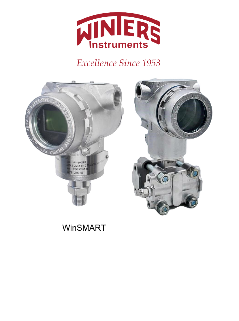
WinSMART
™
LY14 & LY34
Smart Pressure and
Smart Differential Pressure
Transmitter
Operation Manual
Page 2

1.
Outline -------------------------------------------------------------------------------------------------------------------
2
1.1
Introduction------------------------------------------------------------------------------------------------------
2
1.2
Characteristics--------------------------------------------------------------------------------------------------
2
2.
Principle and Wiring Diagram --------------------------------------------------------------------------------------
2
2.1
Principle ----------------------------------------------------------------------------------------------------------
2
2.2
Wiring Diagram-------------------------------------------------------------------------------------------------
3
3.
Transmitter Rotation--------------------------------------------------------------------------------------------------
3
4.
Interface Display ------------------------------------------------------------------------------------------------------
4
4.1
Normal Display -------------------------------------------------------------------------------------------------
4
4.2
Setting Status---------------------------------------------------------------------------------------------------
4
4.3
Keypad -----------------------------------------------------------------------------------------------------------
4
5.
Specific Application and Typical Installation -------------------------------------------------------------------
5
5.1
Typical Installation for Flow Measurement --------------------------------------------------------------
5
5.2
Typical Installation for Liquid Level Measurement ----------------------------------------------------
6
6.
Applications-------------------------------------------------------------------------------------------------------------
7
6.1
Closed Tank-----------------------------------------------------------------------------------------------------
7
6.2
Open Tank-------------------------------------------------------------------------------------------------------
7
7.
Operation Instructions -----------------------------------------------------------------------------------------------
8
7.1
Operation Flow Chart -----------------------------------------------------------------------------------------
8
7.2
System Menu Operation -------------------------------------------------------------------------------------
9
7.3
How to Set Positive Shift and Negative Shift -----------------------------------------------------------
11
7.3.1 Zero Shift and Full Span Shift Operation --------------------------------------------------------
11
7.4
How to set Decimal Point and Minus Value-------------------------------------------------------------
13
7.5
Displayed Variables Settings -------------------------------------------------------------------------------
14
8.
Flow Measurement Settings----------------------------------------------------------------------------------------
15
Operation Manual
LY14 & LY34 INSTRUCTION MANUAL
Index
1
Page 3
LY14 & LY34 INSTRUCTION MANUAL
4-20mA
LY14
Current Loop
CPU
HART®
LY34
Communication
Linear
Display Module
Constant
1. Outline
1.1 Introduction
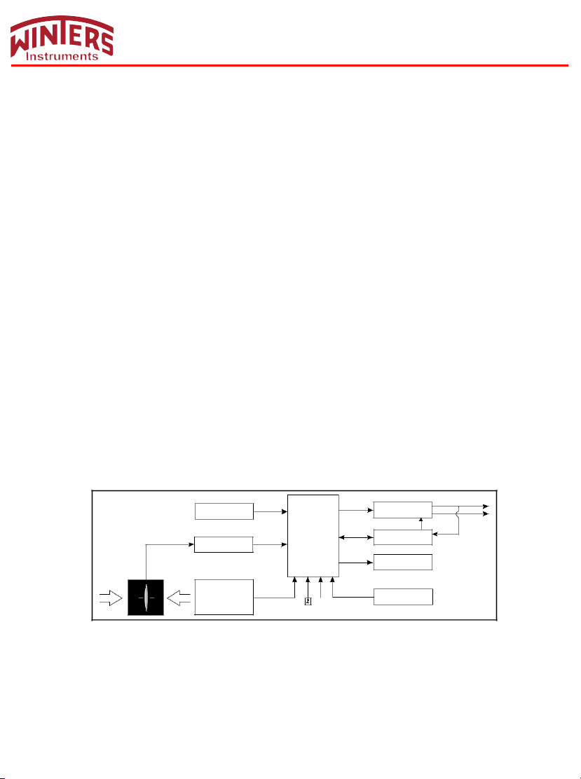
The smart pressure transmitter is a multi-functional digital instrument. It is uniquely designed from advanced
single-chip technology and smart digital technology on the basis of mature and reliable sensor technology.
Its core component is 16-bit single chip whose strong function and high-speed calculation will guarantee the
transmitter’s quality. The whole design focuses on reliability, stability, high-precision and intelligence. It also
meets field industrial application requirements. The software adopts digital signal processing technology,
enhancing transmitter anti-interference ability, zero point stability, Zero Sensitive Capability (ZSC) and
Temperature Sensitive Capability (TSC).
1.2 Characteristics
The smart pressure transmitter has excellent anti-interference ability, zero point stability, Zero Sensitive
Capability (ZSC) and Temperature Sensitive Capability (TSC). It also has HART® communication capability
with optional HART® modules.
2. Principle and Wiring Diagram
2.1 Principle
When pressure or differential pressure is externally applied, the sensor’s resistance will change and be
converted into frequency signals by a digital signal, and then sent to the microprocessor. The microprocessor
will output a current control signal to a current output control circuit after its calculation, turning into 4-20mA
analog current output and display.
2
Page 4
S
Z
0 50 100%
M
LY14 & LY34 INSTRUCTION MANUAL
2.2 Wiring Diagram
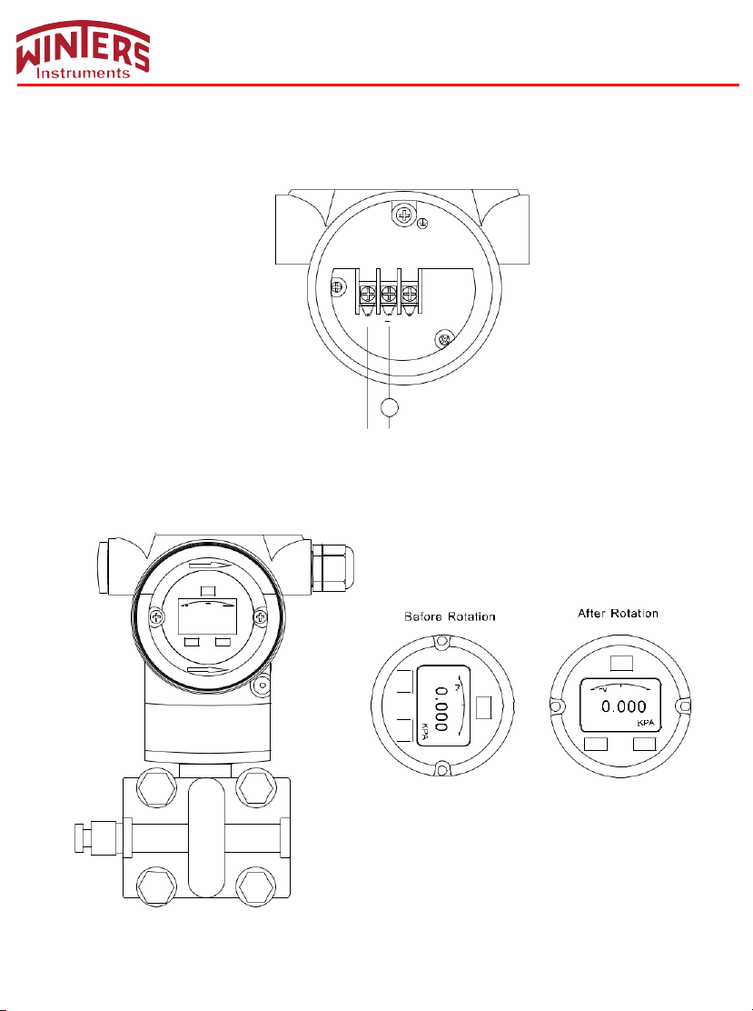
2-wire 4-20mA output.
Z S
+ -
+
mA
-
+ -
9~32VDC
3. Transmitter Rotation
Available clockwise rotation angle: 0-200°; available counterclockwise rotation angle: 0-160°. See figure below:
DG
8.8
S
CW0- 200°
M
PV
0.000
KPA
S Z
CCW0- 160°
Z
DG
8.8
M
50 100%
0
S
Z
DG DG
8.8 8.8
3
Page 5
Code
Code Function
PV
Normal Display (Measuring Status)
%
Percentage
Display measuring unit.
”Special” means customer’s unit can be written
by HART®.
Code
Code Function
2
Window code (“2”: unit selection window)
KPA
Measuring unit
LY14 & LY34 INSTRUCTION MANUAL
4. Interface Display
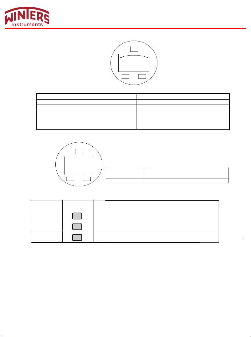
4.1 Normal Display
0 PV
0.000
S
M
50
100%
KPA
Z
This transmitter can be rotated clockwise/counterclockwise 180° for your convenience.
InH2O, InHg, FtH2O, mmH2O, mmHg, PSI, Bar,
mBar, g/cm2, kg/cm2, Pa, kPa, Torr, ATM, MPa,
InH20@4˚C, MH20@4˚C, MH2O, mHg, M, cm,
mm, Special.
4.2 Setting Status
4.3 Keypad
Key Name
SET
MOVE
UP
M
0.000
KPA
2
S Z
Button Sign
M
Z
S
Setting Function
Enter Parameter setting; save configuration; shift to next page
Move the cursor to the right
Increase the values and decimal point position
1. Hold Z button for 2 seconds then release to enter main menu settings.
If there is no response for 10 seconds in the window 0, it will return to the normal display automatically.
If there is no response for 2 minutes in the non-window 0, it will return to the normal display automatically.
2. Hold M + Z buttons for 5 seconds then release to enter menu setting window 6 for zero clearance. Press S
button and choose ”YES” to clear zero.
3. Hold S + Z buttons for 5 seconds then release and enter the menu setting window 7 for zero shift and full span
shift.
Hold Z button for 5 seconds then release to finish Zero Shift; hold S button for 5 seconds then release to finish full
span shift.
4
Page 6
3-way manifold valve
Vent/ Drain plug
Drain valve
Drain valve
LY14 & LY34 INSTRUCTION MANUAL
5. Specific Application and Typical Installation
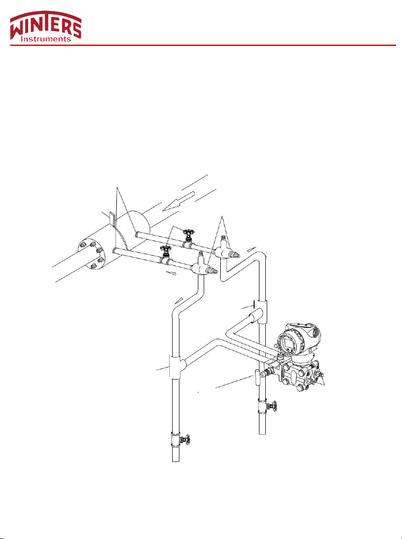
5.1 Typical Installation for Flow Measurement
This illustration shows a typical example for steam flow rate measurement. The differential pressure transmitter is
located below the differential pressure output port of the process pipe.
After piping connections are made, make sure that the connecting pipe, 3-way manifold valve and transmitter
have no pressure leaks. Pipe installation for steam flow rate measurement is as follows:
Differential pressure output port
Orifice
Seal pot
Plate
Main valve
Inclination
Inclination
High-pressure side
Inclination
Tee
Low-pressure side
Tee
5
Page 7
Main valve
Liquid level
Main valve
3-way manifold valve
Vent / Drain plug
Drain valve
Drain valve
LY14 & LY34 INSTRUCTION MANUAL
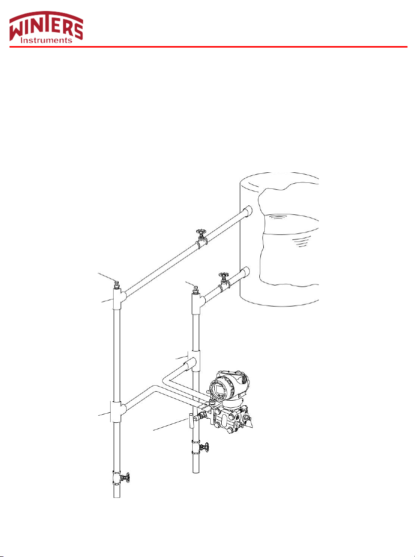
5.2 Typical Installation for Liquid Level Measurement
When using dry-leg method, connect the high-pressure side of the transmitter to the lower part of the tank.
Connect the low-pressure side to the gas-sealing pipe of the tank.
After completing piping connections, check for pressure leaks around the connecting pipe, the transmitter
and 3-way manifold valve. The following shows a typical installation.
Always connect the high-pressure side of this transmitter to the lower part of the tank.
Install this transmitter below the lowest liquid level to be measured.
Gas vent plug
Tee
Low-pressure side
Gas vent plug
High-pressure side
Tee
Tee
6
Page 8
6. Applications
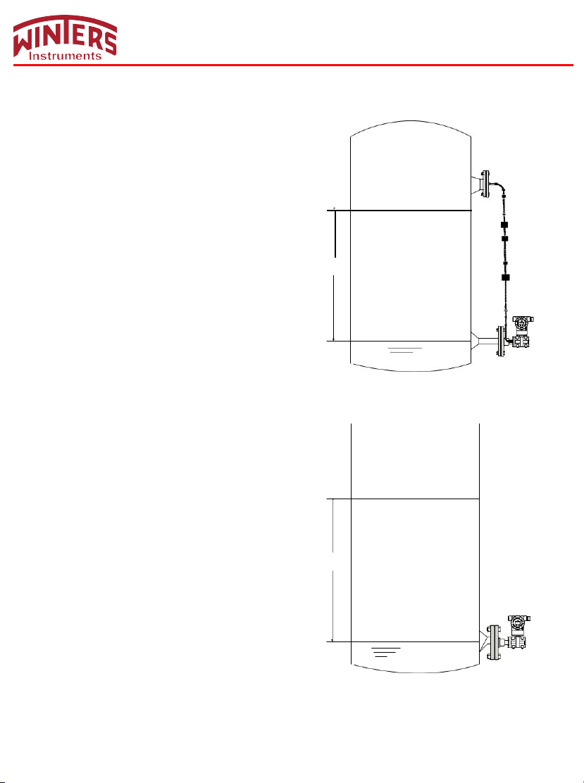
6.1 Closed Tank
When it is a closed tank, there will be pressure inside the tank.
Choose either level transmitter or remote level transmitter
When setting the zero point, make sure the diaphragm area
100% Liquid Level
of high-pressure side is fully wet with measured liquid for
higher accuracy.The center diaphragm of high-pressure side
is the right zero point. See figure:
Variable
Head
6.2 Open Tank
When it is an open tank, the liquid above will be directly in
contact with atmosphere.
Choose a directly-connected pressure transmitter.-
When setting the zero point, make sure the diaphragm
of the high-pressure side is fully wet with measured
liquid for higher accuracy. The center diaphragm of
high-pressure side is the right zero point. See figure:
7
Variable
Head
LY14 & LY34 INSTRUCTION MANUAL
0% Liquid Level
100 % Liquid Level
0 % Liquid Level
Page 9
0
PV
50
100%
0.000
KPA
Z
M
00000
1
Z
S
00002
1
M
0.000
2
KPA
M
Z
0.0000
3
KPA
M
Z
120.00
4
KPA
M
Z
0.0000
5
S
M
Z
0.000
6
NO
M
Z
0.000
8
LIN
M
Z
00000
S
0
M
Z
8
LY14 & LY34 INSTRUCTION MANUAL
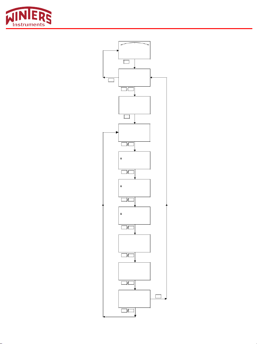
7. Operation Instructions
7.1 Operation Flow Chart
Page 10
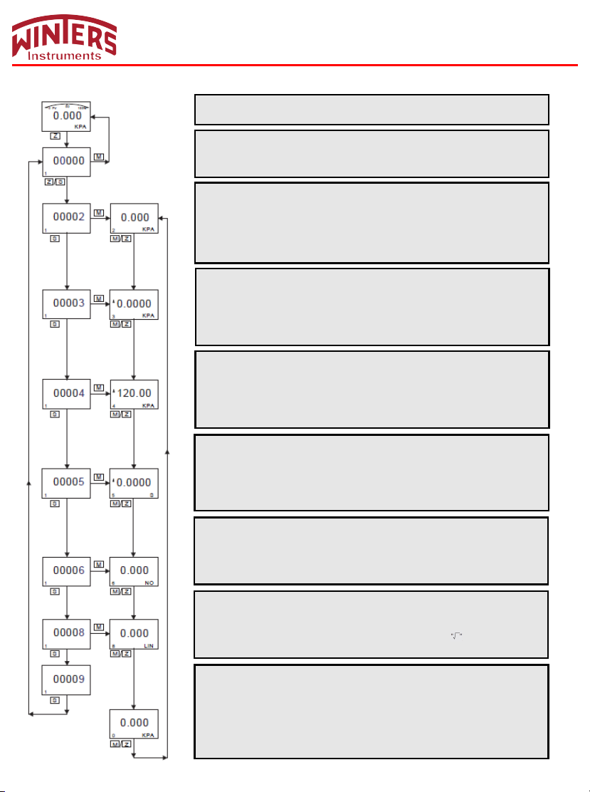
Normal Display
Code Setting Window (Code 1)
Press
If there
LY14 & LY34 INSTRUCTION MANUAL
Unit Setting Window (Code 2)
7.2 System Menu Operation
Hold Z for 2 seconds, then release to enter main setting menu.
Press Z to move cursor button and press S to change the value,
If there is no response for 10 seconds, it will return to the normal display
automatically.
Press M to enter unit selection, then press S to activate the cursor and press
S again to select unit as follows: InH2O, InHg, FtH2O, mmH2O, mmHg, PSI,
Bar, mBar, g/cm2, kg/cm2, Pa, kPa, Torr, ATM, MPa, InH20@4˚C, H20@4˚C,
MH2O, mHg, M, cm, mm, Special. (”Special” means customer’s unit can be
written by HART®.) Press M/Z to confirm and enter next window Code 3.
Lower Range Limit Setting Window (Code 3)
Press M to enter Lower Range Limit Setting Window, and then press S to
activate cursor. Press Z again to change the symbol to ”-”. Or press Z directly
to move cursor and then press S to change value. When cursor moves to the
right, press Z and all decimal points will flash. At this time, press S to change
decimal position. Press M or Z to confirm and enter next window Code 4.
Upper Range Limit Setting Window (Code 4)
Press M to enter Upper Range Limit Setting Window, and then press S to
activate cursor. Press S again to change the symbol to ”-”. Or press Z directly
to move cursor and then press S to change value. When cursor moves to
right, press Z and all decimal points will flash. At this time, press S to change
decimal position. Press M or Z to confirm, and enter next window Code 5.
Damping Setting Window (Code 5)
Press M to enter Damping Setting Window, and then press S to activate
cursor, and press S again to change the symbol to ”-”. Or press Z directly to
move cursor and then press S to change value. When cursor moves to right,
press Z and all decimal points will flash. At this time, press S to change
decimal position. Press M or Z to confirm, and enter next window Code 6.
Damping Setting Window (Code 6)
Press M to enter Zero Calibration, and then press S to activate cursor, and
press S again to choose whether to calibrate zero or not.
1. YES 2. NO
Press M or Z to confirm, and enter next window Code 8.
Damping Setting Window (Code 8)
Press M to enter Output Setting, and then press S to activate cursor, and
press S again to choose output type.
1. LIN 2. SQRT (Choose SQRT, normal display will show )
Press M or Z to confirm, and enter next window Code 0.
Exit Window (Code 0)
1. If there is no response for 10 seconds, it will return to the normal display
automatically.
2. Press M or Z to confirm, and enter next window Code 2.
3. Press S to activate and press M to enter window Code 1 to set window-code
input.
4. Input “00000/000007/000009” in window Code 1, and press M to return
Normal Display.
9
Page 11
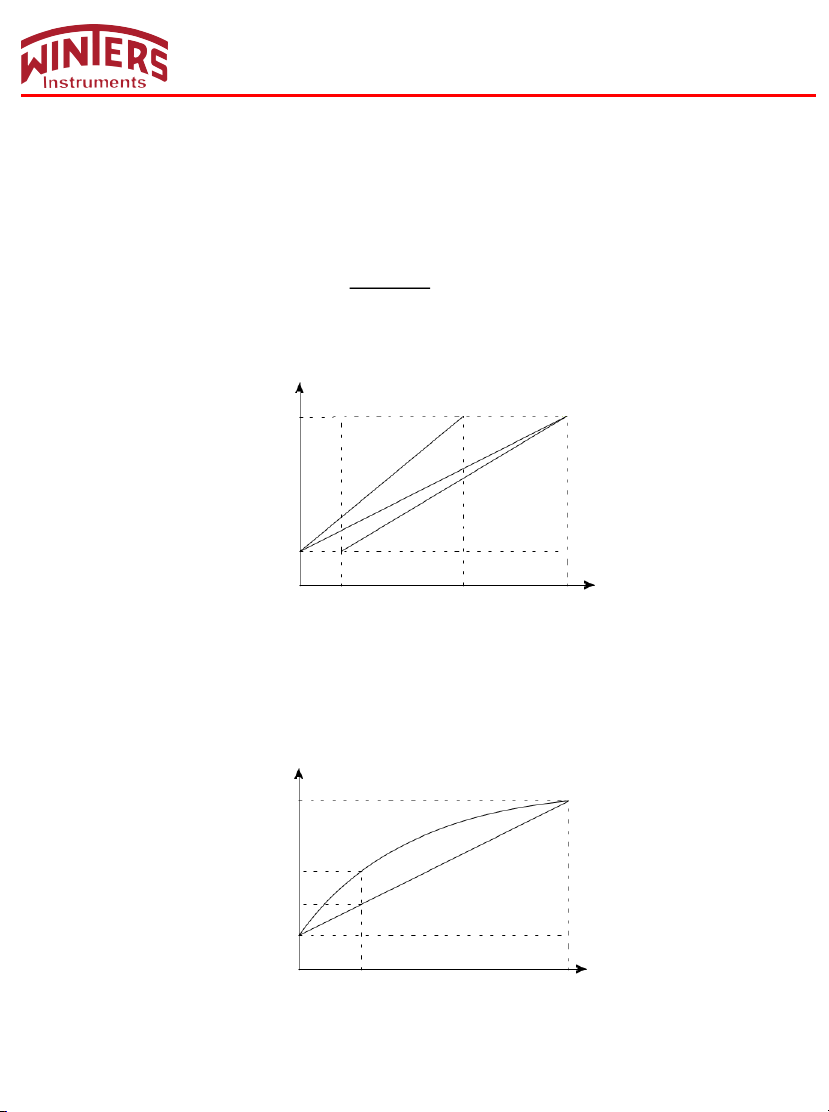
I =
P-MA
×
16mA+4mA
ME-MA
20
Current value (mA)
1
2
4 3
Pv (kPa)
Xmin1 Xmin2
Xmax1
Xmax2
LY14 & LY34 INSTRUCTION MANUAL
(1) Upper/Lower Range Limit Correspondence to 4-20mA
In settings, if necessary, lower/upper range Limit will be given standard current value (4mA/20mA) respectively.
Preconditions: Two reference voltages should be supplied by process or pressure transmitter. After
setting pressure transmitter, actual setting range might be different from the range marked in measuring plate.
For different serial number and measuring range, turndown ratio can be up to 10:1.
Measuring pressure is linearly related to output current. Current value can be calculated from given formula
below. I means output current, P measured pressure, ME upper limit value and MA lower limit value.
Actually because of change of measuring demands or conditions, transmitter’s range needs to be changed
too. However, changing range means changing slope of transmitter’s input/output, like from curve 1 to curve
2, it means upper range limit increasing adjustment; from curve 2 to curve 3, it means lower range limit increasing
adjustment. See figure below:
(2) Damping Settings
Available setting time is 0-32s. The bigger this value is, the more stable the measuring value will be
(Flunctuation will be more moderate). Increasing damping time will also lead to signal delay.
(3) Zero Calibration
Because of zero drift, the measured zero point will not be 0. Zero calibration enhances better measuring accuracy.
(4) Output Settings
e.g. Transmitter’s pressure range “0- -100kPa”, if output setting as “lin”, current output will be curve 1.
If set “sqrt”, current output will be curve 2. For example, if pipe pressure as 25kPa, under “sqrt” condition
current output will be 12mA.
Current Value (mA)
20
12
8
4
0 25 100
2
1
Pv (kPa)
10
Page 12
LY14 & LY34 INSTRUCTION MANUAL
7.3 How to Set Positive Shift and Negative Shift
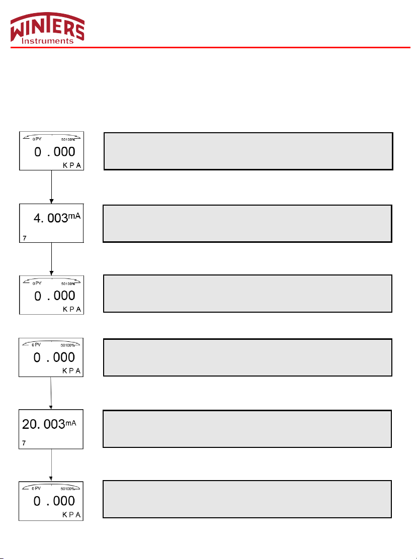
7.3.1 Zero Shift and Full Span Shift Operation
This is a hidden window, so it will not display if you directly input code 7 in the code window. You have to hold S + Z
for 5 seconds until it displays.
Normal Display
Hold S + Z for 5 seconds and then release to enter menu-setting window 7, setting the zero
shift and full span shift.
Z + S
Zero Shift
Hold Z for 5 seconds and then release to nish zero shift. If there is no key operation within 2
minutes, it will return to normal display automatically
Normal Display
Z+S
Normal Display
Hold S + Z buttons for 5 seconds then release and enter window 7 for zero shift and full span
shift.
Full Span Shift
Hold S for 5 seconds, and release to nish full-span shift. If there is no key operation within 2
minutes, it will return to normal display automatically.
Normal Display
11
Page 13
20
Current Value (mA)
1
2
4
Pv (kPa)
0
15
80
95
LY14 & LY34 INSTRUCTION MANUAL
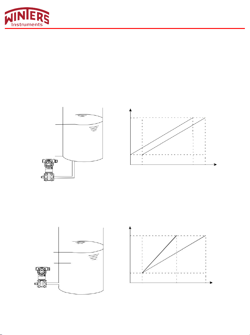
When it comes to actual measurement, the initial measuring point needs to be shifted to a certain value
(positive or negative). This is called zero shift and full span shift.
(1) Zero Shift (Elevated Span / Suppressed Span)
After zero shift, measuring range will change toward positive (increase) direction, namely positive shift. For
example, pressure transmitter is installed at point A, the liquid head AB that is formed by medium that
comes into pressure-guiding pipe will
AC’s pressure (measured pressure BC plus liquid head’s pressure). At this time, when liquid level is at
point B, give positive zero shift to transmitter, the initial value of corresponding 4
point A to point B, making it convenient to control the application.
If transmitter’s range is 0~80kPa and AB pressure of pressure guiding pipe is 15kPa, after zero shift,
change wil
l be like figure below: curve 1 to curve 2.
C Liquid level
send a pressure to transmitter, turning the measuring result into
-20mA will move from
S Z
0.000
B
A
(2) Full Span Shift
After full span shift, measuring range will change toward negative (decrease) direction, namely negative
shift. For example, when pressure transmitter measures liquid level’s pressure and the operator just needs
the pressure of level AB (lower than AC pressure), full span shift can start.
If transmitter’s range is 10~100kPa and AB pressure of liquid level is 65kPa, after full span shift, change
will be like figure below: curve 2 to curv
C
Liquid level
B
A
e 1.
Current value (mA)
20
1 2
4
0 10 65 100
Pv (kPa)
12
Page 14
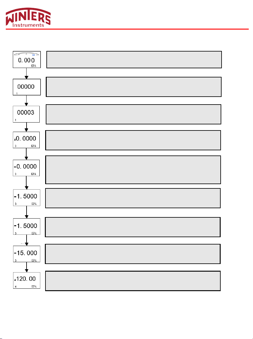
7.4 How to set Decimal Point and Minus Value
Example: Set zero as “-15kPa”
Normal Display
Hold Z for 2 seconds and then release to enter main menu setting.
Z
Code Setting Window (Code 1)
Press Z to move cursor button and press S to change value. If there is no key operation within
10 seconds, it will return to normal display automatically
Z/S
Code Setting Window (Code 1)
Press S to change value and set numeric value to 00003, and then press M to enter zero
M
S
Z
Z/S
setting.
Zero Setting Window (Code 3)
Press M to enter zero setting.
Zero Setting Window (Code 3)
Press S to activate cursor.
Press S again to change symbol as “-” (”-” symbol will be added to the furthest left position).
Press Z to move cursor position, and then press S to change the numeric value.
Enter next window:
Zero Setting Window (Code 3)
Press Z to move cursor. When the cursor moves furthest to the right, continue to press Z until
all the decimal points ash. Enter next window:
LY14 & LY34 INSTRUCTION MANUAL
Z
M
Zero Setting Window (Code 3)
Press S to change decimal position after all decimal points ash. Press S twice to enter the
next window:
Zero Setting Window (Code 3)
Press M to conrm and enter next window Code 4.
Span Setting Window (Code 4)
13
Page 15
0
PV
50
100%
0.000
0 PV
50
100%
0
100%
0.000
0
100%
0.000
0
100%
0.000
0
100%
0.000
LY14 & LY34 INSTRUCTION MANUAL
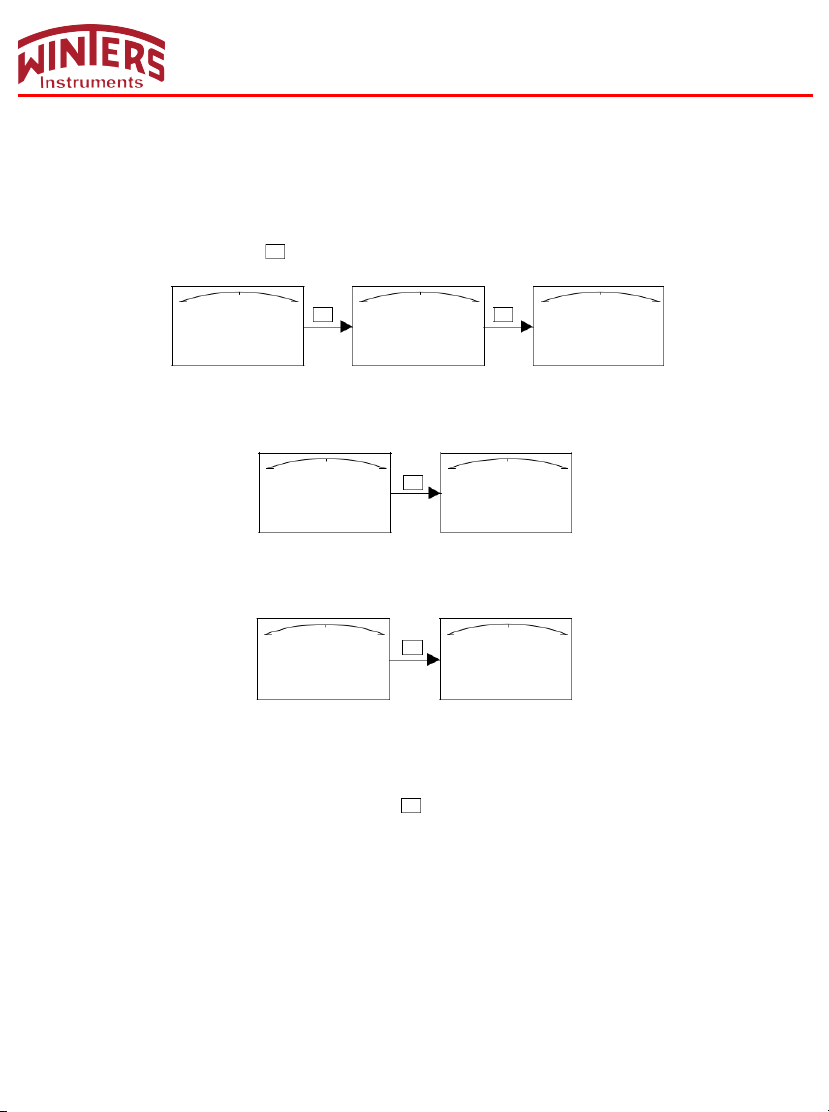
7.5 Displayed Variable Settings
LCD can be set to display "Process Variable", "mA value", "%". These 3 can be displayed either constantly,
one of them, or alternatively 2 of them.
If first displayed variable and second displayed variable are the same, this will be constant display.
If first displayed variable and second displayed variable are different, this will be alternative display (interval
is 4 secs).
In normal display interface, hold
30 KPA
S
button to change displayed variable (In bottom left corner, function code is 30.).
S
0.000%
30
PV
0
S
50 100%
0.000
30
mA
Different variables in normal interface means alternative display, for example, “process variable” and “mA
value” display alternatively (first variable: “process variable”; second variable: “mA value”).
50
PV
S
50
PV
mA
KPA
Same variables in normal interface means constant display, for example, “process variable” displays
constantly (first variable and second variable are both the same: “process variable”).
50
PV
S
50
PV
KPA
KPA
e.g. 1 When displayed contents are “process variable” and “mA value”, which means alternative
display, to change to constant display and make displayed content as “process variable”, you need to change
“mA value” to “process variable”, namely, making the first variable same as the second.
Procedure: When screen displays “mA value”, hold S and do not release until screen shows “process variable”.
Namely changing “mA value” to “process variable”. At this time, screen will constantly display “process variable”.
e.g 2 When displayed contents are “process variable”, which means constant display, to change to
alternative display and make displayed content as “process variable” and “mA value”, you need to change
“process variable” to “mA value”, namely, making the first variable different from the second.
Procedure: When screen displays “process variable”, hold S
value”. Namely changing “process variable” to “mA v
“process variable” and “mA value”.
and do not release until screen shows
alue”. At this time, screen will alternatively display
“mA
14
Page 16
LY14 & LY34 INSTRUCTION MANUAL
8. Flow Measurement Settings
Differential pressure transmitter measures flow and displays flow rate. As long as flow range and differential
pressure’s range is certain, flow can be measured and flow rate can be displayed.
If your purchased product has HART® communication function, you can set parameters by yourself.
Let’s take an example of HART® function settings
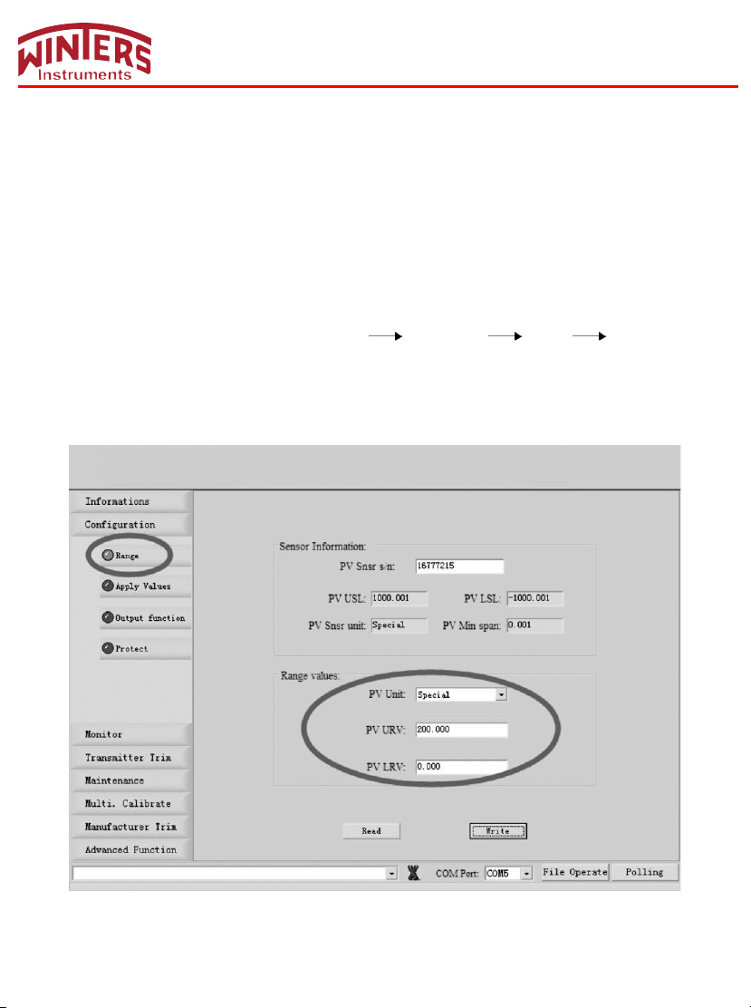
EX.1: Differential pressure’s range is 0~500mbar and corresponding flow range is 0~200M3/H.
Steps: 1. Build Hart® communication, Run software.
2. In Configuration column, single click Range Range values PV Unit Special.
3. Input upper range value and lower range value, namely
4. Click “write” to save settings.
“PV URV”=200.000 and “PV LRV”=0.000.
Shown as below:
15
Page 17
LY14 & LY34 INSTRUCTION MANUAL
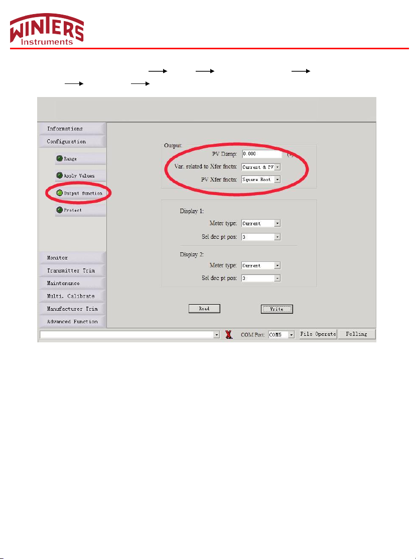
5. In Configuration, click “Output func” “Output” Related Var.of Xfer fnctn choose “Current
and PV” PV Xfer fnctn choose “Square Root”.
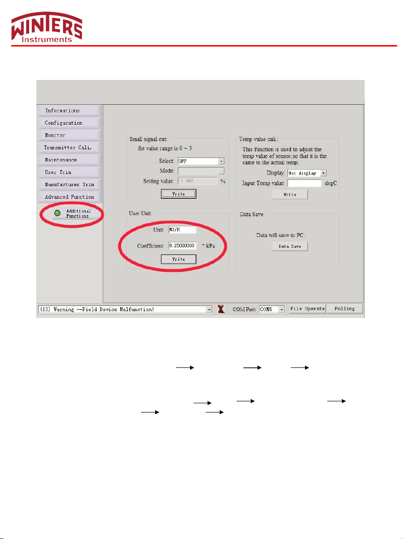
6. In “User Unit”, set it as “M3/H”.
7. Input “Coefficient” value.
The calculation formula of Coefficient value =△P(kPa)/ Max
Flowrate. 500mbar=50kPa
Now coefficient value is =50/200=0.25 and you should input 0.25 in Coefficient.
8. Click write to save settings.
16
Page 18
LY14 & LY34 INSTRUCITON MANUAL
Shown as below:
Note: If actual value and displayed value are different, trim coefficient value.
EX.2: Differential pressure’s range is 0~6000mmH2O and corresponding flow range is 0~300NM3/H.
Steps: 1. Build Hart® communication. Run sof tware.
2. In Configuration column, click Range Range values PV Unit Special
3. Input up range value and low range value, namely “PV URV”=300.000, “PV LRV”=0.000.
4. Click “write” to save settings.
5. In Configuration column, click “Output func” Output Related Var.of Xfer fnctn
choose “Current and PV” PV Xfer fnctn choose “Square Root”.
6. In “User Unit”, set it as “NM3/H”.
7. Input Coefficient value.
The calculation formula of Coefficient value =△P(kPa)/ Max
Flowrate. 6000mmH2O=58.84kPa
Now coefficient value is =58.84/300=0.196 and you should input 0.196 in Coefficient.
8. Click Write to save settings.
17
 Loading...