

WinterGreen IM-90, IM-130, IM-220, IM-330 Owner's Manual
OWNER’S MANUAL
Installation and
Operating
Instructions for
Models:
IM-90, IM-130,
IM-220, IM-330
WinterGreen Wood Furnaces have been
tested and are certified to meet UL standard
391 for safety for Solid Fuel Burning Indoor
Heating Appliances
IMPORTANT. KEEP THESE INSTRUCTIONS. DO NOT THROW AWAY.
BE SURE TO READ THIS MANUAL AND KEEP FOR FUTURE REFERENCE.
WinterGreen Wood Furnaces
3015 West Main Street, Parish, NY 13131
Email us: sales@homegrownheat.com
Visit us at: www.homegrownheat.com
Version: 8/09

TABLE OF CONTENTS
Section Page
Furnace Serial Number – Recording Information 4
Warnings and Safety – Installation 5
Warnings and Safety – Operation 6
Risk of Fire - Explosion 7
Safety Label Locations 8
Furnace Introduction
Firebox technology 9
Combustion chamber 9
Heat exchanger 9
Water tube design 9
Wood gasification & Combustion Chamber 10
Furnace Unloading and Moving
Safety 11
Unloading furnace from pallet 11
Lifting the furnace from the Bottom 12
Lifting the furnace from the top with a spreader bar 13
Lifting the furnace from the top with slings 13
Floor requirements 14
Furnace Specifications 15
Furnace Component List 16
Furnace Installation – Location
Mounting on a cement or masonry base 17
Clearances to combustible surfaces 18
Connecting to existing ductwork 18
Chimney Installation
Chimney Regulations 19
Furnace connection to a factory built chimney 20
Furnace connection to a Masonry Chimney 21
General Rules for chimneys 22
Digital Temperature Controller
Feature description 23
Operation & setting temperature 24
Error messages, settings & alarms 25
Furnace Startup
Cold startup – checking the furnace 26
Cold startup fire 26
Factory setting for damper 27
Runaway Fire 27
Furnace – Primary Fire
Determining the appropriate fire size 28
Normal operating temperature 28
Furnace - Ash Disposal
Disposal of ashes 29
Access to ash pan 29
Loading the Furnace
Warnings 30
Wood loading procedure 31
Proper wood loading height in the furnace 32
Loading wood into the furnace 33
Furnace burning tips 33
Wood Selection
Efficiency 34
Best wood to burn 34
Harvesting 34
Wood selection chart 35

TABLE OF CONTENTS
Section Page
Draft Inducer and Barometric Damper
Draft Inducer location and installation 36
Draft Inducer-installation on stove pipe 37
Draft Inducer-Electrical outlet on furnace 38
Barometric Damper location and Installation 39
Maintenance 40
Draft Setup
What is draft 41
What is the Draft Inducer and Barometric Damper 41
Manometer and where to test 42
Barometric Damper setup 42
Draft Inducer setup 43
Measuring and adjusting the flue draft 44
Maximum draft setting 45
Negative Air – Make-up Air
Negative air problems 46
Supplying Make-up air 46
Determining the volume of fresh air 46
Confined and unconfined space 47
Plumbing Installation
System configurations 48
Filling the system 48
Closed System – basic plumbing configuration to furnace 49
Open System – basic plumbing configuration to furnace 50
Closed System – basic plumbing configuration to boiler 51
Side Arm Heat Exchanger (Hot water tank) 52
Furnace Plenum Heat Exchanger 53
Plumbing components and functions 54
Wiring and Controls
Basic wiring and controls 55
Wiring schematic 56
Furnace control panel 57
Power Failures – System Backup
Overheat protection during a power failure 58
Power outage instructions 58
Battery Backup power supply (Schematic) 59
Installing a back-up generator 60
System backup – Heat from main furnace or boiler 60
Thermal Spike Protection
Why have thermal spike protection 61
Thermal spike protection methods 61
Maintenance – Furnace
End of season and general maintenance 62
Flushing the system 62
Firebox refractory cracks 62
Maintenance – Chimney
Chimney inspection and cleaning 63
Creosote 63
Chimney Fire 64
Troubleshooting Guide 65
Warranty 66
FURNACE SERIAL NUMBER
Locate the serial number and model number of your WinterGreen Furnace on the unit and record
them in the space provided in the label below. (See section: “Safety Label Locations”) for the
location of the Manufacturer’s Decal on the furnace.
Have this information available when contacting your WinterGreen Dealer for warranty, service
or technical information.
WinterGreen
Manufactured for WinterGreen Wood Furnaces by SJV Inc. Fort Kent, Maine, USA
WARNINGS & SAFETY
INSTALLATION
Read and understand all warnings, safety instructions and information provided in this
manual. If your Furnace is not installed properly a house or building fire may occur.
Furnace installation must conform to National Fire Protection Association (NFPA) installation standards No.89M, 90B, 211, 70 (National Electrical Code) and local building and fire code standards.
Check with local authorities for the code requirements in your area.
Chimney installation must conform to National Fire Protection Association (NFPA) Standard 211
and local building and fire code requirements. Check with local authorities for the code requirements
in your area.
DO NOT CONNECT furnace to an aluminum “Type B” gas vent. This is unsafe. Use an approved
masonry or CSA/UL approved, "Class A" Residential Type Building Heating Appliance Chimney.
DO NOT USE A CHIMNEY CAP.
DO NOT connect furnace to a chimney flue shared with another appliance.
Ensure your chimney is safely constructed and in good repair. Have the chimney inspected by a
qualified technician.
Installation should be made by a qualified heating equipment installer (one who is engaged in and is
responsible for, or is thoroughly familiar with the installation and operation gas, oil and solid fuel
burning heating appliances; that is experienced in such work and familiar with all building requirements and/or fire codes of the authority having local jurisdiction.
DO NOT INSTALL THIS FURNACE IN A MOBILE HOME. Install the Furnace outside in a covered
building and pipe the hot water heat into the home.
Always connect this furnace to an approved chimney and vent to the outside, never vent to another
room or inside a building.
Observe all clearances as specified in this manual, especially those for combustibles materials.
DO NOT operate the furnace while under the influence of alcohol or drugs.
The furnace has stainless steel and painted surfaces which are very durable, although rough handling or abuse will cause premature failure of their protective qualities. To maintain a long lasting
finish, handle with reasonable care. Clean surfaces regularly with soap and water or stainless steel
cleaner. ONLY WHEN THE FURNACE IS COOL! Paint discoloration will occur if the furnace is overfired.
While in operation, keep the feed door, ash tray door closed and secured at all times, except when
tending the fire.
Operate the furnace draft with no less than 0.005” WC or no more than 0.07” WC
FURNACES ARE HEAVY!
Models can be from 2400 lbs. to 3800 lbs. Check specifications and know the weight of your unit. In order to prevent personal injury, make sure you have the proper equipment and manpower to unload,
move and position your boiler safely.
Continued on next page…
WARNINGS & SAFETY
OPERATION
To prevent injury, always wear protective clothing, leather hearth
gloves and eye protection while tending the furnace fire. NEVER
TOUCH THE FURNACE WITH BARE SKIN
Do not over-fire the furnace. Over firing will occur if the feed door or
ash door is left open during furnace operation. A dangerous fire hazard condition may result!
Keep the furnace area clear and free from all combustible materials,
wood chips, gasoline and all other flammable vapors and liquids.
DO NOT any use chemicals, charcoal lighter fluid, gasoline or any
other type of flammable liquids to start the fire.
Do not burn coal, use only solid seasoned whole wood.
Do not allow ashes to accumulate higher than the bottom of the
draft holes in the firebox.
Open firebox door slowly when loading the furnace.
Do not install the warm air supply outlet (Heat Exchanger) of the furnace to the cold air return inlet of the central home furnace because
a possibility exists of components of the central furnace overheating and causing the central furnace to operate other than intended.
While the furnace is in operation, extreme care should be taken to
avoid contact with the unit as high surface temperatures may result
in a burn injury. Special care should be taken if children are present
in the area of the furnace, they should be kept a safe distance away
from the unit and supervised at all times. IT IS RECOMMENDED
THAT A CHILD PROOF BARRIER BE INSTALLED AROUND THE PERIMETER OF THE UNIT AT A SUITABLE DISTANCE TO ENSURE
THERE IS NO POSSIBILITY OF CONTACT OR POTENTIAL INJURY.
Continued on next page…
WARNINGS & SAFETY Continued:
RISK OF FIRE
NEVER OPERATE THE FURNACE WITH THE DRAFT DOOR
BLOCKED OPEN!
DO NOT OPERATE WITH THE FUEL LOADING OR ASH REMOVAL DOORS OPEN!
DO NOT STORE FUEL OR OTHER COMBUSTIBLE MATERIAL
WITHIN THE MARKED INSTALLATION CLEARANCES OF
FURNANCE.
INSPECT AND CLEAN FLUE AND CHIMNEY REGULARLY.
DO NOT OPERATE WITH FLUE DRAFT EXCEEDING .07” WATER
COLUMN.
RISK OF FIRE OR EXPLOSION
DO NOT BURN GARBAGE, GASOLINE, DRAIN OIL OR ANY
OTHER FLAMMABLE FLUIDS.
HOT SURFACES
KEEP CHILDREN AWAY FROM FURNACE.
DO NOT TOUCH HOT SURFACES DURING FURNACE OPERA-
TION. MAXIMUM DRAFT OF FURNACE IS MARKED ON MANUFACTURER’S NAMEPLATE.
WARNINGS & SAFETY
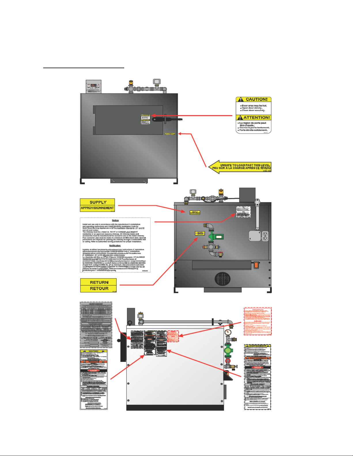
SAFETY LABEL LOCATIONS:

FURNACE INTRODUCTION
Congratulations on your purchase of a new WinterGreen Hydronic Wood Furnace. The WinterGreen Furnace when properly installed and maintained will give you many years of dependable
wood burning service.
To ensure a safe and proper installation of your WinterGreen Hydronic Furnace, you should:
1) Have your furnace installed by a reputable contractor that has experience with the installation of this
type equipment, has knowledge with Solid Fuel Heating Appliances and be familiar with all local fire
and building codes.
2) Read carefully and use the information that is provided in this manual.
How the WinterGreen Hydronic Wood Furnace Works
Firebox Technology:
As wood burns, it begins boiling out moisture at 100˚C/212˚F. The wood starts to change its chemistry at
400-600˚F and begins releasing volatile gases as it breaks down. Those gases contain 50-70% of available energy from the wood. Most furnace designs allow those gases to escape out of the stack, wasting
energy. Our Wood Furnaces are manufactured with a refractory fire chamber surrounded by three
inches of high temperature insulation and an airtight stainless steel “skin”. The fire box temperature exceeds 1500˚F and “skin” temperature is less than 100˚F. The water tube pressure vessel removes both
radiant and convective heat. The heat must travel down past the vessel to the exhaust port, heating the
incoming combustion air on the way. The exhaust temperature is below 300˚F. Once the fluid reaches
the set temperature, the draft is closed and the fire is completely extinguished; it does not smolder. Because the thermal mass in the refractory stays above the flash point the fire always re-ignites when the
furnace calls for heat again.
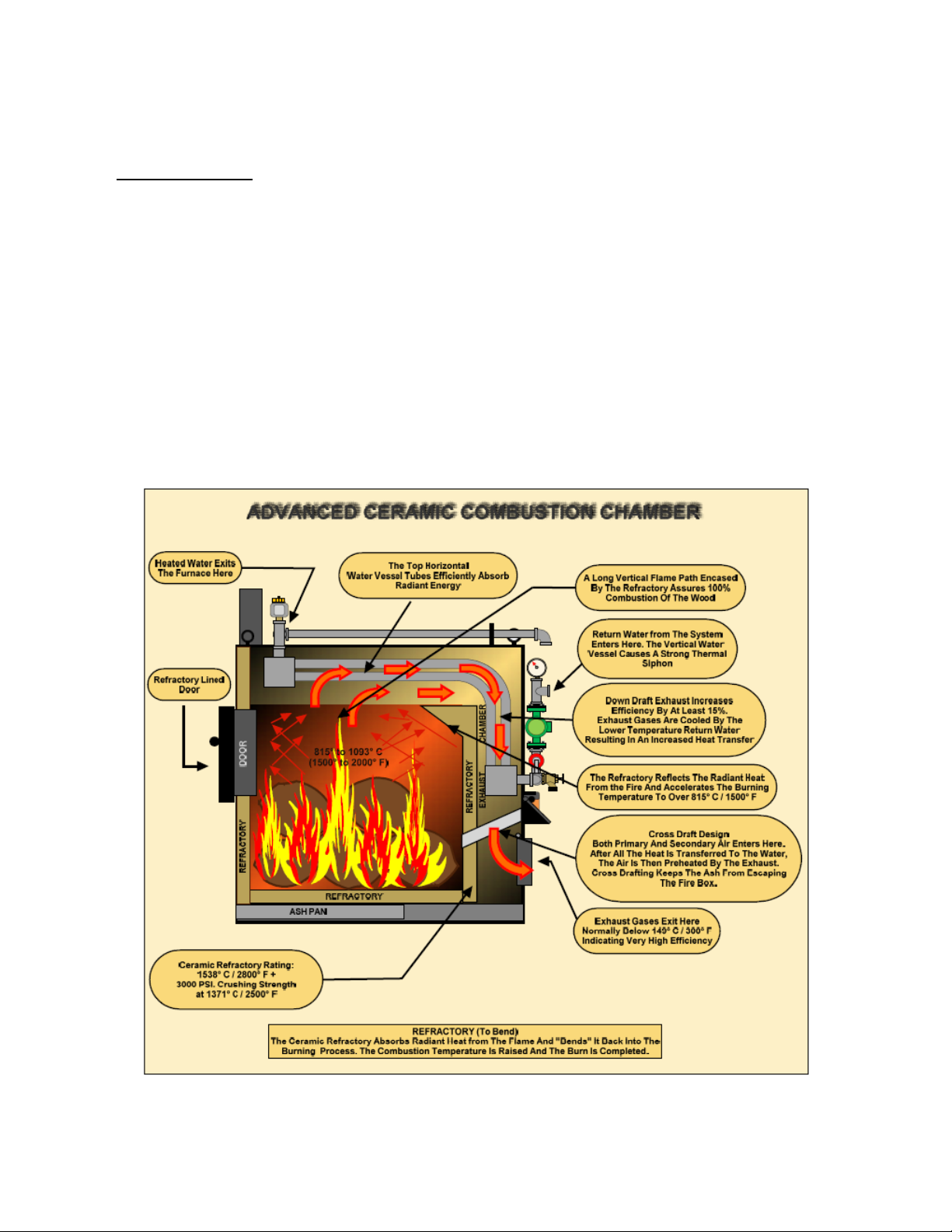
Combustion Chamber:
These Wood Furnaces have several unique features that enable them to achieve higher efficiency and
cleaner burns than other wood Furnaces. The refractory combustion chamber ensures a very high combustion temperature and a long flame path with enough turbulence to complete the burning of all gases.
Once the wood gases are completely burned, the hot gases enter the heat exchange area.
Heat Exchanger:
The heat exchanger is a down draft system where the exhaust exits the unit below the entrances of the
cold water and the draft air supply. Because of the differential between the incoming cold water temperature and the exhaust temperature, thermal transfer is increased. The heat in the exhaust is transferred to the water and warms it as it enters the unit, while also decreasing the exhaust temperature. As
the exhaust continues downward, the I coming draft air is also heated after all the available heat has
already been put into the water. The heate draft air increases the combustion temperature in the refractory chamber without taking heat from the combustion process.
Water Tube Design:
The Furnaces have a water tube design (Pressure Vessel) which absorbs much more heat per square
inch than fire tube furnaces, withstands much more pressure, and also holds much less water so it responds more quickly. Because of limited water storage, water tube furnaces are much safer than fire
tube furnaces.
Continued on next page…
FURNACE - INTRODUCTION Continued:
Wood Gasification
Wood gasification is the process of heating wood in an oxygen-limited chamber until volatile gases
(carbon monoxide, hydrogen, and oxygen) are released from the wood and combusted. Heating the
wood to the temperature range of 400-600 degrees releases most of the gases. The emitted wood
gases are then superheated and mixed with air for complete combustion, leaving little or no ash, and the
heat produced is transferred to the boiler for heating.
This process takes place in two stages, through the cross draft combined with the very high temperatures of the refractory (1500-2000 degrees). The extreme radiant energy from the refractory raises the
wood temperature for gasification, while limiting the oxygen in the primary zone. As the gases rise, the
preheated draft air combines with them and completes the combustion. The long flame path combined
with the turbulence and reverse flow assures complete combustion. During each off-cycle the radiant
heat from the refractory combined with the lack of oxygen prepares the wood for the next cycle.
FURNACE – UNLOADING & MOVING
To Prevent Personal Injury, WinterGreen Recommends:
The use of a suitable Forklift Truck with a capacity rating of at least 5000lb with 5-6 ft forks and is
capable of unloading, lifting and transporting the furnace unit to the determined installation location
safely.
That you have sufficient manpower and proper equipment available to assist in moving and installation of the furnace.
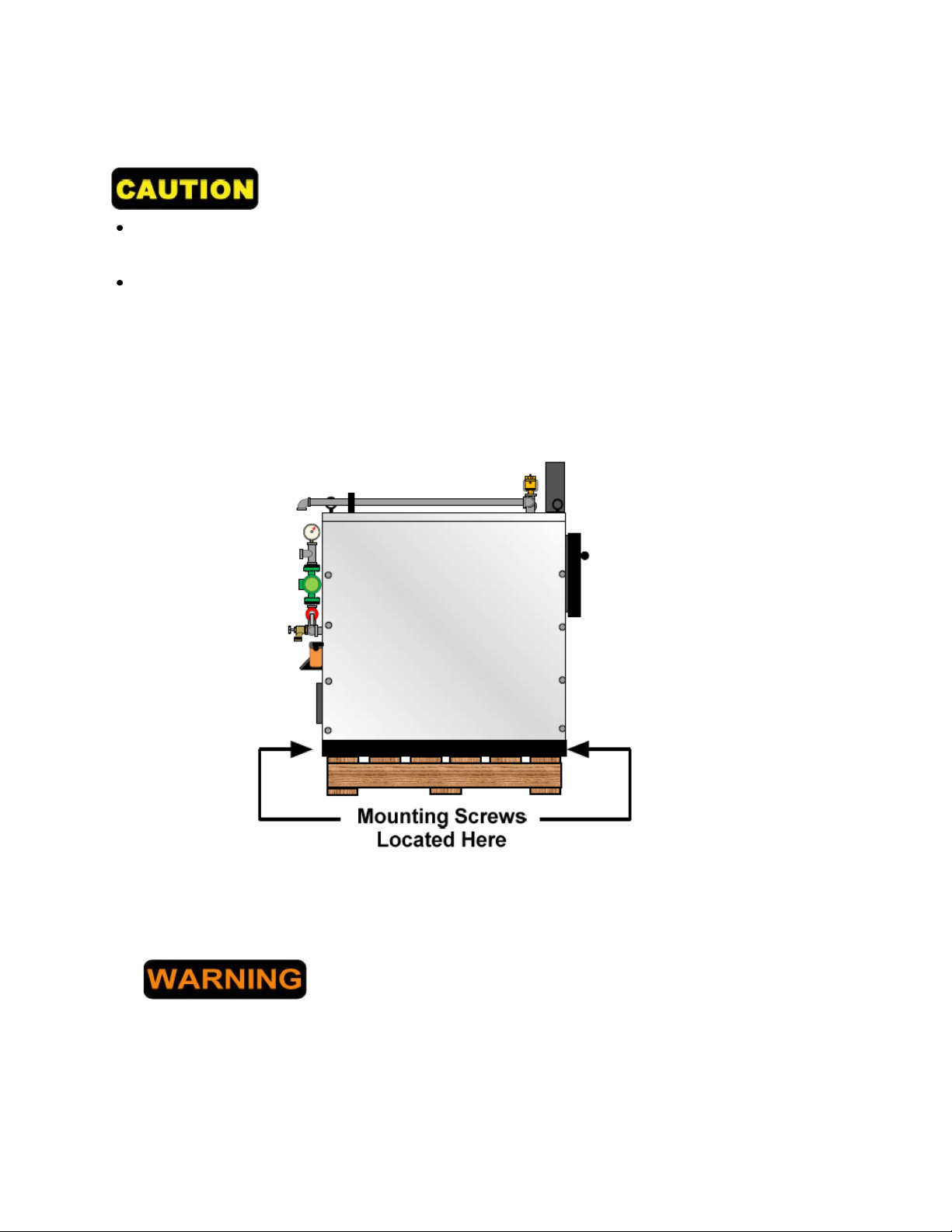
The WinterGreen Furnace comes mounted on a wooden pallet to protect it during shipping. To detach
the furnace from the pallet, remove the 4 (four) anchoring screws located on each corner of the base of
the unit that secure it to the pallet.
WinterGreen Furnaces are heavy, be sure you know the weight your going lift.
WinterGreen recommends that the furnace be moved by a professional equipment mover who is knowledgeable and experienced in
the rigging and moving of heavy equipment. Damage can occur to
the furnace refractory if the unit is dropped. An experienced professional can ensure the installation will be safe and damage free.
Continued on next page…
FURNACE – UNLOADING & MOVING Continued:
Methods of moving the Furnace
The furnace has been designed it to be lifted and transported using a fork lift truck utilizing 2 (two) different methods.
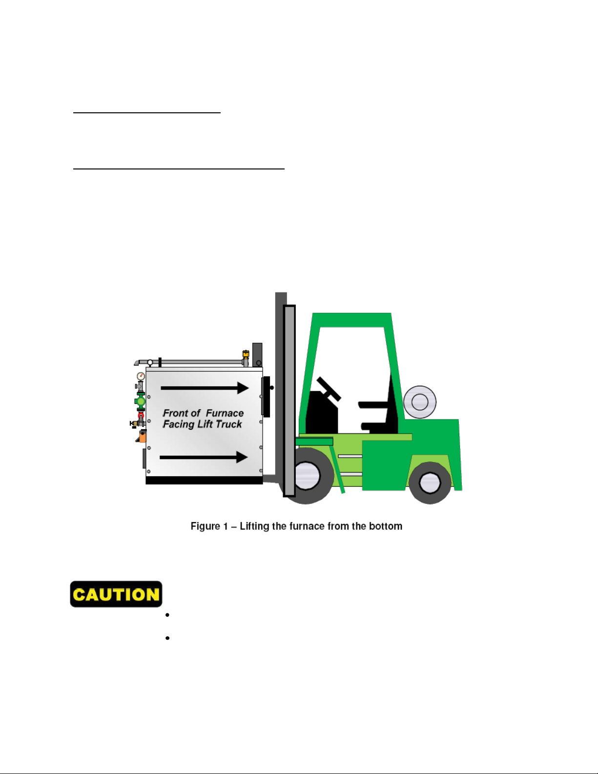
Method 1: Lifting the furnace from the bottom
When moving the furnace from the bottom it is important that the forks be spread as wide as possible to
fit between the base plates .The unit should be centered on the forks so as the load is safely distributed
and the furnace is stable. To prevent damage to the piping and components mounted on the back of the
furnace, the front of the furnace (Loading door side) should face the lift truck. (See figure 1) This is important should the furnace contact the lift truck during the installation. Keep the load level while lifting
and only raise the unit as high as necessary to allow safe movement. Avoid any sudden jerky movements and maneuvers, drive slowly and make any turns with caution.
Never stand under or in the path of the load while moving the furnace!
The operation of a fork lift truck should be performed by a professional
driver who has been trained in the safety and handling of this type of
vehicle.
Continued on next page…
FURNACE – UNLOADING & MOVING Continued:
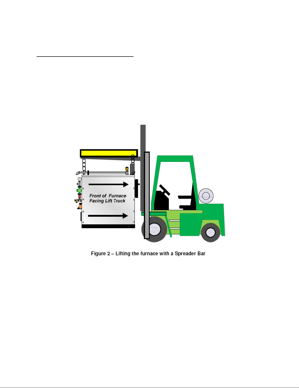
Method 2: Lifting the furnace from the top
Spreader Bar:
The WinterGreen furnace comes with 2 (two) lifting eyelets located on opposing top corners of the unit.
One method of lifting the unit can be the use of a spreader bar. The spreader bar can have either lifting
slings or chains. Place the bar diagonally across the forks of the lift truck and attach the chains or lifting
slings so as they are directly in line with eye hooks. (See figure 2) It is important that when the unit is
lifted there s no side pull on the eyelets as this will cause damage to the unit and possible personal injury.
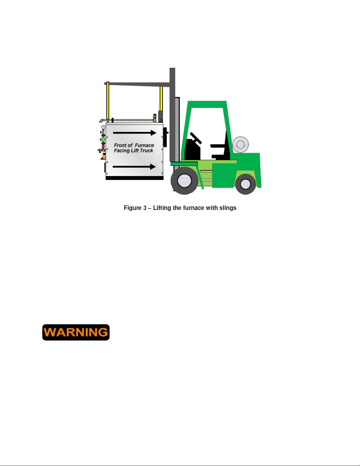
Slings:
To use just nylon lifting slings to lift the furnace, first slide one end of the sling through an eyelet until
both end sare of equal length. Do the same with the other eyelet. Both slings should be equal in length.
Adjust both forks on the lift truck so the center of each fork is directly centered to each eyelet. Slide each
sling over a separate fork. One sling will be to the back of one fork and the other sling will be to front of
opposite fork. Slowly lift the forks until there is tension. Check to see if there is any side pull on the eyelets. Several re-adjustments may have to be made before the sling position is correct. (See figure 3) Be
sure not to lift if there is any side pull, damage to the furnace will occur.
Continued on next page…
FURNACE – UNLOADING & MOVING Continued:
Note: The furnace should be placed on a non-combustible floor made of concrete or masonry. Consid-
eration should be made when deciding a location for the furnace, it should be close to a chimney, a
power source and have easy accessibility to your wood supply. If your WinterGreen furnace is to be lo-
cated in a garage, National Codes require that the lowest point of ignition be at least 46cm/18” from the
floor. If the furnace is to be installed in a separate enclosed space where combustion air is taken from
outside the garage, this rule does not apply.(See Page 17 – Mounting on a Cement or Masonry Base)
Although Your WinterGreen furnace is certified for minimal clearance from combustible surfaces, it is
advisable to verify local authorities for all clearances before the installation begins.
READ THE SECTION “FURNACE INSTALLATION –LOCATION” in the Owner’s Manual.
The installation location must have provisions to shelter the furnace from weather and protect it
from freezing intake air.
DO NOT INSTALL THIS FURNACE IN A MOBILE HOME OR TRAILER.
INSTALL A CARBON MONOXIDE DETECTOR AND SMOKE ALARM IF
THE NSTALLATION IS IN A HOME, GARAGE OR AN ENCLOSED AREA.
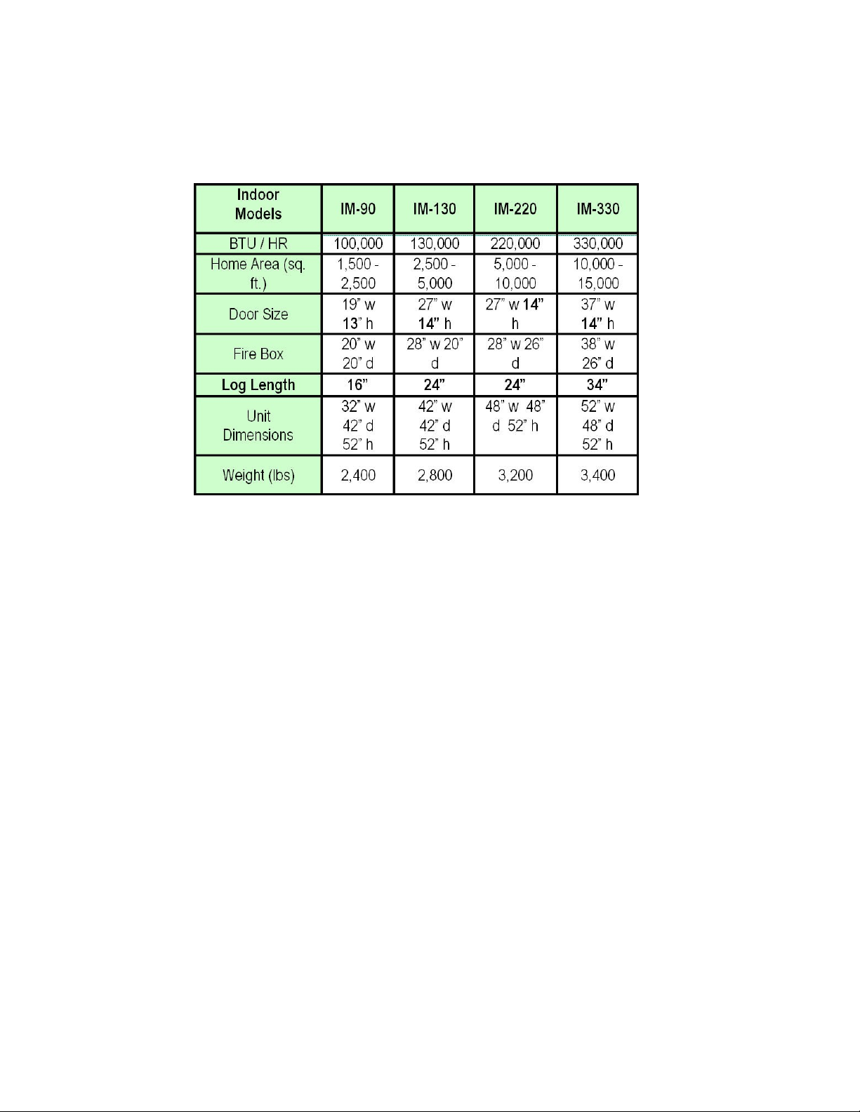
FURNACE - SPECIFICATIONS
General Furnace Specifications:
Note that many factors must be considered to determine “Heating Capacity” including the de-
sign of your home, how well your home is built, construction quality, insulation properties, climate in your area and what type of wood you are burning.
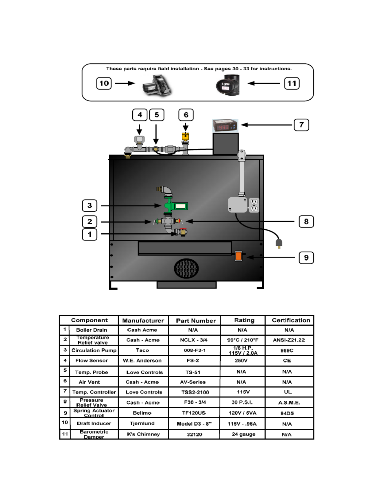
FURNACE – COMPONENT LIST
FURNACE INSTALLATION - LOCATION
It is very important to adhere to the installation clearances and restrictions stated in this
manual.
WinterGreen Furnaces are certified to be installed in most indoor applications, garage, and basements or out buildings that are sheltered.
DO NOT INSTALL FURNACE INSIDE A MOBILE HOME OR TRAILER! The furnace must be installed outside in a suitable sheltered building such as a shed or garage and pipe the hot water into
the mobile home.
The clearances provided are minimum dimensions determined by the manufacturer’s testing facility.
Installation of this furnace must comply with either the following Canadian or U.S. applicable regulations:
Installation is to be in accordance with National Fire Protection Association installation standards 90, 211, 70 (National Electrical Code) and Uniform Mechanical Code 913, 6-4 in applicable
states. Check with local building and fire code officials for regulations required for your area.
Provisions should be made for accessible power for the furnace.( See: ”Furnace Wiring” section )
WARNING: Wood storage must be kept a minimum of 1.5m (5 ft) from the furnace.
BEFORE installing the WinterGreen Furnace as an “add on to any existing installation, a thorough in-
spection and approval must be made of the existing systems by a qualified inspector. Any additional procedures shown in the installation instructions provided with the unit must be followed.
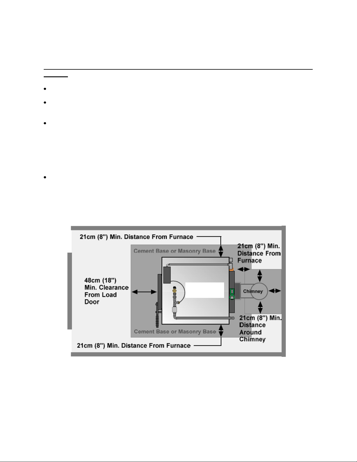
Top View
The WinterGreen Furnace must be installed on a solid concrete floor or 3 ½” thick masonry base.
See the above diagram showing minimum distance requirements that the floor must extend past
the furnace, flue and chimney pipe. DO NOT INSTALL THE WINTERGREEN FURNACE ON A
COMBUSTIBLE FLOOR
Cement or Masonry Base Clearances for the WinterGreen Furnace
Continued on next page…
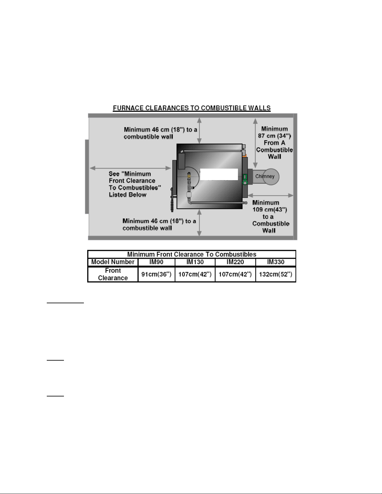
FURNACE INSTALLATION – LOCATION Continued:
When installing your WinterGreen Furnace it is important to adhere to the clearance dimensions
to combustible surfaces as shown below. Note that these are minimum clearances and your furnace should never be located any closer than the dimensions stated.
Top View
IMPORTANT:
The installation of this furnace must comply with the latest edition of NFPA 211 for Reduced
Clearances and/or your local building codes, whichever minimum clearances are greater.
Installation should be made by a qualified heating equipment installer (one who is engaged and
is responsible for, or is thoroughly familiar with the installation and operation of gas, oil and
solid fuel burning appliances; who is experienced in this type of work and familiar with all the
building code requirements and/or fire codes of the authority having local jurisdiction.)
NOTE: Any connections to an existing ductwork system of a forced air heating system must
comply with NFPA 90B, 2-1.1 and have plenums constructed of metal in accordance with NFPA
90B, 2-1.3. Contact your local H.V.A.C. professional for determining compatibility of the
WinterGreen Furnace to your existing heating system prior to installation.
NOTE: The furnace should be placed on a non-combustible floor made of concrete or masonry.
Consideration should be made when deciding a location for the furnace; it should be close to a
chimney, a power source and have easy accessibility to your wood supply. If your WinterGreen
furnace is to be located in a garage, National Codes require that the lowest point of ignition be at
least 18” from the floor. If the furnace is to be installed in a separate enclosed space where com-
bustion air is taken from outside the garage, this rule does not apply.

CHIMNEY - INSTALLATION
IMPORTANT: The following chimney instructions are for reference and guideline purposes only.
Chimney installation should be performed by a qualified chimney installer.
Be sure to read, understand and adhere to the installation clearances and restrictions stated in
this manual.
Masonry Chimneys: The use of an existing masonry chimney should only be considered if it has been
thoroughly inspected and approved for use with this furnace. The chimney must conform to State or National Building Codes. Consult local building code and fire code authorities for the proper requirements
in your area.
NOTE: WinterGreen does not recommend using a masonry chimney.
Factory Built Chimneys: New factory built chimneys must conform to type HT (High Temperature) re-
quirements of UL-103 for factory built chimneys and comply with the requirements of Chapter 11 of
NFPA 211 Standard for Chimneys, Fireplaces, Vents and Solid Fuel-Burning Appliances. Consult local
building code and fire code authorities for the proper requirements in your area.
Never connect to an aluminum Type B gas vent. As this is not approved
for the WinterGreen Furnace and is dangerous.
DO NOT USE A CHIMNEY CAP!
Do not connect furnace to a chimney flue serving any other appliance.
DO NOT SIDE VENT A SOLID WOOD BURNING FURNACE
Stove Pipe: The stove pipe and elbows used to connect from the WinterGreen Furnace to either a fac-
tory chimney or a masonry chimney must be black, heavy wall (24 gauge) thickness with a melting point
of not less than 2000˚F and conform to UL Standard S641 for flue pipes.
IMPORTANT: The flue connection between the furnace and chimney cannot have more than a
combined total of 180˚ in elbow connectors. (Example: 2 x 90˚ elbows or 1 x 90˚ and 2 x 45˚ el-
bows) The maximum straight length of flue pipe is 3 m (10 ft.) total and have an upwards slope
toward the chimney of 1/4” per foot to allow condensation to drain towards the furnace. All connections must have at least 1 3/16” overlap and a minimum of 3 fastening screws to prevent
separation. Provisions must be for visual inspection and cleaning either by cleanouts in the fluepipe or by removal of the flue pipe. Longitudinal seams of the pipe are to be located on the underside in horizontal runs.
Continued on next page… 19
CHIMNEY – INSTALLATION Continued:
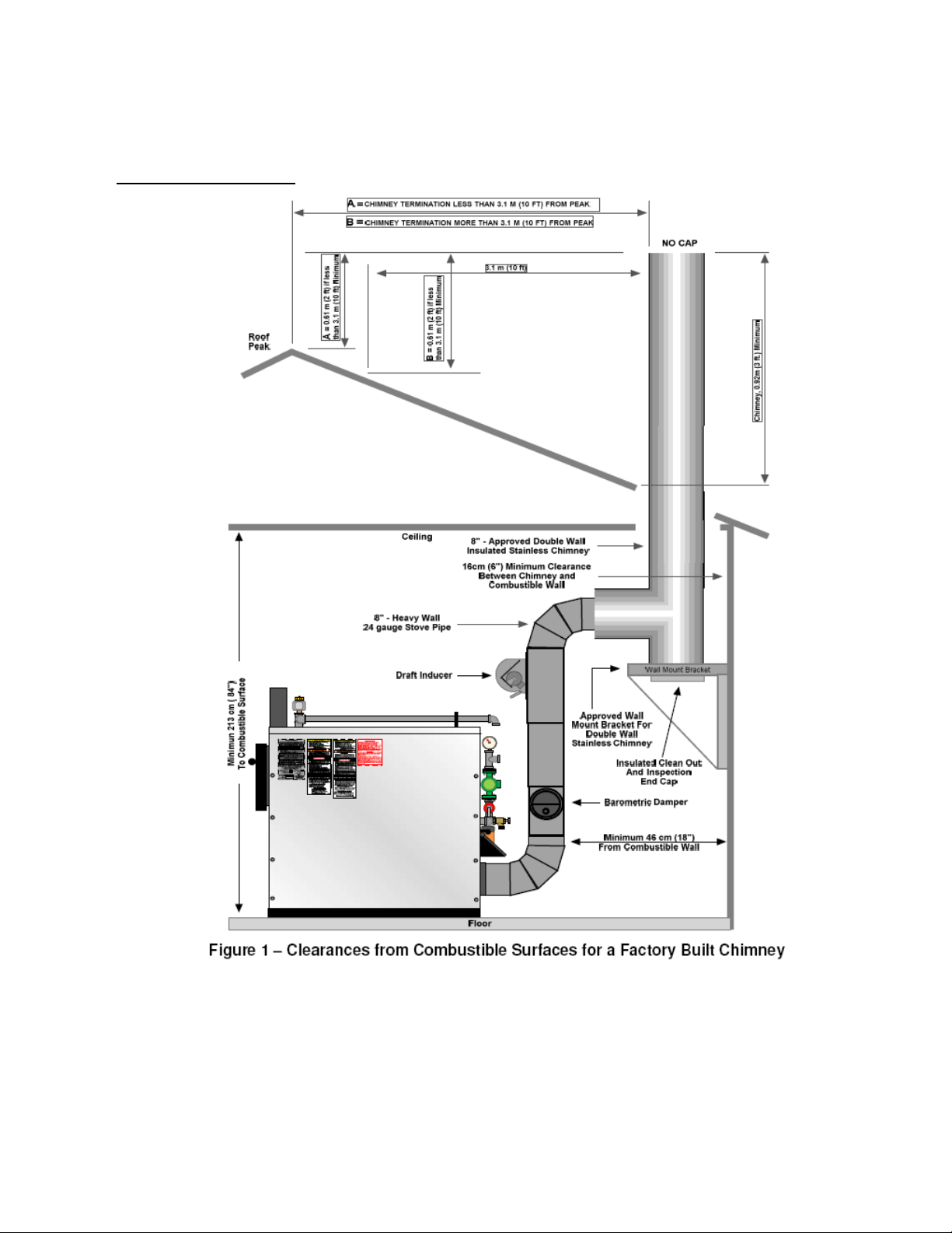
Factory Built Chimneys:
Note: The top of the chimney must extend at least 0.9 m (3 ft) above the highest point where it exits the
roof and be at least 0.6 m (2 ft) higher than any other point of the roof within 3.1 m (10 ft).
For draft proper operation, the chimney should be at least 3.6 m (12 ft) to 4.6 (15 ft) in tall.
When installing the new chimney, observe all building code requirements. Be sure to carefully
follow all the manufacturers installation instructions supplied with your chimney.
Continued on next page…
 Loading...