

Page 1

Installation Guide
for WA500-SU
Installation Guide
A Resource Guide for
Installation and Configuration
W i n T e l e c o m I N C.
Page 2

International Headquarters Address
143-1, SangDaeWonDong, JoongWonGu, SeongNamSi, GyeongGiDo,
South Korea
T E L: +82-31-744-0631
FAX: +82-31-744-0649
E-mail: [email protected]
Web site:
www.wintelecom.com.
WinTelecom makes no warranties with respect to this documentation and disclaims any implied
warranties of merchantability, quality, or fitness for any particular purpose. The information in this
document is subject to change without notice. WinTelecom reserves the right to make revisions to
this publication without obligation to notify any person or entity of any such changes.
Limited Warranty WinTelecom Inc. (“WinTelecom”) makes the following limited warranty. This
limited warranty extends to the original consumer purchaser and to no other purchaser or transferee.
Limited One (1) Year Parts and Labor Warranty for WinTelecom CPE Unit. WinTelecom warrants
this product and its parts against defects in materials and/or workmanship for a period of one (1)
year after the date of original retail purchase.
During this period, WinTelecom will repair or replace a defective product or part without charge to
you
Warranty Conditions
The above LIMITED WARRANTY is subject to the following conditions:
1. Warranty extends only to products distributed by WinTelecom.
2. Warranty extends only to defects in materials and/or workmanship as limited above.
Warranty extends only to defects which occur during normal use and do not extend to
damage to products or parts which results from alternation, repair, modification, faulty
installation or service by anyone other than an Authorized WinTelecom Service Center;
damage to products or parts caused by accident, abuse, or misuse, or maintenance,
mishandling, misapplication, or use in violation of instructions furnished by us; damage
which occurs in shipment or any damage caused by acts of God, such as lightening or line
surges.
3. You must retain your bill of sale or provide other proof of purchase.
4. Any replacement parts furnished at no cost to the purchaser in fulfillment of this warranty
are warranted only for the unexpired portion of the original warranty.
-1-
Page 3
CAUTION: Exposure to Radio Frequency Radiation.
Antenna shall be mounted in such a manner to minimize the potential for human
contact during normal operation. The antenna should not be contacted during
operation to avoid the possibility of exceeding the FCC radio frequency exposure
limit and the antenna used for this device must be installed to provide a separation
distance of at least 40 cm from all persons and must not be collocated or operating
in conjunction with any other antenna or transmitter. Also only specific approved
antenna shall be used with this device.
Page 4

Table of Contents
Introduction
Chapter1
Physical Intallation
Chapter2
Network Setup Wizard
Chapter3
Security Configuration
-2-
Page 5

C
ongratulation! As the proud owner of the state-of-the-art Wintelecom™
WA500-SU
MetroLink series wireless bridges have been designed to provide transparent,
high-speed data communications between two to 16 locations. Point-to-point,
multipoint, and repeater functionality are built into all WinTelecom wireless
Bridge fast and affordable broadband wireless access products.
This solution offers fast, reliable wireless connectivity with considerable cost
savings compared to wired alternatives. Utilizing proprietary 5 GHz
technology, the Metrolink bridge can easily replace an Ethernet or or
seamlessly integrate into a newer 100 Mbps Ethernet Local Area Network
(LAN).
Thank you for choosing Ascend Airlink and, by all means, enjoy your wide
area wireless networking device!!
-3-
Page 6
Physical Installation
The WinTelecom Products has Out Door Unit (ODU), AC/DC Power Adapter and
Console cable.
Before installation the hardware devices, customer have to preparing below items
for easy installation.
No
Items
1 LAN Cable between ODU and Switch / Hub
FTP Cat5e UV Protection or UTP Cat 5e
(Cable Length: Depend on customer environment)
2 RJ-45 Modular plug
3 RJ-45 Crimpter
4 LAN Cable Tester
5 Adjustable Spanner for fixing the ODU with Pole
6 Plus(+) type of screwdriver
-4-
Page 7
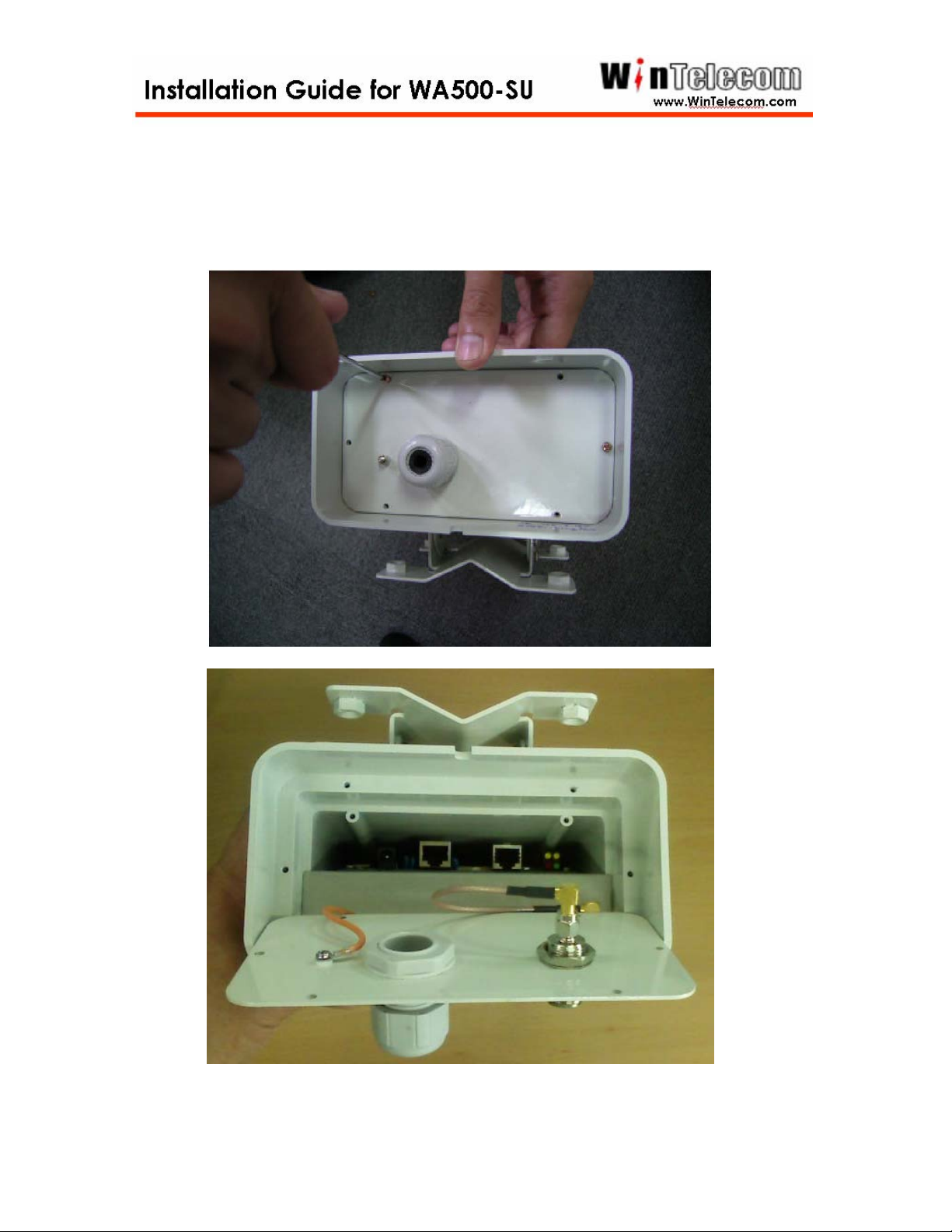
Step 1
Open the WA500-SU bottom case using plus screwdriver.
-5-
Page 8
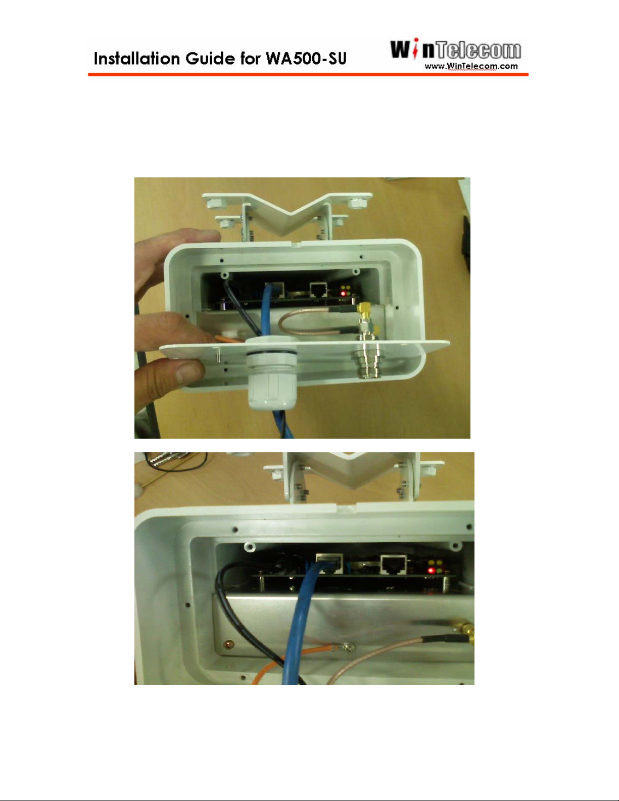
Step 2
Insert the Ethernet cable, DC Power Adapter through the waterproof
enclosure and then plug the Ethernet port In WA500-SU
-6-
Page 9
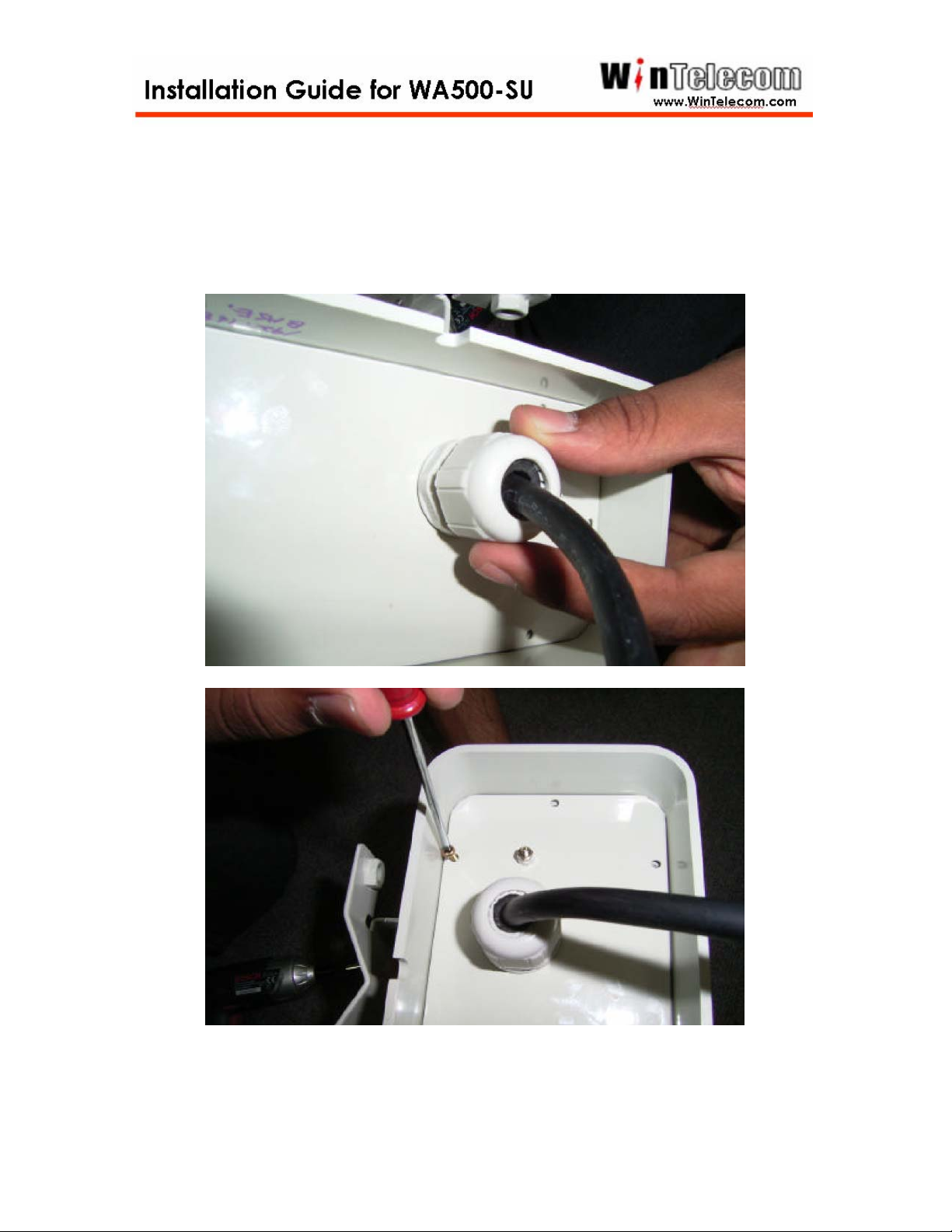
Step 3
Close the WA500-SU bottom case and then tight waterproof
enclosure.
-7-
Page 10
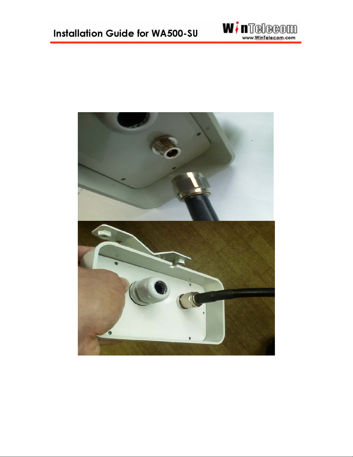
If You use the External Antenna. The Antenna cable connects with a
WA500-SU N-type Connector.
The antenna(s) used for this transmitter must be installed to provide a
separation distance of at least 40 cm from all persons and must not be collocated
or operating in conjunction with any other antenna or transmitter.
-8-
Page 11
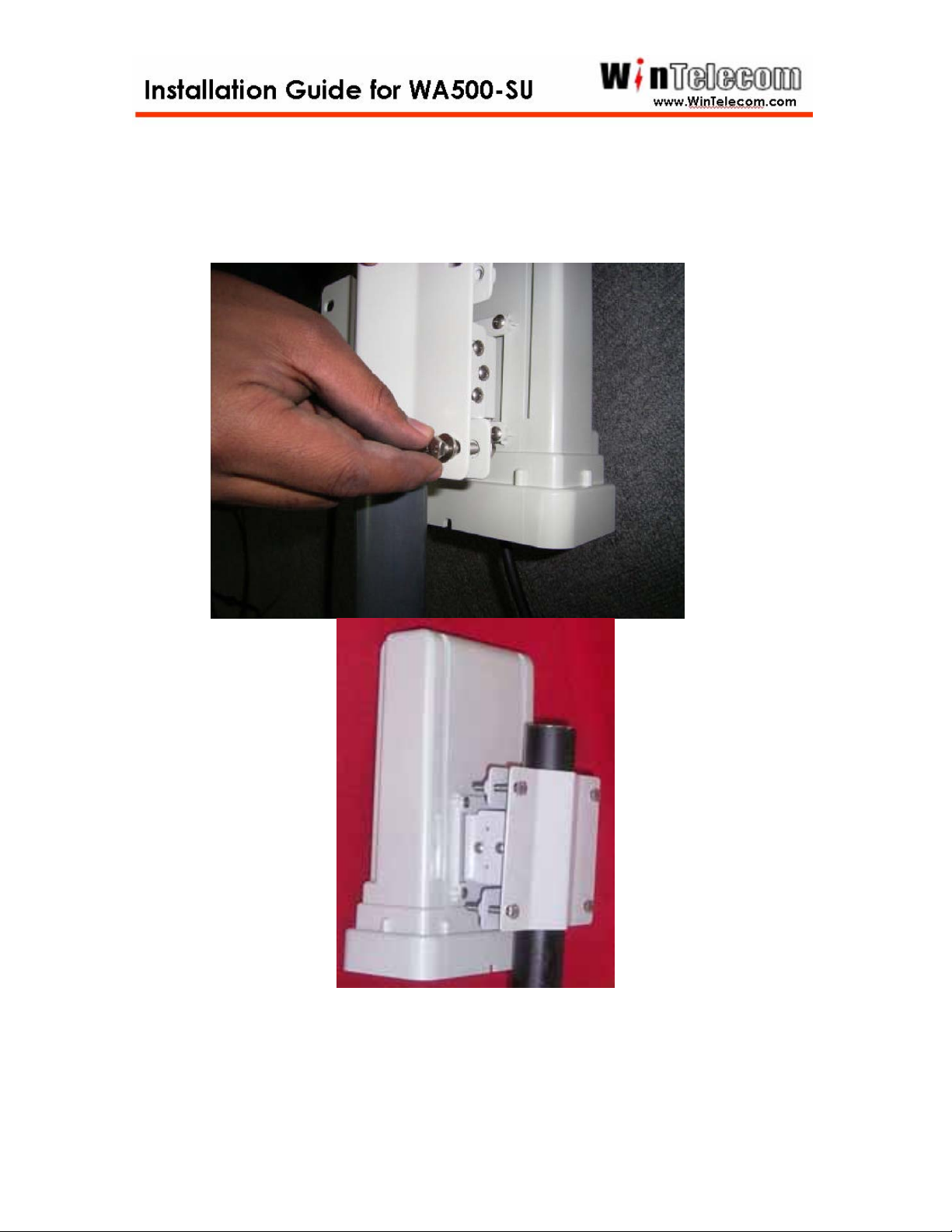
Step 4
A completion, WB500-SU with mounting kit should look like this.
-9-
Page 12
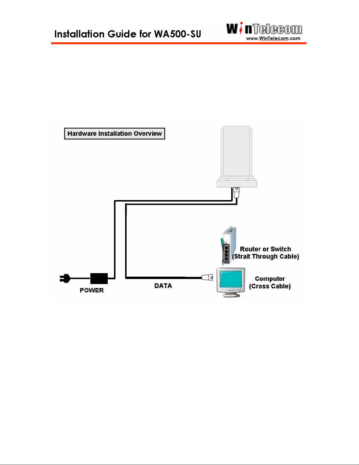
Step 5
Complete physical connection diagram.
-10-
Page 13
Network Setup Wizard
The WA500-SU is bridge mode Access Point devices.
The WA500-SU provides simple Plug and Play installation between wireless links.
When customer bought the WA500-SU, the Basic configuration was done by
manufacture. Customer just required physical installation.
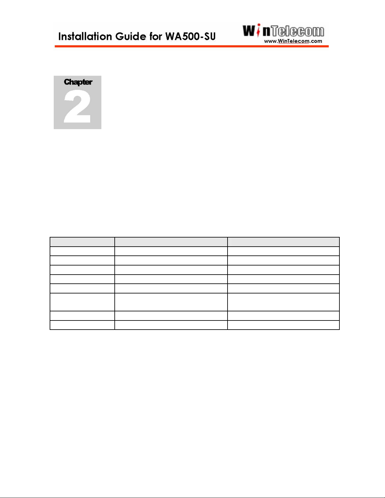
The table provides default value on the AP.
Value Base Station CPE
User ID win win
Password win win
System Name Base Station CPE
IP Address 192.168.1.70 192.168.1.71
Subnet Mask 255.255.255.0 255.255.255.0
Default Gateway
0.0.0.0 0.0.0.0
Address
SSID win70 win70
Frequency 5785MHz 5785MHz
If the user wants to change the configurations, the user Host PC IP address
has to change as below one of IP address.
-10-
Page 14
Plug & Play
If the user installed the systems with electricity power locally, the system
automatically working between links.
The WA500-SU provides Web based configuration.
Step 1
Launch a web browser. Netscape Navigator and Internet Explorer are examples of
commonly used web browsers.
Step 2
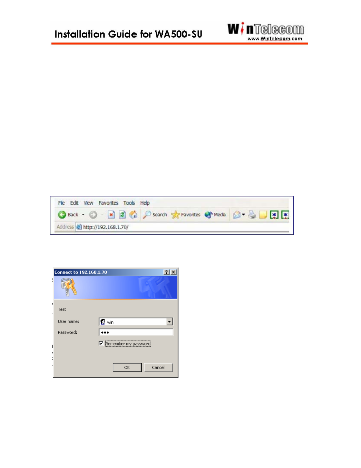
From the Host PC, enter the IP address that is assigned to the AP as the URL
address. For example, the default address is http://192.168.1.70. (The CPE default
IP address is http://192.168.1.71 )
The WinTelecom Metrolink bridge requires you to enter a user name and password
to gain access to the configuration utility.
The default User Name and Password is “WIN
”
Click OK to complete login process.
-11-
Page 15
Step 3
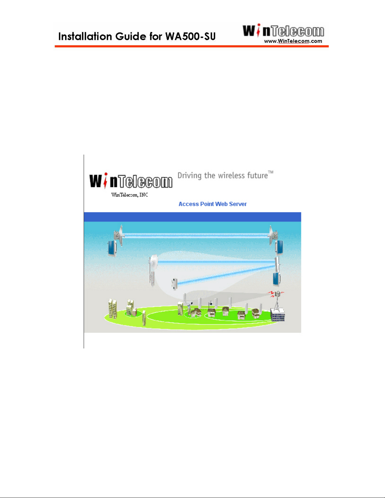
The AP Web server homepage appears.
Click on the image to access the configuration pages.
-12-
Page 16
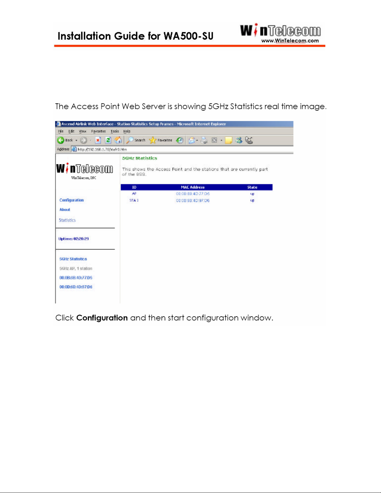
Step 4
-13-
Page 17
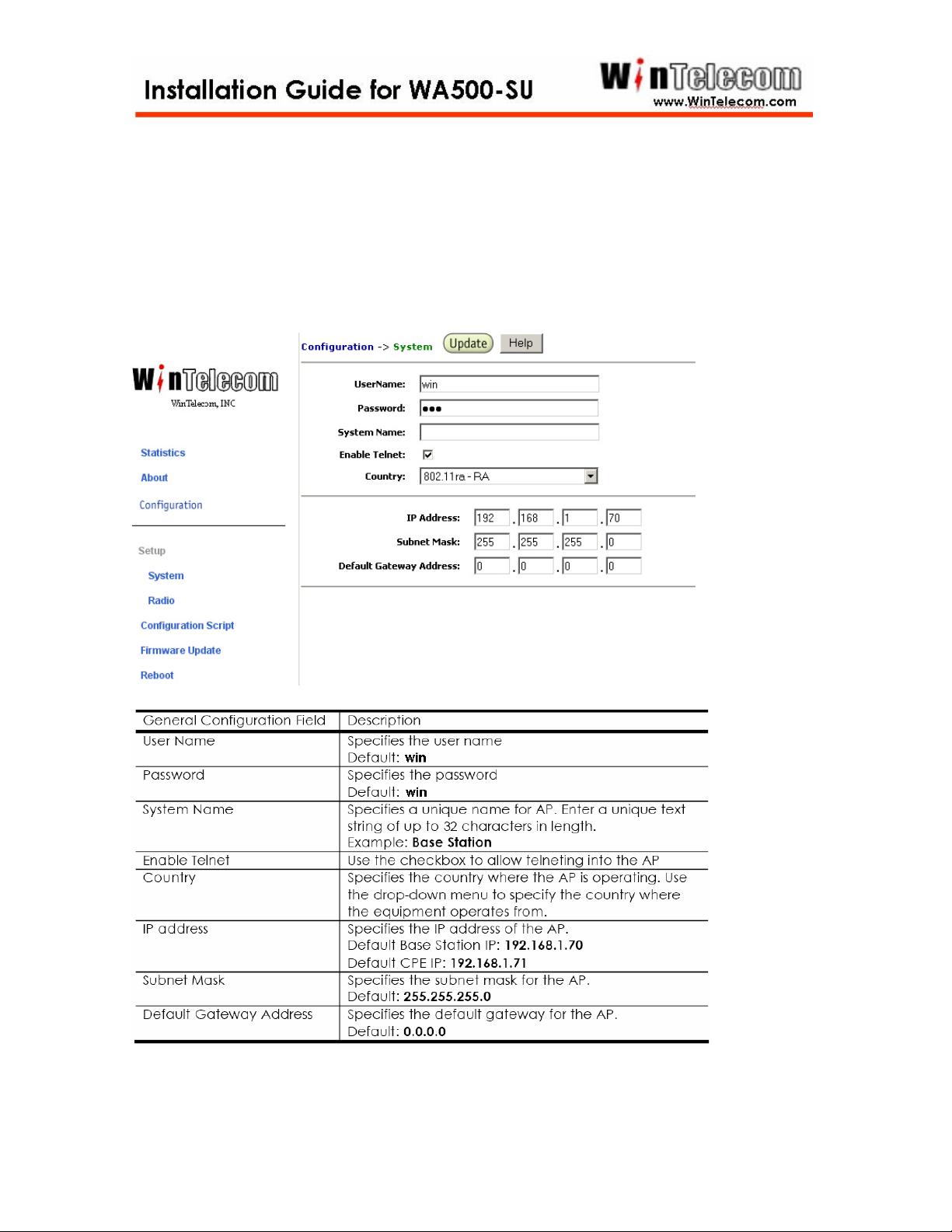
Step 5
The system configuration window allows the setting of general operating
information for the AP. Click on Configuration from any window to access the
system configuration window.
-14-
Page 18
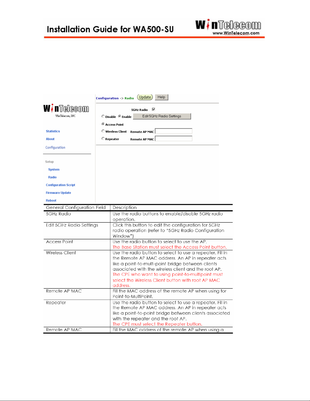
Step 6
The Radio configuration windows allow the setting of generic radio operating
Information for the AP. From the AP system configuration window. Click Rdio.
-15-
Page 19
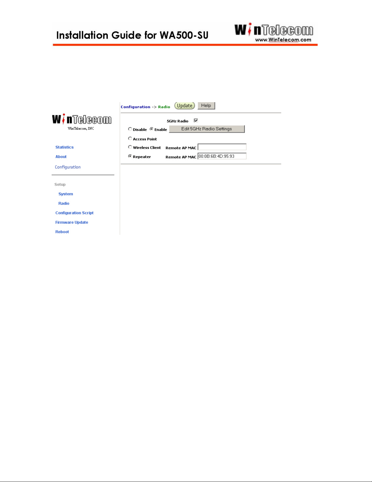
Below picture is showing CPE of POINT to POINT configuration.
The Mac Address of Remote AP Mac field is Bas Station Mac Address.
-16-
Page 20
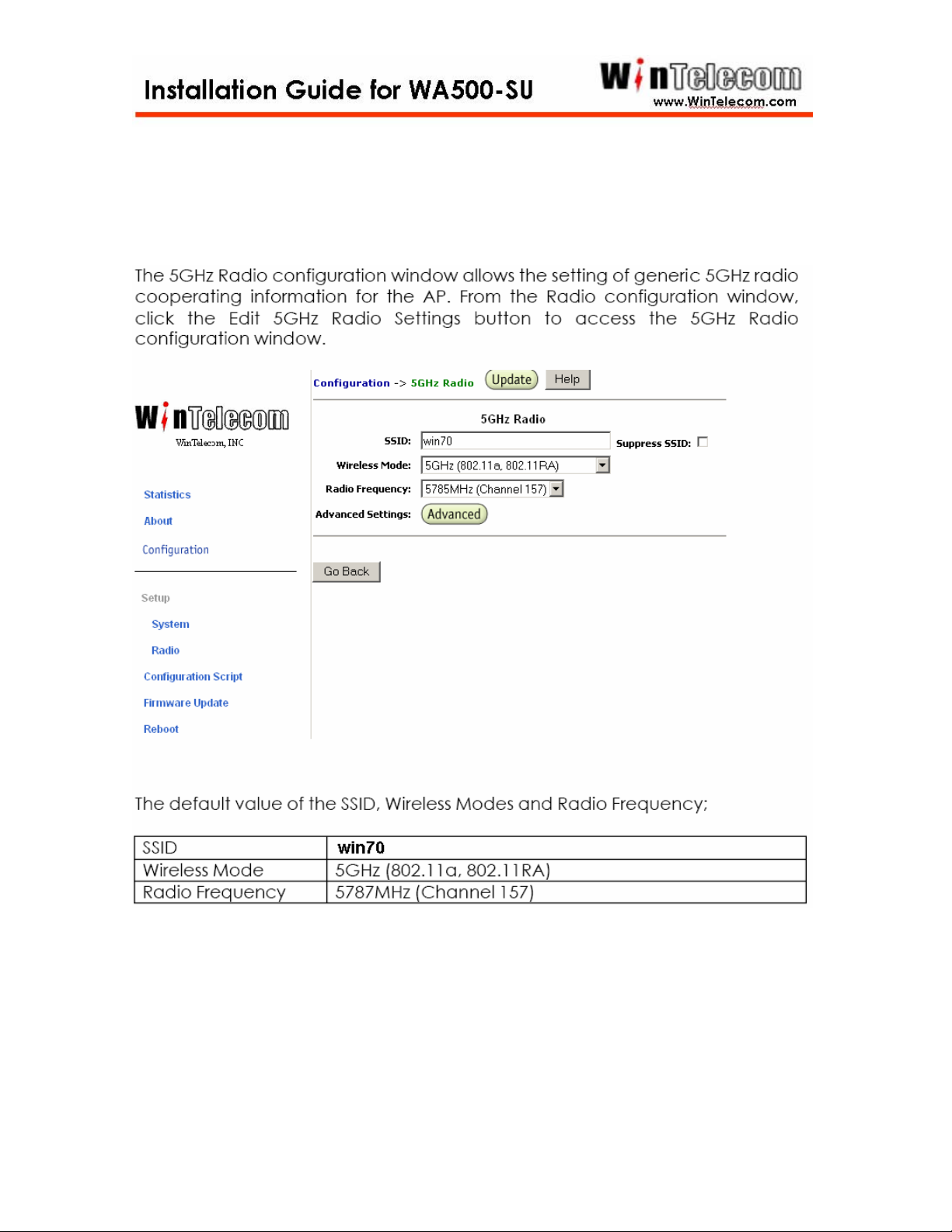
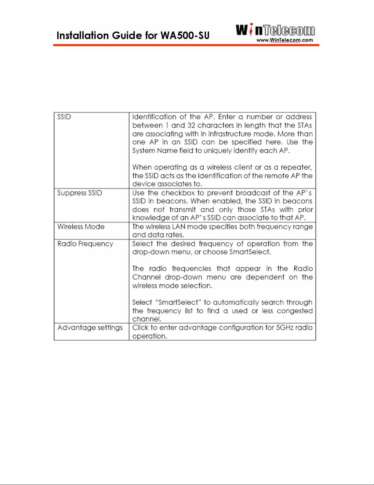
Step 7
-17-
Page 21
-18-
Page 22
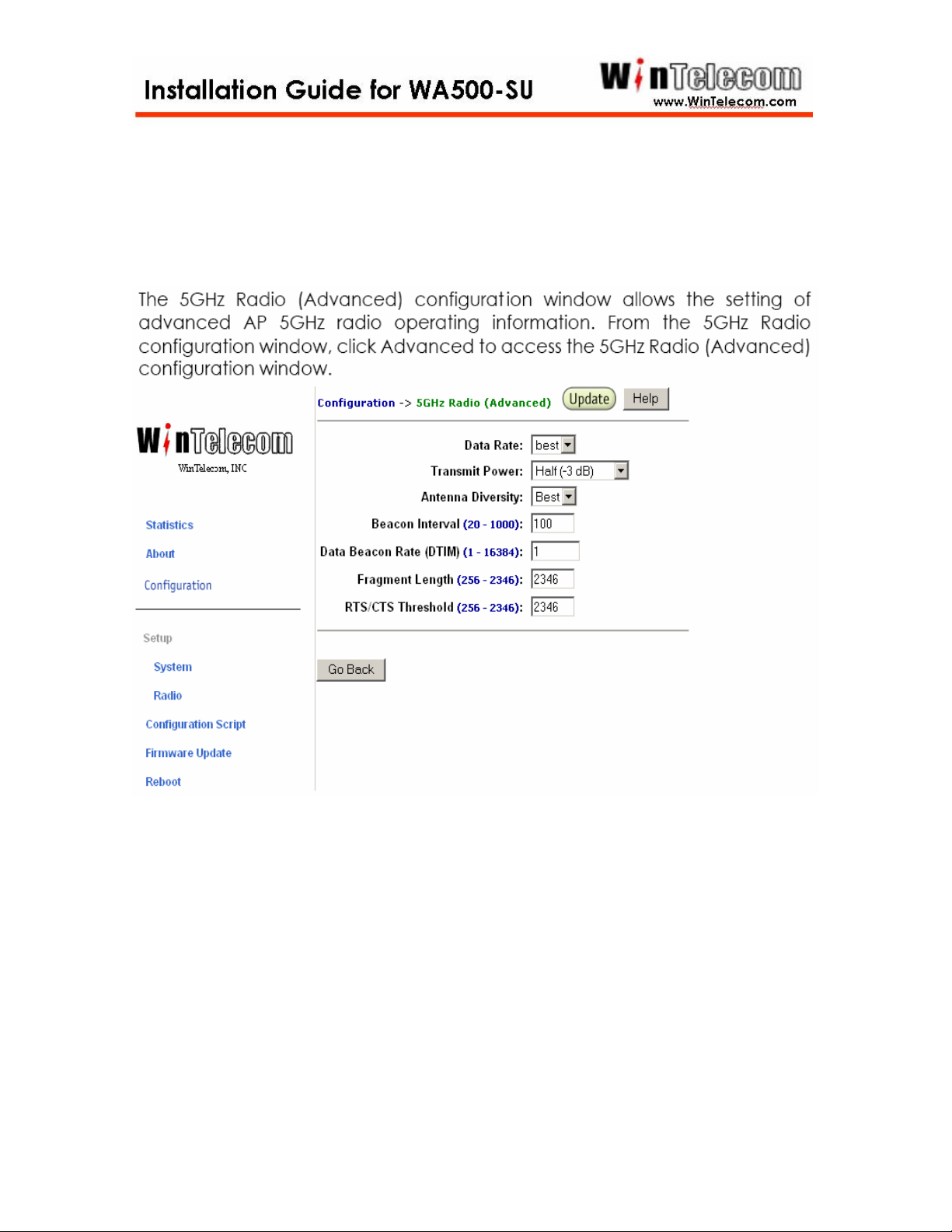
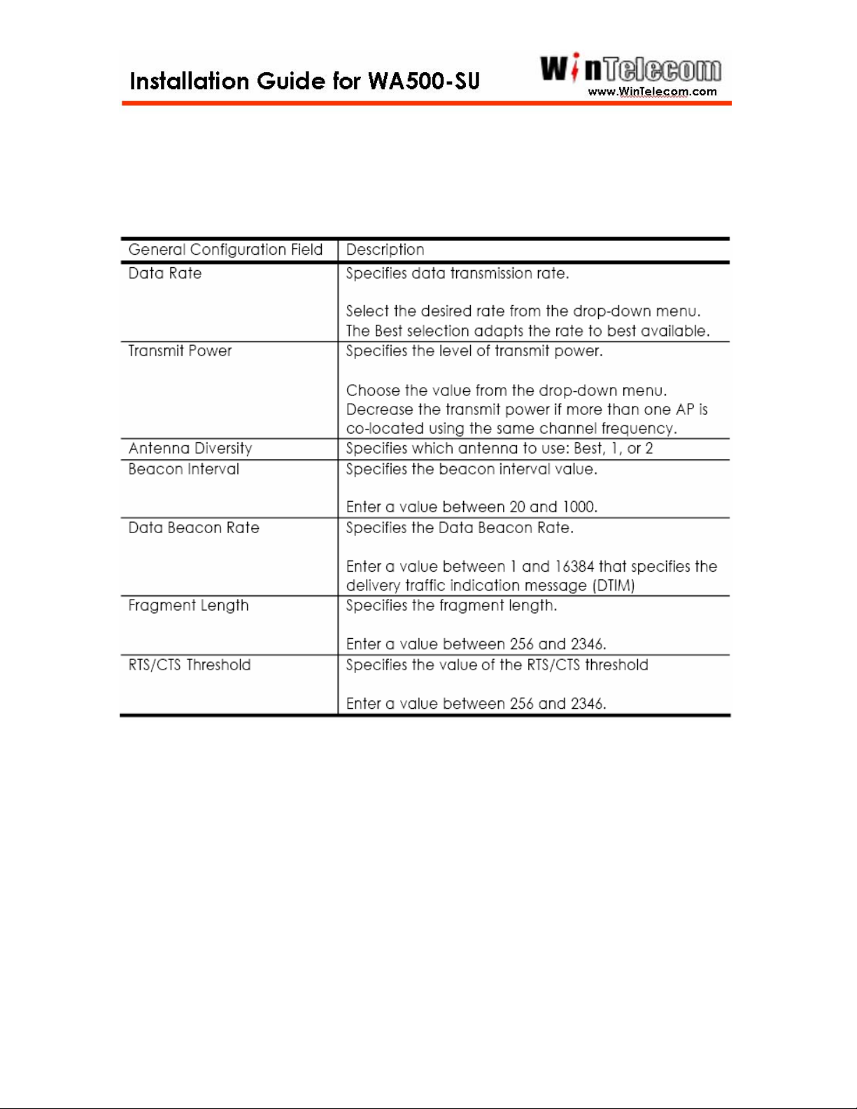
Step 8
-19-
Page 23
-20-
Page 24
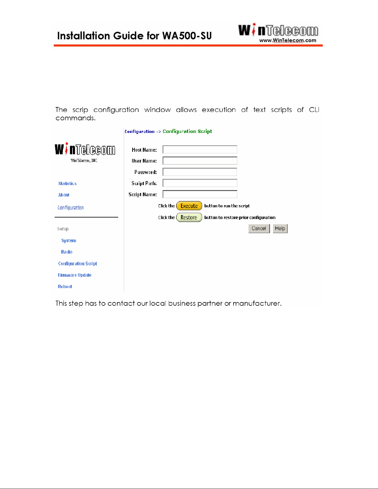
Step 9
-21-
Page 25
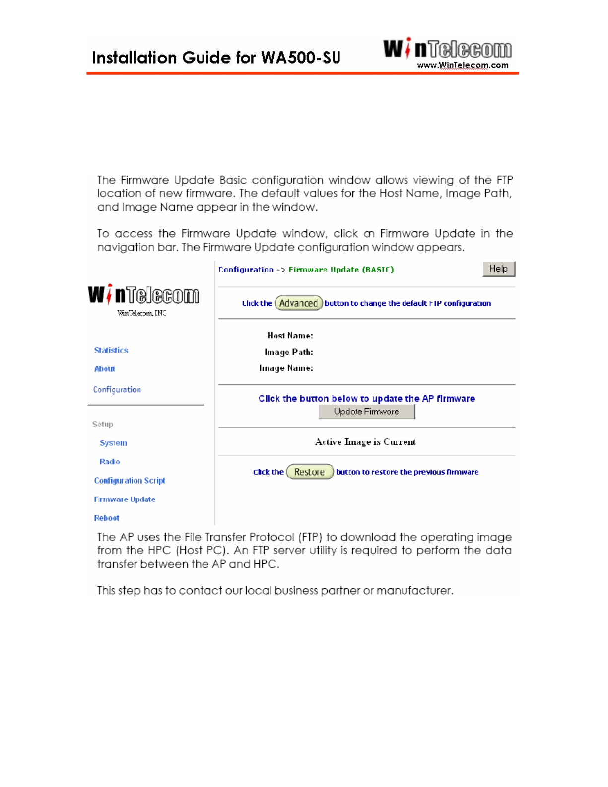
Step 10
-22-
Page 26
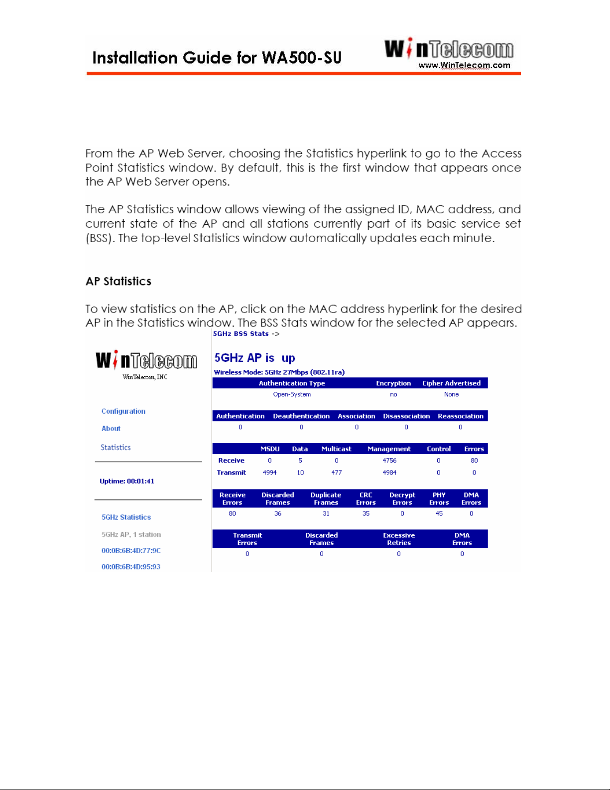
Step 11
-23-
Page 27
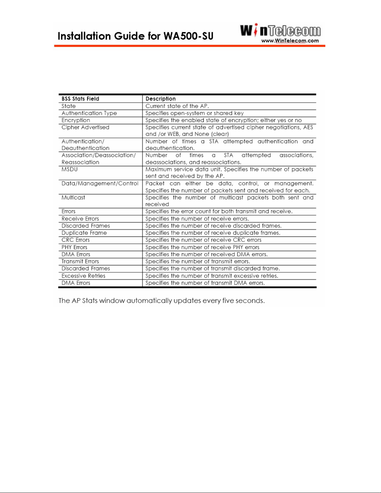
-24-
Page 28
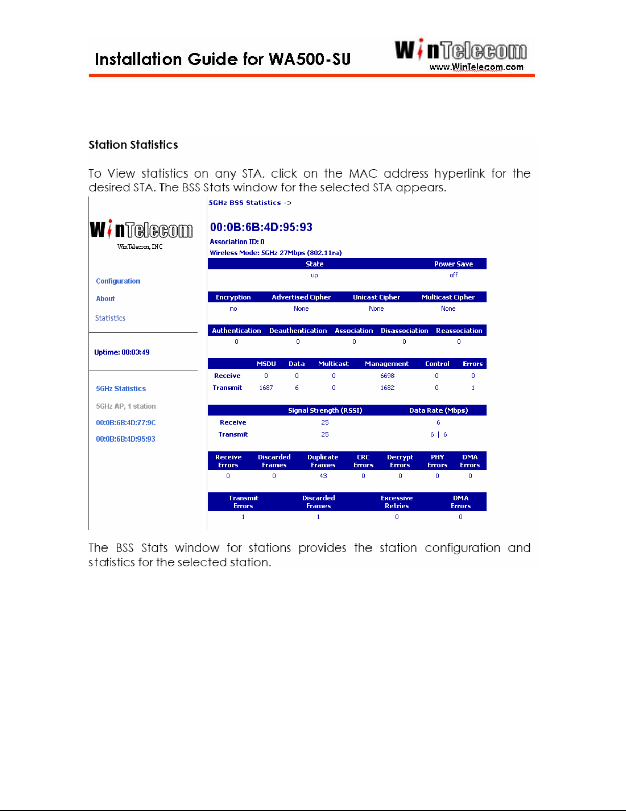
-25-
Page 29
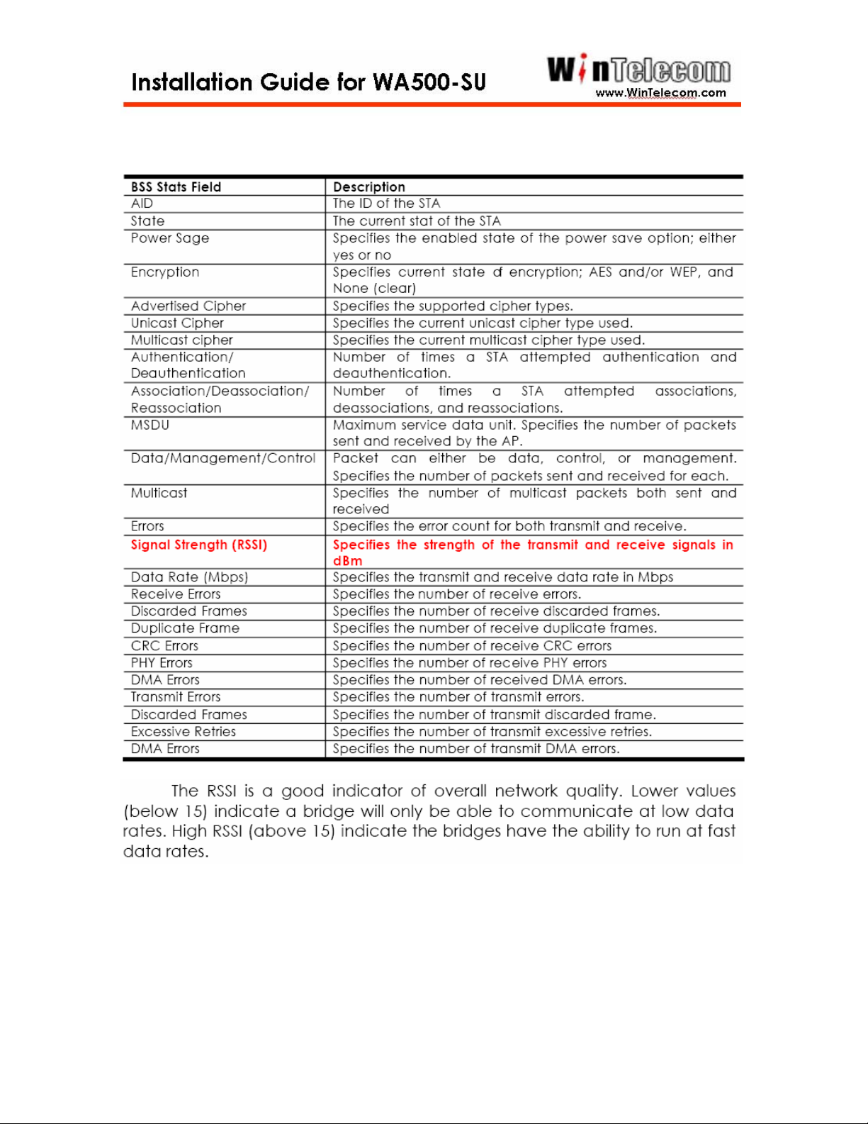
-26-
Page 30
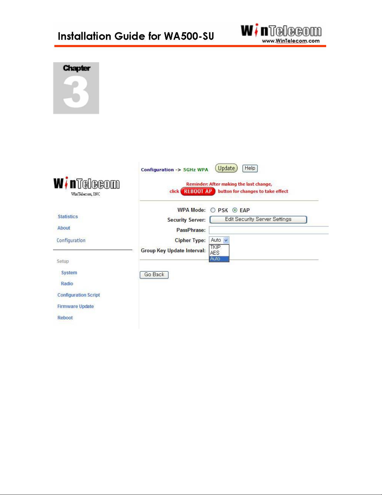
Security Configuration
Security Tab – Data Encryption
The Security screen provides links to the WinTelecom Metrolink List and Unique
Key Manager screens. It is also used to enter or update shared keys and data
encryption settings for the bridge. The following sections describe the entries of
each area on this screen.
-27-
Page 31

WinTelecom Metrolink Authentication
Click Configure to add, edit, or delete bridge MAC addresses from the WinTelecom
Metrolink authorization list.
Data Encryption
Encryption Type – WinTelecom Metrolink bridges support three types of
encryption. Default: Auto.
WEP – Wired Equivalent Privacy (WEP) data encryption (64, 128, or 152 bit
key lengths can be registered). The 64 bit keys must be entered as 10
hexadecimal digits in the range of 0-9, A-F, or a-f. If 128 bit is chosen, enter 26
hexadecimal digits. If 152 bit is chosen, enter 32 digits.
AES/WPA2 – Advanced Encryption Standard (AES) data encryption is the
most robust data encryption in the market today. It was designed to comply with
U.S. requirements [Federal Information Processing Standard (FIPS)] for use by
U.S. government organizations to protect sensitive, unclassified information. The
WinTelecom Metrolink supports 128 bit AES keys. Enter 26 hexadecimal digits.
TKIP – Temporal Key Integrity Protocol (TKIP) is a WPA security standard that
uses the original encryption key as a starting point to derive encryption keys
mathematically. TKIP automatically changes and rotates encryption keys so that
the same encryption key is never used twice. This is an automated encryption key
switching process that does not require user intervention.
Status – The status button indicates the current encryption state of your bridge.
Default: Disabled.
Disabled – No data encryption is enforced on your bridge.
Enabled – Data encryption is enforced on your bridge.
Key Update Interval – Specifies the group key update interval in seconds. The
value is only used with dynamic keys and can be either 0 (disabled) or any value
above 15. Default: 0.
-28-
Page 32

Security Server – For use with dynamic keys utilizing 802.1x security. Click on
Configure to set up the Security Server if dynamic (802.1x) encryption is selected
for the bridge on the security screen.
Follow these steps to enable Data Encryption on the bridge:
1. Select an Encryption Type (AES or WEP).
2. Change the Status to reflect the proper status.
3. Press Update to save settings.
4. Press Reboot to enable new security settings.
Encryption Key Manager
Pre-Shared Key Configuration – When you select Pre-Shared Key for encryption,
you should enter four default shared-keys in the Encryption Key Manager. Make
sure that each bridge in the network has an identical Key Entry Method, Encryption
Key, and Encryption Key Length.
Key Entry Method – You can use hexadecimal digits or ASCII text to enter each
key. Click on the "key length" drop-down menu to view lengths for each type of key.
Default Shared Key – Select the default pre-shared key you want to enable.
Encryption Key – Enter up to four pre-shared encryption keys.
Key Length – Specify the length of the pre-shared encryption keys.
Unique Key Configuration – When you select Unique Keys for encryption, refer
to the instructions below to enter keys. The bridge supports up to 60 unique keys in
the Unique Key Manager.
Use the following steps to add a Pre-Shared Key to the Key Manager on the main
security screen:
1. Select a Key Entry Method (hexadecimal or ASCII text).
2. Select a Default Shared Key.
3. Enter up to four shared Encryption Keys.
4. Specify the Encryption Key Length based on the Encryption Key just entered.
5. Press Update to save settings.
6. Press Reboot to enable new security settings.
-29-
Page 33
Follow these steps to add a Unique Key to the Key Manager:
1. Press Configure to open the Unique Key Manager screen.
2. Enter unique encryption keys.
3. Select the Key Size from the drop-down menu.
4. Enter the Key Value based on the Key Size selected.
5. Press Add New to add the key to the Key Manager.
6. Check the Key List to ensure the key value and size were entered correctly.
7. Press Reboot to enable new key settings.
Follow these steps to remove a Unique Key from the Key Manager:
1. Press Configure to enter unique encryption keys.
2. Enter the Key Number to delete.
3. Press Delete to remove the key from the Key Manager.
4. Press Reboot to enable new key settings.
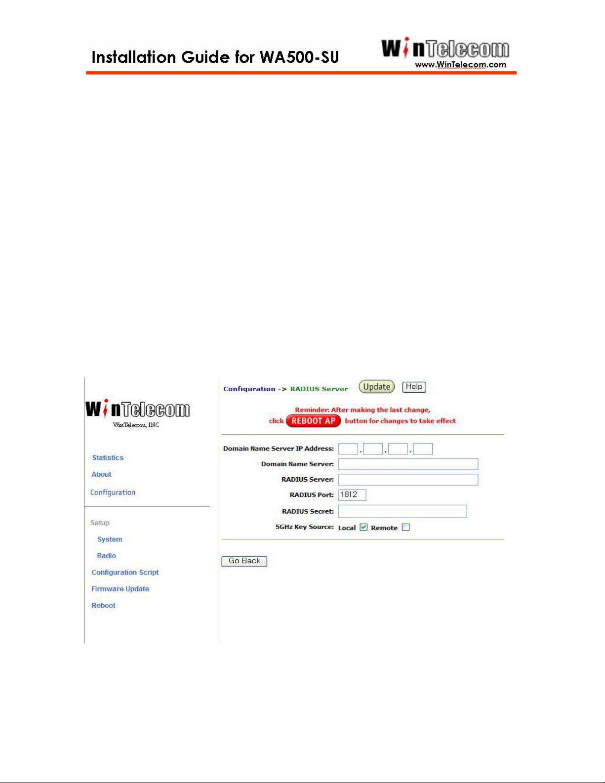
Security Server (RADIUS) Settings
This screen is used to view, add, and update a bridge’s security server settings. Note: This
feature is currently NOT implemented.
-30-
Page 34

This screen includes the following settings:
Domain Name Server IP Address – Specifies the IP address of the domain name
server.
Domain Name Server – Specifies the domain name server.
RADIUS Server – Specifies the IP address of the RADIUS server.
RADIUS Port – Specifies the port of the RADIUS server.
RADIUS Secret – Specifies the password for the RADIUS server.
RADIUS Key Source – Specifies the location of RADIUS keys.
5GHz Key Source – Check “Local” to specify that the keys are located in
the bridge; check “Remote” to indicate that the RADIUS keys are located on a
external RADIUS server.
-31-
 Loading...