

Page 1
MANUAL
Page 2

Thank you for purchasing Wintec products. Based on the innovative
technology in this ever-changing environment, we have developed
many wireless products that have attracted consumers’ attention. We
sincerely appreciate your interest in our products and we suggest you read
the instruction carefully. Your comment will be highly valued. Please read
through the manual in order to get familiar with the device and learn the
features of this model.
Safety Warning
Consumers need to have a clear understanding of the safe use of this
product.
Turn off power before fueling your vehicle.
Page 3

Contents
Controls and Switches …………………………………………………
Bluetooth Control Box Setting…………………………………………
LCD Icons ………………………………………………………………
Basic Operating Instructions …………………………………………
Setting Manual …………………………………………………………
CTCSS Code List ………………………………………………………
Systems Installation Diagram …………………………………………
Products Installation Diagram…………………………………………
Install The Antenna Mount……………………………………………
Helmet Headset Installation Diagram…………………………………
1
3
4
5
6
7
8
11
13
14
Install Boom Microphone ………………………………………………
Option Parts………………………………………………………………
Specifications ……………………………………………………………
15
16
18
Page 4
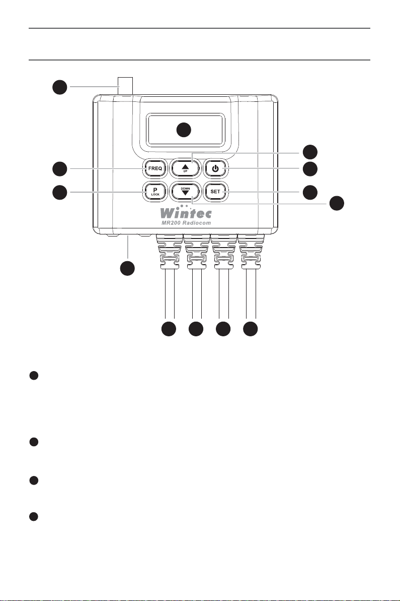
Controls and Switches
1
13
7
9
11
8
12
10
2
3 4 5 6
1
Antenna Jack (SMA Female)
The MR-200 is designed for use with antennas presenting an impedance of
near 50 Ohms at all operating frequencies. The antenna should be connected
whenever the transceiver is turned on.
2
USB Jack (Factory update)
Only for factory update.
3
AUX In
This connector provides AUX in for GPS, Navigation or other audio inputs.
4
Passengers Headset Connector
Passengers headset connector with PTT, Volume Control.
1
Page 5

5
Rider Headset Connector
Rider headset connector with Power ON / OFF, PTT, Volume Control.
6
Power In (DC12V)
DC Power in 12V
7
Freq / CH
Shows the current channel frequency.
8
P / Lock
Short press: Selector CTCSS code 1~51.
Press and hold:Key lock / unlock.
9
▲UP Key
Channel up and in settings mode is for selections.
10
DOWN Key
Channel down and in settings mode is for selections.
11
Backlight / Power
Short press: Backlight on / off
Press and hold: Power on / off
12
SET
Short press: Enter settings mode.
Press and hold: Exit settings mode.
13
LCD
Displays the current status of the MR-200.
8
9
2
Page 6
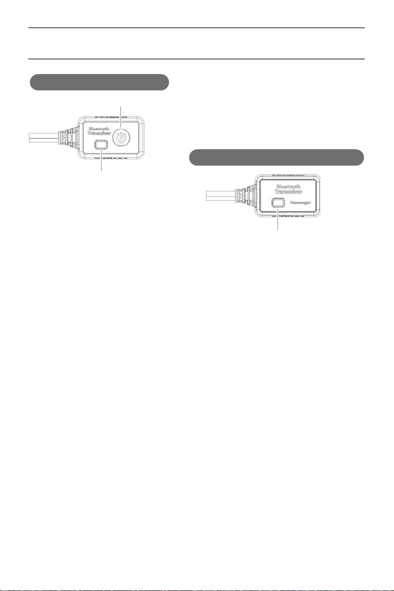
Bluetooth Control Box Setting
Rider BT(Bluetooth) Control Box Wire
Power ON / OFF
Passenger Rider BT(Bluetooth) Control Box Wire
Bluetooth function key / Status Indicator
Bluetooth function key / Status Indicator
Bluetooth Status Indicator
Waiting for connection: Blue light flashing.
Pairing mode: Red / Blue lights flashing.
Connected: Blue light stays on.
Power ON / OFF
Press and hold for about 3 seconds to for ON / OFF.
How to Pair Headset
Turn off the Bluetooth control box power (press and hold Bluetooth function
key about 3 seconds to turn off Bluetooth), Press and hold for about 6
seconds to go into pairing mode and the lights will be flashing Red / blue.
Clear All Paired Devices
Bluetooth control box can remember two paired headsets, if you need to clear
the pairing unit, with the blue light flashing (wait for link status), hold the
Bluetooth button about 12 seconds until the red light shows for 5 seconds,
then all pairings are cleared.
3
Page 7
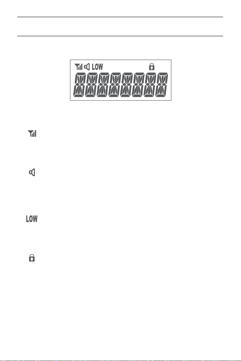
LCD Icons
Rssi / Tx Power Level
Shows the received or transmitted signal strength.
CTCSS
Indicates if the channels has been set with CTCSS or not.
Display of this icon indicates CTCSS is OFF.
Low Power
Indicates that the channel is set to low transmission power.
Key Lock
The Key lock is enabled when the icon is displayed.
4
Page 8

Basic Operating Instructions
Connect the MR-200 power cord to power the vehicle,
This will automatically turn on the MR-200 unit.
Turn On the Radio
Press and hold main unit or driver control box power buttons, then the
screen will light up and you will hear the startup tone.
Turn Off the Radio
Press and hold main unit or driver control box power buttons, there will be
a beep , LCD display will disappear and the system shuts down.
Adjust Chanel
Just press UP / DOWN to select the channel you need.
Adjust Volume
The MR-200 have two adjust the volume by driving / passenger control box
performs the driving / passenger to adjust the volume, the other is may also
enter the setting manual for volume adjust, please note the volume is too
large will damage your hearing.
* Oversized volume will likely cause irreversible hearing damage.
Transmit and Receive
Adjust the channel, press the PTT key driving / passengers control box
receiver / transmitter indicator will light up red, representing the current state
of transmitting radios.
Because there is a lot riding environmental wind shear sound and noise, so
the microphone close to your mouth as possible, and indeed aligned with the
front of the microphone mouth to get better call quality.
* Please observation of the driver / passenger control box / green light is on,
if so please don't pressing the PTT button to avoid the interference of others
communication.
Release the PTT button and radios will automatically return to the receiving
state waiting to receive.
5
Page 9
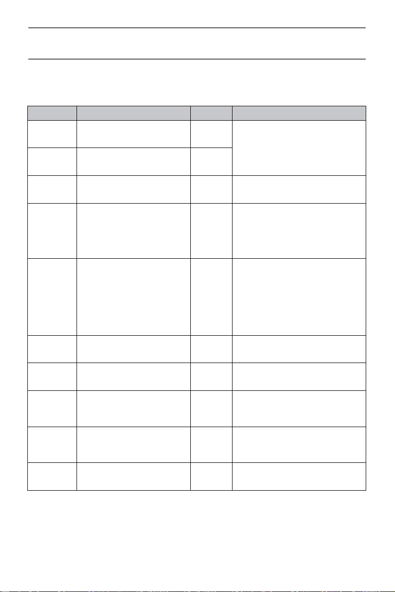
Setting Manual
Press SET key to enter settings mode, press SET again to advance
through the menu items. Press ▲▼ to adjust the settings.
Item Item Description Defaults Function Description
VOL 1 Driver volume adjust 5
0~9
VOL 2 Passenger volume adjust 5
DOUBLE Single or Double users Double Single or Double users
ON / OFF
RF
RF PRI Radio volume priority ON
Radio function
ON / OFF
ON
Turn on the radio function.
Turn off the radio function, just
only use intercom function.
Turn on this function when
radio signal with other signal
(GPS, Navigation...) come in,
then
adjust down other signal to
prioritise the radio signal.
will automatically
MR-200
SQL Squelch level setting Level 3 Level 0~ Level 7
SOUND Sound ON / OFF ON ON / OFF
APO Auto power OFF OFF
TOT Transmission Time-Out 90 sec
RESET Reset
to defaults NO NO / YES
MR-200
6
OFF
30 / 60 / 120 mins
OFF
30 / 60 / 90 / 180 / 360 sec
Page 10
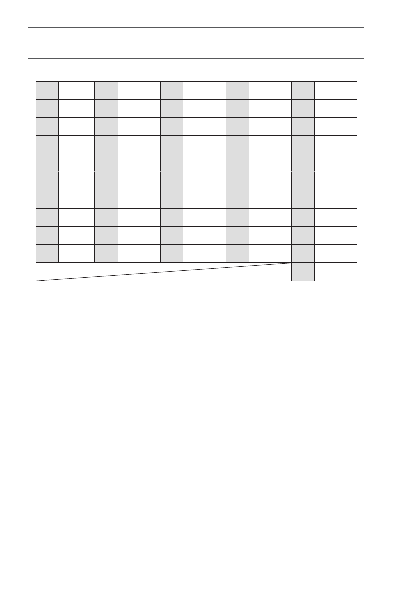
CTCSS Code List
1 67.0 11 97.4 21 136.5 31 192.8 41 159.8
2 71.9 12 100.0 22 141.3 32 203.5 42 165.5
3 74.4 13 103.5 23 146.2 33 210.7 43 171.3
4 77.0 14 107.2 24 151.4 34 218.1 44 177.3
5 79.7 15 110.9 25 156.7 35 225.7 45 183.5
6 82.5 16 114.8 26 162.2 36 233.6 46 189.9
7 85.4 17 118.8 27 167.9 37 241.8 47 196.6
8 88.5 18 123.0 28 173.8 38 250.3 48 199.5
9 91.5 19 127.3 29 179.9 39 69.3 49 206.5
10 94.8 20 131.8 30 186.2 40 62.5 50 229.1
51 254.1
7
Page 11
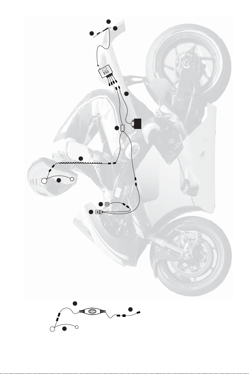
4
5
8
9
3
2
6
1
7
10
9
MR-200 Wired Version Systems
Installation Diagram
11
8
Page 12
T
a
sc
r
r
4
5
3
13
2
1
Transceiver
Bluetooth
12
4
14
eive
Passenger
n
luetooth
r
Bluetooth
Transceiver
1
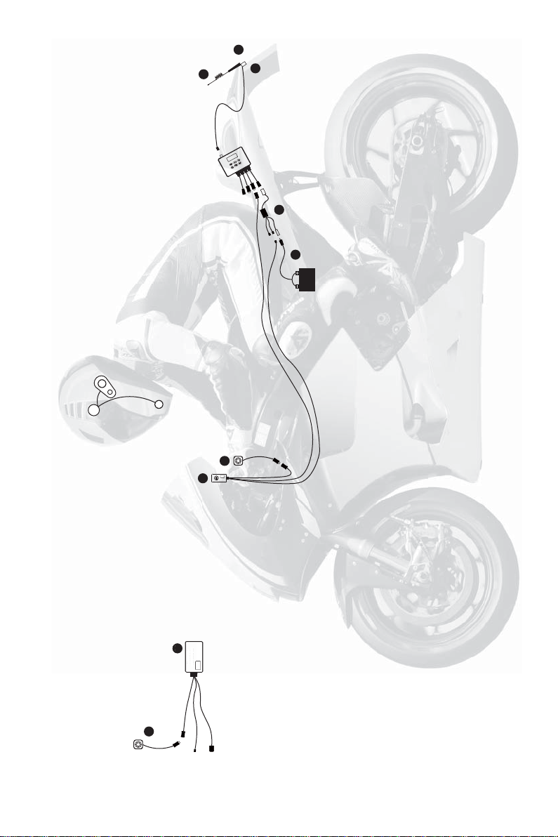
MR-200 Bluetooth Version Systems
Installation Diagram
9
Page 13
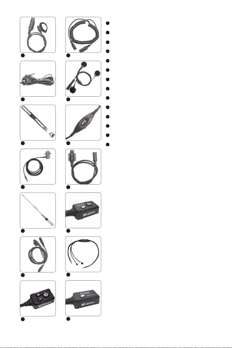
1 8
2 9
3 10
1
Rider PTT wire
2
Power wire
3
RF wire with connector (SMA-M)
4
Antenna mount
5
Antenna
6
Rider host wire
7
Rider control box wire
8
Rider helmets wire(QQ wire)
9
Helmet headset
10
Passenger control box wire
11
Passenger host wire
12
Rider BT(Bluetooth) control box wire
13
BT box power splitter
14
Passenger Rider BT(Bluetooth) control
box wire
4
5
6
7
11
12
13
14
10
Page 14
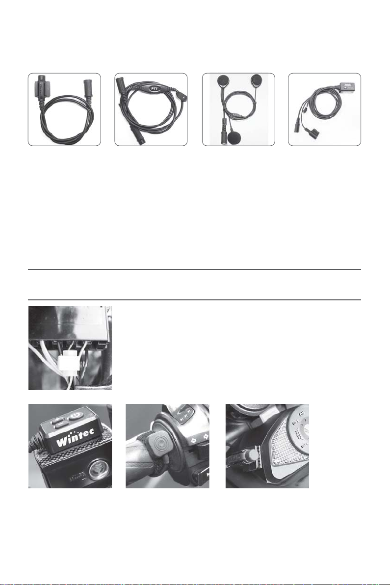
This product has a built-in Driver to Passenger intercom function, with optional
cable kit as below depending on whether you have a wired or Bluetooth
headset.
1
1
Passenger control box wire (Wired Version)
2
Passenger host wire (Wired Version)
3
Helmets headset (Wired Version)
4
Passenger Rider BT control box wire (Bluetooth)
234
* This product has A built-in external audio input with a 3.5mm Stereo socket.
Please use an original 3.5mm cable to avoid noise interference.
Products Installation Diagram
Power connection diagram
(+) Positive Ignition power supply or battery, etc.
(-) Negative.
★Rider control box wire ★Rider headset wireRider PTT wire
★ Wired Version
11
Page 15
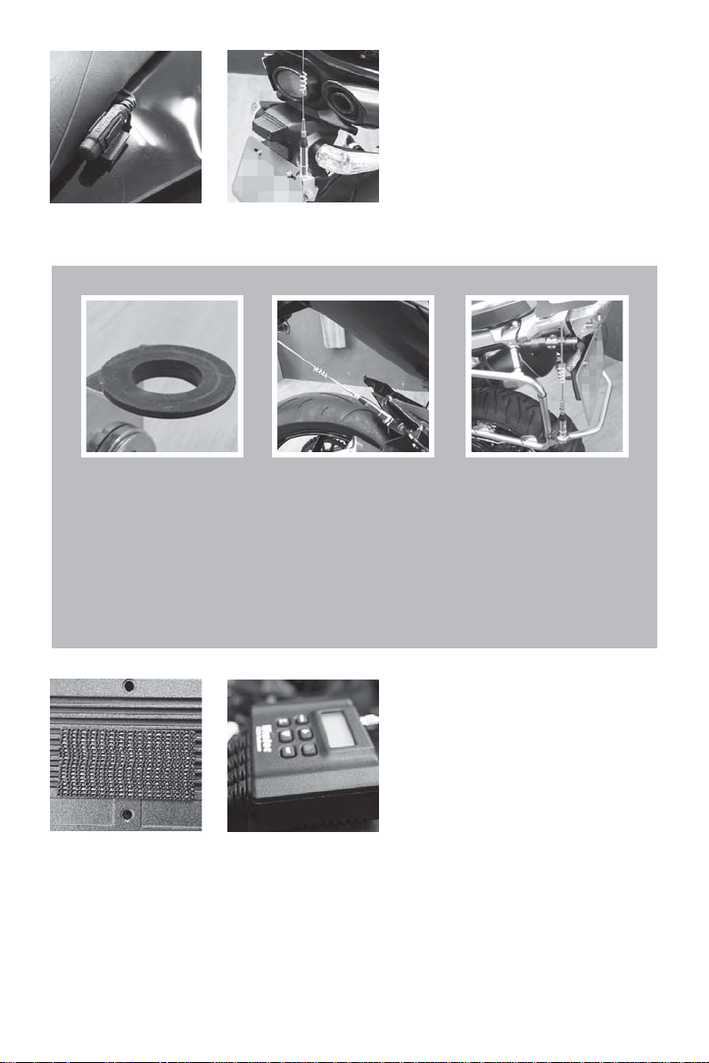
Install the antenna vertically
upright to give best performance.
★Passenger wire Antenna mount
installation diagram
Insulation of the Antenna
If users want to assemble the Antenna on the motorcycle
frame (Battery "-"), They need to place some insulated
rubber on the antenna mount in order to insulate from
electrical connection.
Use Velcro Tape to fix the radio
on to the bike.
12
Page 16
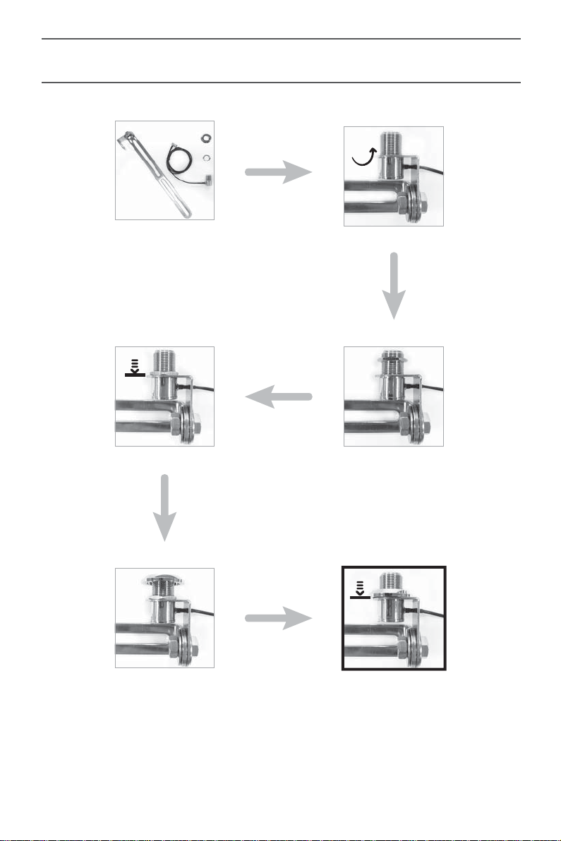
Install The Antenna Mount
4
2
3
3
1
2
1
3
4
13
4
Page 17
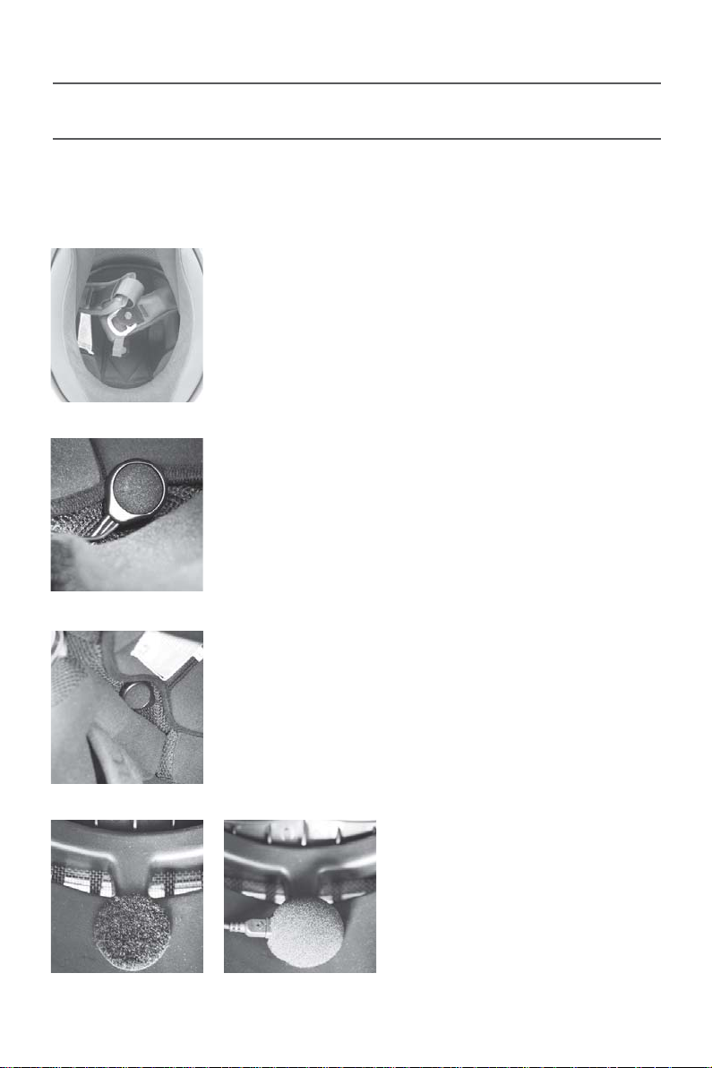
Wired Version
Helmet Headset Installation Diagram
IMPORTANT
Please insure the microphone is mounted to the front of the mouth to get a
better performance.
Please removable helmet lining.
Please make sure the LEFT speaker is positioned
exactly in line with your ear. If it is out of line you will
have limited performance.
Please make sure the RIGHT speaker is positioned
exactly in line with your ear. If it is out of line you will
have limited performance.
Set the microphone to a position
close to your mouth, a velcro tab
can be used to keep it in place.
14
Page 18
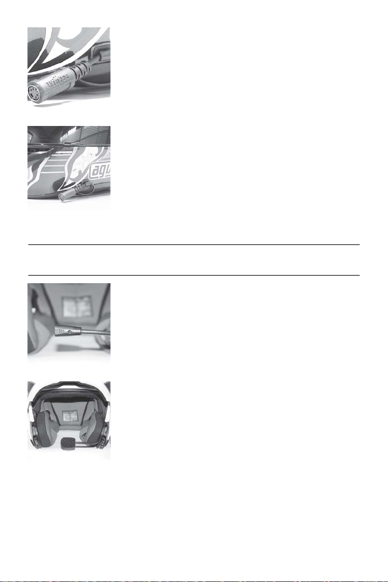
When using wired helmet headsets, please fix the
extension wire connectors to the outside of the helmet.
Install Boom Microphone
Keep the boom microphone fixed to the helmet, and
then adjust it to the front of your mouth.
IMPORTANT
Due to the directional microphone
used on these headsets, make sure the side with the
screw is facing away from your mouth.
15
Page 19
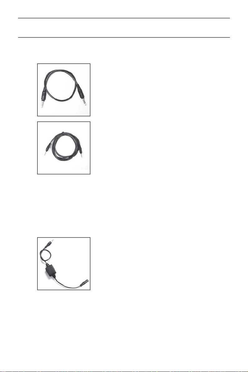
Option Parts
Dual Shielded Audio Cable
AUX-in for items such as radar speed detector, GPS and MP3.
Dual shielded audio cable 30cm
Dual shielded audio cable 200cm
Audio Input Filter
If using an external audio device powered from the vehicle, connected
to the MR-200 AUX-In, you may experience “Ground Loop” interference..
Users can use the “ Audio Input Filter “ to reduce the noise.
Audio input filter (one to one)
16
Page 20
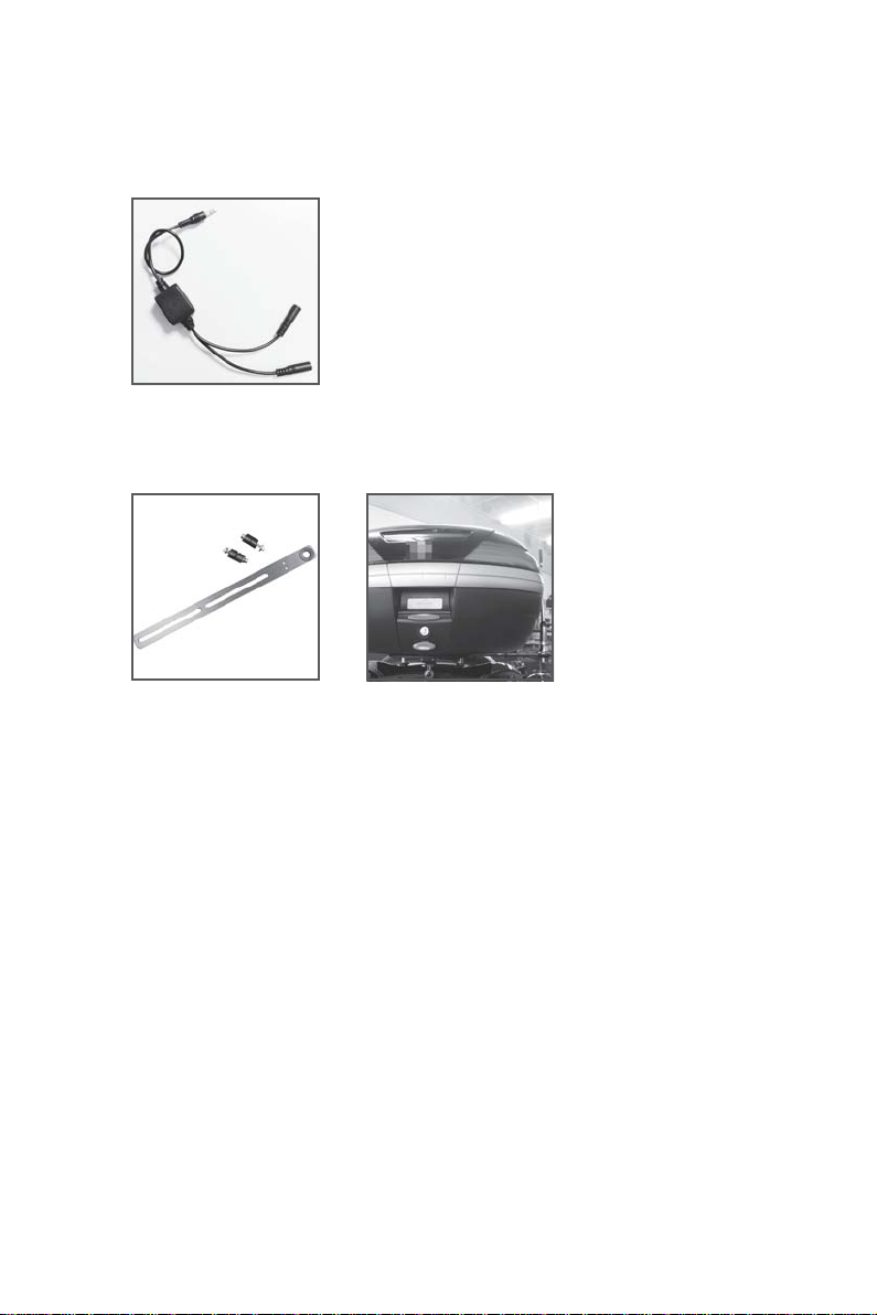
Two Audio Input Filter
If users want to connect two external audio devices to the MR-200 AUX-In ,
you can use the expanded “ Two Audio Input Filter “ . It can prevent
different voltage level issues causing problems.
Two audio input filter
Trunk Antenna Mount
17
Page 21

Specifications
General
Frequency Range
Channels
Sub-Audio
Modulation Type
Speaker Impedance
Operating Temperature
Weight
Size
Transmitter
RF Output Power
Current
Receiver
Receive Sensitivity
Receive Current
VHF 136~174MHz, UHF 400~520MHz
128
CTCSS / DCS
FM
16Ω 0.5W (Wired Headsets)
-30 ∼ +80
184g (Main body)
69(H)×80(W)×28(D) mm
500mW
Less than 500mA
Better than 0.2uV @ 12db SIAND
Less than 50mA
℃
Bluetooth
Size
Bluetooth Core Specifications
Frequency Range
Use Range
Operating Temperature
Power Source
33(H)x53(W)x19(D) mm
Bluetooth 2.1+EDR, Class II
2402 ∼ 2480GHz
10m
-10 ∼ +50
DC 12V
18
℃
Page 22

PK RI01-1 VER.2
 Loading...