

Page 1

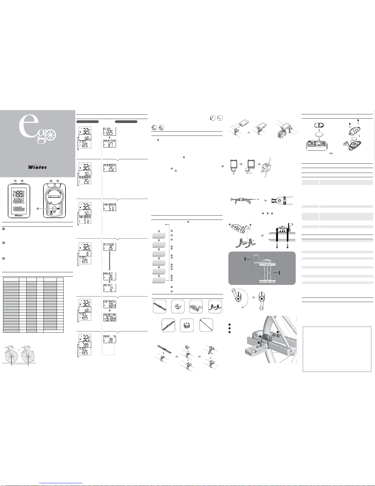
CLOCK
Display the time in 12-hours or 24-hours clock.
CADANCE The current RPM value. (0~199)
HEART RATE
Indicate the present heart rate value. (0~199)
MOVE TIME
Measure the time on riding from the reset on measured value since last
time. (00:00~99:99)
CADANCE The current RPM value. (0~199)
HEART RATE
Indicate the present heart rate value. (0~199)
GRADE(SLOPE)
Slope shows the percentage of the current value of the slope. Slope is
calculated by the change in height and distance, There might be
temporarily a slight discrepancy and delays occurred especially at low or
rapid change on speed. (-99~99)
CADANCE The current RPM value. (0~199)
HEART RATE
Indicate the present heart rate value. (0~199)
MAX. ALT
Measure the highest altitude from the latest reset on measured value.
(0~19999)
CADANCE The current RPM value. (0~199)
HEART RATE
Indicate the present heart rate value. (0~199)
TOT.ALT
Measure the grand total of ascent altitude from the latest reset on
measured value. (0~19999)
CADANCE The current RPM value. (0~199)
HEART RATE
Indicate the present heart rate value. (0~199)
DISTANCE
Measure the distance on riding since the reset on measured value last
time.(0~9999.99)
CADANCE The current RPM value. (0~199)
HEART RATE
Indicate the present heart rate value. (0~199)
ODOMETER
When resetting the odometer, the data won’t return to zero, you need to
change the value of it in the setting mode. (0~9999.99)
CADANCE The current RPM value. (0~199)
HEART RATE
Indicate the present heart rate value. (0~199)
TEMP
To indicate the present degree on temperature. (0~199)
CADANCE The current RPM value. (0~199)
HEART RATE
Indicate the present heart rate value. (0~199)
CALORIES
Measure the amount of calories consumption from the reset on measured
value since last time.(0~19999)
CADANCE The current RPM value. (0~199)
HEART RATE
Indicate the present heart rate value. (0~199)
Auto Scroll
The unit will scroll
and change to next
information page
automatically per 5
minutes.
AVG . SPEED
Measure average speed calculated from the total distance divided with
time on riding. (0~9999.9)
AVERAGE CADANCE
Record data on the value of average cadence from the last clearance on
the record.(0~199)
AVG. HEART RATE
Measure the average heart rate from the latest reset on measured value.
ALTITUDE
The indication on the present altitude. The present altitude is calculated
based on the barometer. Even at the same position, the altitude may
have a little discrepancy due to the different conditions on the weather.
Even when in a stable weather condition, the same position of altitude
may differ in 20 meters from daytime to nighttime. (-999~19999)
CADANCE The current RPM value. (0~199)
HEART RATE
Indicate the present heart rate value. (0~199)
MAX SPEED
Measure the fastest speed from the reset on measured value since last
time. (0~9999.9)
The FASTEST CADENCE
Record data on the value of fatest cadence from the last clearance on the
record.(0~199)
MAX. HEART RATE
Record data on the value of fatest cadence from the last clearance on the
record. (0~199)
A
B
C
Wheel Size (Reference Chart)
Overview
Operating the Unit
Setting Mode
Bike Info
Installing the Unit
Replacement of Battery
Maintenance
Specification
Trouble Shooting
Notice
A. B.
CR2032
+
Detection zone
5mm
5mm
Cadence
Magnet
Speed
Magnet
A B C
CR1632
+
0984
B
A
TTERY
CR 1632
MADE IN TAIWAN
2.4GHz ANT+ Wireless Bike Computer
Instruction Manual
PK CA01 VER.1
Design Patented
Press the button to switch and look through the cycling information on
information page.
In the setting mode, press the button to change numbers or measurement units.
When entering the altitude adjustment, press the button to switch among three
types of adjustment or the numbers.
Function key
Backlight / Heart Rate / Switch key
Setting Button
‧
‧
‧
On the information page, press the button can enable the backlight, and the
backlight stays on 5 seconds before turning off.
On the information page, press the button longer to turn the heart rate function
On or OFF.
In the setting mode, press the button to shift the selected parts on numbers or
units.
When entering the altitude adjustment, press the button to shift the selected
parts on the screen.
‧
‧
‧
‧
In the information status, press and hold the setting button on the back for 3
seconds to enter the setting mode.
In the setting mode, press the button shortly to scroll over the setting functions.
In the setting mode, press and hold the setting button on 3 seconds again to
return to the information page.
‧
‧
‧
Spin the wheel and choose one piece
of the spoke or let the valve stem
vertically straight to the ground to be
A point marked on the surface of
ground.
Then spin the wheel in one circle and
when the same piece of spoke or the
valve stem reaches to the ground
again, mark the position of it as B
point on the ground.
Measure the distance between point
A and B (mm) to acquire the wheel
size for setting.
Tire Size
L (mm)
Tire Size
L (mm)
Tire Size
L (mm)
27 x 1-1/4
27 x 1-3/8
650 x 35A
650 x 38A
650 x 38B
700 x 18C
700 x 19C
700 x 20C
700 x 23C
700 x 25C
700 x 28C
700 x 30C
700 x 32C
700C Tubular
700 x 35C
700 x 38C
700 x 40C
2161
2169
2090
2125
2105
2070
2080
2086
2096
2105
2136
2170
2155
2130
2168
2180
2200
12 x 1.75
14 x 1.5
14 x 1.75
16 x 1.5
16 x 1.75
18 x 1.5
18 x 1.75
20 x 1.75
20 x 1-3/8
22 x 1-3/8
22 x 1-1/2
24 x 1
24 x 3/4 Tubular
24 x 1-1/8
24 x 1-1/4
24 x 1.75
24 x 2.00
24 x 2.125
935
1020
1055
1185
1195
1340
1350
1515
1615
1770
1785
1753
1785
1795
1905
1890
1925
1965
26 x 7/8
26 x 1(59)
26 x 1(65)
26 x 1.25
26 x 1-1/8
26 x 1-3/8
26 x 1-1/2
26 x 1.40
26 x 1.50
26 x 1.75
26 x 1.95
26 x 2.00
26 x 2.10
26 x 2.125
26 x 2.35
26 x 3.00
27 x 1
27 x 1-1/8
1920
1913
1952
1953
1970
2068
2100
2005
2010
2023
2050
2055
2068
2070
2083
2170
2145
2155
A B
1.
2.
3.
Note: To measure accurate tire size, please refer to the following ways per
instructions.
The “up” arrow on the screen displays the present speed is higher than
the average speed. On the other hand, the “down” arrow on the screen
displays the present speed is lower than the average speed.
The “up” arrow on the screen displays the present heart rate
is higher than the average one. On the other hand, the “down” arrow on
the screen displays the present heart rate is lower than the average one.
The up symbol above the RPM indicates the current average rate is
higher than average rate of cadence. On the contrary, when the arrow is
facing down, the current average rate is lower than average rate of
cadence.
LCD contrast can be adjusted when the battery is installed on the unit. In the
meantime, all the icons will show up on the display by 3secs, in the meantine, press
function key(darker) or Backlight/Switch key(lighter) any of it to make adjustment .
If the setting is done, press setting Button to exist.
Press function key for 3 secs can clear the present data back to Zero execpt the
altitude adjustment. For the altitude adjustment, please refer to the operation of
Altitude adjustment Mode.
Data Reset
If the main unit does not receive a signal or when keypads or sensor do not triggered
after about 10 minutes, the main unit enters power saving mode and only displays
the time info.
Power Saving Mode
Under the power saving mode, press function key can wake up the information
page.
Auto Start / Stop
LCD Contrast Adjustment
The product supports ANT + speed and cadence sensor. If we need to re-pair it,
please enter the setting mode. Set the mode to the system in SC.SCAN to perform
the pairing. Since this product supports two bikes recording in A or B , you can select
one of it, and pair the speed and cadence sensor, the system will record the sensor
ID paired in A or B bike respectively, When you choose A or B mode, the system will
imported the related sensor ID automatically.
*Before performing the paring of speed/cadence sensor, please make sure the battery
has been installed and be sure to roll the magnet over the detection zone on the
sensor in advance in order to activate it successfully.
Speed/Cadence Sensor Pairing
To enable the heart rate sensor, please switch to the information page, press the
backlight/heart rate/switch key to enable or disable the heart rate sensor. (When there
is the icon “
” shown on the screen means the sensor is on, if the icon “
”
disappeared means the sensor is turned off.
If the unit cannot detect the value of heart rate for 1 min, it will close down the heart
rate function.
Enable the Heart Rate Sensor
The product supports ANT + heart rate sensor.
Please enter the setting mode. Set the mode in HR.SCAN to perform
the pairing process. Please make sure the battery has been installed in the sensor
and wearing on the right position before starting up the pairing progress.
Pairing the Heart Rate Sensor with Unit
Under the information browsing page, if any of it contains the altitude related info(like
MAX.ALT, TOT ALT, GRADE), in the meantime, press function key 1 for about 3 secs
to enter the altitude adjustment mode. After the setting is done, press the function key
for 3secs again to return to the informatin page.
There are three selections for altitude adjustment.
1
ADJUST: Adjust and input the altitude manually according to any operating
environment like riding along seacoast or mountain riding. The height can be acquired
on the positions.
2
Home: Adjust and input the altitude manually according to the default altitude at
home.
3
Default: Calculation on altitude according to the factory default.
Altitude Adjustment
Clock Setting
Setting on
Tire Size
KMH/ MPH
Setting
Odometer
Setting
A or B bike
Setting on
Age
Pairing on Heart
Rate Sensor
Speed/Cadence
Sensor Pairing
Press and hold the setting button on the back for 3 seconds
to enter the clock setting mode. Return to the information page,
press and hold the button for 3 seconds again.
Function key: Select time in 12-hours or 24-hours clock or
set the time in lower line.
Backlight/Heart Rate/Switch key: To shift the selected
parts between 12-hours or 24-hours clock or time setting.
Setting Button: Store the setting value and go to the next
selection for clock or time setting.
Clock Setting
Function key: Select the indication on KMH or MPH unit.
Setting Button: Store the setting value and go to the next
selection for tire size setting.
KMH / MPH Setting
Function key: Select the bike A or B.
Setting Button: Store the setting value and go to the next
selection for tire size setting.
A or B bike
Function key: Change the numbers of length.
Backlight/Heart Rate/Switch key: Shift the selected parts
on numbers.
Setting Button: Store the setting value and go to the next
selection for odometer setting.
Setting on Tire Size
Function key: Change the numbers of Age.
Backlight/Heart Rate/Switch key: Shift the selected parts
on numbers.
Setting Button: Store the setting value and go to the
nextselection for Odometer setting.
Setting on Age
Function key: Change the numbers of odometer.
Backlight/Heart Rate/Switch key: Shift the selected parts on
numbers.
Setting Button: Store the setting value and go to the next
selection for speed/cadence sensor pairing page.
Odometer Setting
Function key: Perform the pairing on speed sensor and return to the
information page
Setting Button: Go to the pairing on heart rate sensor setting page.
Speed/Cadence Sensor Pairing
Function key: perform the pairing on heart rate sensor and return to the
information page.
Setting Button: go to the clock setting page.
Pairing on Heart Rate Sensor
Enter / Return to the
information page,
press and hold the
button for 3 seconds.
Rubber Holder
Heart Rate Sensor MagnetCadence Magnet Strap
Bracket
Speed/Cadence
Sensor
Rubber Holder
for Speed Sensor
straps in normal size
How to Install the Bracket
Install the bike computer on the A. handle bar or B. stem
Install the Bike Computer
*Please make sure the unit has been well-clicked into the bracket.
Installing on Magnet of Speed Sensor
Please remove any dirty or oily things on the spoke to make sure no slipperiness
before installing magnet.
Release the safety hook on the magnet.
Be sure to clip it on the spoke tightly into the most inner side of gap on the central
of two-sided magnet.
Lock the safety hook back on magnet in order to avoid it being thrown off in cycling.
1.
2.
3.
4.
Installing Cadence Magnet
Please place the cadence magnet into silicone band.
Please penetrate the wider strap into the the silicone band to prevent the cadence
magnet fallen off.
Please measure and circle the silicone band on the crank to measure the most
proper in length and cut the extra unnecessary pars of band off by a scissor.
Finally, fix the position of silicone band by the strap.
1.
2.
3.
4.
Please clip the magnet for
speed sensor on the spoke,
place the spoke into the bottom
side of crack.
Installing on the Speed/Cadence Sensor
Assemble the rubber desk with sensor.
( → → )
Please parallel detection zone on the sensor to the central surface on magnet.
Measure the appropriate length of rubber desk when tie it up on the frame of bike
with the straps and cut the additional parts off.
1.
2.
3.
Wearing on the Heart Rate Sensor
1.
2.
3.
thin straps
1
Cadence Magnet
2
Speed/Cadence Sensor
3
Speed Magnet
1
2
3
No Display
(1) Check the battery capacities and it will be in low efficiency when in the cold
season.
(2) If the battery installed upside down?
(3) Make sure the battery case locked on the unit.
No Speed info
(1) Check if there are some dust inside the contacts on bracket or on the unit.
(2) Make sure the distances between sensors and magnet is within 5mm.
Not Correct Value on Speed and Distance
(1) Make sure the correct value setting on tire peripheral.
(2) Make sure the distances between sensors and magnet is within 5mm.
(3) Unload the battery and install again.
The screen becomes dark
Check if there is high temperature in environment.
The screen becomes dim
Check if the power of battery is low.
System Delay
(1) Check if there is over low temperature in environment.
(2) Check if the power of battery is low.
The inaccuracy on the altitude
The present altitude is calculated based on the barometer, even at the same
position, the altitude may have a little discrepancy due to the different conditions on
the weather. Even when in a stable weather condition, the same position of
altitude may differ in 20 meters from daytime to nighttime The longer you are using
the computer may lead to larger discrepancy. We suggest to manually input the
present altitude when inaccuracy.
Pair the sensor failed
(1) Check if the sensor is in low power status.
(2) Check if it is connected and paired successfully with the computer.
(3) Check if the speed/cadence sensor is on the correct positon.
(4) Check if the heart rate sensor is on the correct positon.
(5) Check whether the heart rate function is enabled on the computer.
When there is a low-power icon
appearing on the screen, please
replace it with a new battery as soon
as possible.
For cleanness of the unit or accessories, moisten a soft clothe in and diluted neutral
detergent and wipe it clean and dry with another towel.
Microcomputer
Battery
Battery life
Display
Tire Sizes
Working
Temperature
Dimension
Weight
16-bit 1-chip (Crystal controlled oscillator)
Bike Computer: 3Volt Lithium Battery CR2032 x 1
Speed/Cadence Sensor: 3Volt Lithium Battery CR1632 X1
Heart Rate Sensor: 3Volt Lithium Battery CR2032 x 1
Bike computer: Approx. 10 months, calculated based on
1-hour consumption per day and depending on the extent on
the usage.
Speed/Cadence Sensor: Approx.12 months, calculated
based on 1-hour consumption per day and depending on the
extent on the usage.
Heart Rate Sensor: Approx. 12months, calculated based on
1-hour consumption per day and will be more or less
depending on the extent on the usage.
*Please be aware that the frequent use on the backlight in
operation will lead to faster power consumption.
Liquid crystal display
Tire peripheral lengths from 0 to 9999 cm
(Initial value: 2096 mm)
0 °C – 40 °C (Please be aware that if the temperature is over
high or low, it may result in a system delay or LCD turns
dark.)
Bike Computer: 54 x 35 x 12mm
Speed/Cadence Sensor: 62 x 24 x 12 mm
Heart Rate Sensor: 354 x 33 x 12 mm
Bike Computer: 21g
Speed/Cadence Sensor: 11g
Heart Rate Sensor: 48g
* The life of the factory-loaded battery might be shorter than the description in usage.
* The specifications and design are subject to change without notice.
Do not concentrate on the computer operations while bicycling. Always be sure to bicycling safety.
Please check the distance between magnet and sensor within 5mm periodically.
Never disassemble the main unit.
Do not leave the main unit directly exposed to sunlight.
Periodical check the positions on the magnet, sensors and bracket.
This bicycle computer only supports ANT + speed / cadence sensor and ANT + heart rate sensor, it
does not support ANT + speed sensor, ANT + cadence sensor and other ANT + related accessories.
‧
‧
‧
‧
‧
‧
Please read through instructions carefully before attempting to install WBC-300+.
Keep the manual at a place easily accessiable, and do not throw away.
Click
This equipment has been tested and found to comply with the limits for a class B digital device, pursuant
to part 15 of the FCC rules. These limits are designed to provide to provide reasonable protection
against harmful interference in a residential installation. This equipment generates, uses and can radiate
radio frequency energy and, if not installed and used in accordance with the installation, may cause
harmful interference to radio communication. However, there is no guarantee that interference
will not occur in a particular installation. if this equipment does cause harmful interference to radio or
television reception, which can be determined by turning the equipment off and on, the user is
encouraged to try to correct the interference by one or more of the following measures:
-Reorient or relocate the receiving antenna
-Increase the separation between the equipment and receiver
-Connect the equipment into an outlet on a circuit different from that to which the receiver is connected
-Consult the dealer or an experienced radio / TV technician for help
You are cautioned that changes or modifications not expressly approved by the party responsible for
compliance could void your authority to operate the equipment.
This device complies with part 15 of the FCC rules. Operation is subject to the following two conditions
(1) This device may not cause harmful interference and
(2) this device must accept any interference received, including interference that may cause undesired
operation.
3
3
2
4
3
3
3
3
3
3
3
3
3
The heart rate zone is calculated automatically by
the age set on the computer. (We recommend
that the proper status is to keep in zone 2 to 3
when cycling)
EX: If your age is 30.
HR ≧ 220 - age = 190 BPM
HR ≧ 190 x 0.9 = 171 BPM
HR ≧ 190 x 0.8 = 152 BPM
HR ≧ 190 x 0.7 = 133 BPM
HR ≧ 190 x 0.6 = 114 BPM
5
5
Speed sensor can be adjusted in
180 degree rotation in align for the
detection on the magnet.
WBC 300 Plus
*Before performing the paring of speed/cadence sensor, please make sure the battery
has been installed and be sure to roll the magnet over the detection zone on the
sensor in advance in order to activate it successfully.
*Before performing the paring of sensor, please make sure the battery has been
installed and be sure to wear the sensor on the correct position in order to activate it
successfully.
To avoid measurement errors, it is recommended to moisten the chest with water.
If there is any discomfort or allergy occurred, please remove it immediately.
If the sensor cannot be detected, please repairing the unit again or check the battery capacity.
For the cleanness of the heart rate monitor, you can clean it with towel in wet.
‧
‧
‧
‧
Adjust the Heart Rate straps to the most appropriate
length and fit to the chest size.
Insert the HR strap hook into the two sides of holes, and
press it until it fixed on the rubber.
Place the detection zone near the area of the heart on
the skin, and keep the “Wintec” logo side as the front
side when wearing on the chest.
CR2032
+
Page 2
A
B
C
Wheel Size (Reference Chart)
Overview
Operating the Unit
Setting Mode
Bike Info
Installing the Unit
Replacement of Battery
Maintenance
Specification
Trouble Shooting
Notice
A. B.
WBC 300
Speed sensor can be
adjusted in 180 degree
rotation in align for the
detection on the magnet.
CR2032
+
CR1632
+
The current RPM value.
(0~199)
CADANCE
The current RPM value.
(0~199)
CADANCE(RPM)
Record data on the value
of average cadence from
the last clearance on the
record.(0~199)
AVERAGE CADANCE
Record data on the
value of fatest cadence
from the last clearance
on the record.(0~199)
The Fastest Cadence
Slope shows the
percentage of the current
value of the slope.
(Slope is calculated by
the change in height and
distance, There might be
temporarily a slight
discrepancy and delays
occurred especially at
low or rapid change on
speed.)
(-99~99)
% GRADE
Detection zone
5mm
5mm
Cadence Magnet
Speed Magnet
1
2
3
A B C
0984
B
ATTERY
CR 1632
MADE IN TAIWAN
2.4GHz ANT+ Wireless Bike Computer
Instruction Manual
PK CA02-1 VER.1
Design Patented
Press the button to switch and look through the cycling information on
information page.
In the setting mode, press the button to change numbers or measurement units.
When entering the altitude adjustment, press the button to switch among three
types of adjustment or the numbers.
Function keys
Backlight / Switch keys
Setting Button
‧
‧
‧
On the information page, press the button can enable the backlight, and the
backlight stays on 5 seconds before turning off.
In the setting mode, press the button to shift the selected parts on numbers or
units.
When entering the altitude adjustment, press the button to shift the selected
parts on the screen.
‧
‧
‧
In the information status, press and hold the setting button on the back for 3
seconds to enter the setting mode.
In the setting mode, press the button shortly to scroll over the setting functions.
In the setting mode, press and hold the setting button on 3 seconds again to
return to the information page.
‧
‧
‧
Spin the wheel and choose one piece
of the spoke or let the valve stem
vertically straight to the ground to be
A point marked on the surface of
ground.
Then spin the wheel in one circle and
when the same piece of spoke or the
valve stem reach to the ground again,
mark the position of it as B point on
the ground.
Measure the distance between point
A and B (mm) to acquire the wheel
size for setting.
Tire Size
L (mm)
Tire Size
L (mm)
Tire Size
L (mm)
27 x 1-1/4
27 x 1-3/8
650 x 35A
650 x 38A
650 x 38B
700 x 18C
700 x 19C
700 x 20C
700 x 23C
700 x 25C
700 x 28C
700 x 30C
700 x 32C
700C Tubular
700 x 35C
700 x 38C
700 x 40C
2161
2169
2090
2125
2105
2070
2080
2086
2096
2105
2136
2170
2155
2130
2168
2180
2200
12 x 1.75
14 x 1.5
14 x 1.75
16 x 1.5
16 x 1.75
18 x 1.5
18 x 1.75
20 x 1.75
20 x 1-3/8
22 x 1-3/8
22 x 1-1/2
24 x 1
24 x 3/4 Tubular
24 x 1-1/8
24 x 1-1/4
24 x 1.75
24 x 2.00
24 x 2.125
935
1020
1055
1185
1195
1340
1350
1515
1615
1770
1785
1753
1785
1795
1905
1890
1925
1965
26 x 7/8
26 x 1(59)
26 x 1(65)
26 x 1.25
26 x 1-1/8
26 x 1-3/8
26 x 1-1/2
26 x 1.40
26 x 1.50
26 x 1.75
26 x 1.95
26 x 2.00
26 x 2.10
26 x 2.125
26 x 2.35
26 x 3.00
27 x 1
27 x 1-1/8
1920
1913
1952
1953
1970
2068
2100
2005
2010
2023
2050
2055
2068
2070
2083
2170
2145
2155
A B
1.
2.
3.
Note: To measure accurate tire size, please refer to the following ways per
instructions.
Lower Line informationMiddle Line information
Display the time in 12-hours or
24-hours clock.
CLOCK
Measure the time on riding from the
reset on measured value since last
time. (00:00~99:99)
MOVE TIME
Measure average speed calculated
from the total distance divided with
time on riding. (0~9999.9)
AVG . SPEED
Measure the fastest speed from the
reset on measured value since last
time. (0~9999.9)
MAX SPEED
The indication on the present altitude.
(The present altitude is calculated
based on the barometer. Even at the
same position, the altitude may have
a little discrepancy due to the different
conditions on the weather. Even
when in a stable weather condition,
the same position of altitude may
differ in 20 meters from daytime to
nighttime.)
(-999~19999)
ALTITUDE
Measure the highest altitude from the
latest reset on measured value.
(0~19999)
Max. Altitude
Measure the grand total of ascent
altitude from the latest reset on
measured value. (0~19999)
Total Altitude
Measure the distance on riding since
the reset on measured value last
time.(0~9999.99)
DISTANCE
When resetting the odometer, the data
won’t return to zero, you need to
change the value of it in the setting
mode.(0~9999.99)
ODOMETER
Measure the amount of
calories consumption from
the reset on measured
value since last
time.(0~19999)
CALORIES
the unit will scroll and change to next
information page automatically per 5
minutes.
Auto Scroll
To indicate the present degree on
temperature. (0~199)
Temperature
The “up” arrow on the screen displays the present speed is higher
than the average speed. On the other hand, the “down” arrow on the
screen displays the present speed is lower than the average speed.
The up symbol above the RPM indicates the current average rate is
higher than average rate of cadence. On the contrary, when the arrow
is facing down, the current average rate is lower than average rate of
cadence.
LCD contrast can be adjusted when the battery is installed on the unit. In the
meantime, all the icons will show up on the display by 3secs, in the meantine, press
function key(darker) or Backlight/Switch key(lighter) any of it to make adjustment .
If the setting is done, press setting Button to exist.
Press function key for 3 secs can clear the present data back to Zero execpt the
altitude adjustment. For the altitude adjustment, please refer to the operation of
Altitude adjustment Mode.
Data Reset
If the main unit does not receive a signal or when keypads or sensor do not triggered
after about 10 minutes, the main unit enters power saving mode and only displays
the time info.
Power Saving Mode
Under the power saving mode, press function key can wake up the information
page.
Auto Start / Stop
LCD Contrast Adjustment
The product supports ANT + speed and cadence sensor. If we need to re-pair it,
please enter the setting mode. Set the mode to the system in SC.SCAN to perform
the pairing. Since this product supports two bikes recording in A or B , you can select
one of it, and pair the speed and cadence sensor, the system will record the sensor
ID paired in A or B bike respectively, When you choose A or B mode, the system will
imported the related sensor ID automatically.
Speed/Cadence Sensor Pairing
Under the information browsing page, if any of it contains the altitude related info(like
MAX.ALT, TOT ALT, GRADE), in the meantime, press function key 1 for about 3 secs
to enter the altitude adjustment mode. After the setting is done, press the function key
for 3secs again to return to the informatin page.
There are three selections for altitude adjustment.
1. ADJUST: Adjust and input the altitude manually according to any operating
environment like riding along seacoast or mountain riding. The height can be acquired
on the positions.
2. Home: Adjust and input the altitude manually according to the default altitude at
home.
3. Default: Calculation on altitude according to the factory default.
Altitude Adjustment
Clock Setting
Setting on
Tire Size
KMH/ MPH
Setting
Speed/Cadence
Sensor Pairing
A or B bike
Odometer
Setting
Press and hold the setting button on the back for 3 seconds
to enter the clock setting mode. Return to the information page,
press and hold the button for 3 seconds again.
Function keys: Select time in 12-hours or 24-hours clock or
set the time in lower line.
Backlight/Switch keys: To shift the selected parts between
12-hours or 24-hours clock or time setting.
Setting Button: Store the setting value and go to the next
selection for clock or time setting.
Clock Setting
Function keys: Select the indication on KMH or MPH unit.
Setting Button: Store the setting value and go to the next
selection for tire size setting.
KMH / MPH Setting
Function keys: Select the bike A or B.
Setting Button: Store the setting value and go to the next
selection for tire size setting.
A or B bike
Function keys: Change the numbers of length.
Backlight/Switch keys: Shift the selected parts on numbers.
Setting Button: Store the setting value and go to the next
selection for odometer setting.
Setting on Tire Size
Function keys: Change the numbers of odometer.
Backlight/Switch keys: Shift the selected parts on numbers.
Setting Button: Store the setting value and go to the next
selection for speed/cadence sensor pairing page.
Odometer Setting
Function keys: Perform the pairing on speed sensor and
return to the information page
Setting Button: Go to the clock setting page.
Speed/Cadence Sensor Pairing
Enter / Return to the
information page,
press and hold the
button for 3 seconds.
Rubber Holder
MagnetCadence Magnet
Strap
Bracket
Speed/Cadence
Sensor
Rubber Holder
for Speed Sensor
straps in normal size
How to Install the Bracket
Install the bike computer on the A. handle bar or B. stem
Install the Bike Computer
★ Please make sure the unit has been well-clicked into the bracket.
Installing on Magnet of Speed Sensor
Please remove any dirty or oily things on the spoke to make sure no slipperiness
before installing magnet.
Release the safety hook on the magnet.
Be sure to clip it on the spoke tightly into the most inner side of gap on the central
of two-sided magnet.
Lock the safety hook back on magnet in order to avoid it being thrown off in cycling.
1.
2.
3.
4.
Installing Cadence Magnet
Please place the cadence magnet into silicone band.
Please penetrate the wider strap into the the silicone band to prevent the cadence
magnet fallen off.
Please measure and circle the silicone band on the crank to measure the most
proper in length and cut the extra unnecessary pars of band off by a scissor.
Finally, fix the position of silicone band by the strap.
1.
2.
3.
4.
Please clip the magnet for
speed sensor on the spoke,
place the spoke into the
bottom side of crack.
Installing on the Speed/Cadence Sensor
Assemble the rubber desk with sensor.
( → → )
Please parallel detection zone on the sensor to the central surface on magnet.
Measure the appropriate length of rubber desk when tie it up on the frame of bike
with the straps and cut the additional parts off.
1.
2.
3.
thin straps
Cadence Magnet
1
Speed/Cadence Sensor
2
Speed Magnet
3
No Display
(1) Check the battery capacities and it will be in low efficiency when in the cold
season.
(2) If the battery installed upside down?
(3) Make sure the battery case locked on the unit.
No Speed info
(1) Check if there are some dust inside the contacts on bracket or on the unit.
(2) Make sure the distances between sensors and magnet is within 5mm.
Not Correct Value on Speed and Distance
(1) Make sure the correct value setting on tire peripheral.
(2) Make sure the distances between sensors and magnet is within 5mm.
(3) Unload the battery and install again.
The screen becomes dark
Check if there is high temperature in environment.
The screen becomes dim
Check if the power of battery is low.
System Delay
(1) Check if there is over low temperature in environment.
(2) Check if the power of battery is low.
The inaccuracy on the altitude
The present altitude is calculated based on the barometer, even at the same
position, the altitude may have a little discrepancy due to the different conditions on
the weather. Even when in a stable weather condition, the same position of
altitude may differ in 20 meters from daytime to nighttime The longer you are using
the computer may lead to larger discrepancy. We suggest to manually input the
present altitude when inaccuracy.
When there is a low-power icon
appearing on the screen, please
replace it with a new battery as soon
as possible.
The battery type for the sensor is
CR1632.
You can advice the bike store for
purchase of CR1632 battery for the
replacement.
For cleanness of the unit or accessories, moisten a soft clothe in and diluted neutral
detergent and wipe it clean and dry with another towel.
Microcomputer
Battery
Battery life
Display
Tire Sizes
Working
Temperature
Dimension
Weight
16-bit 1-chip (Crystal controlled oscillator)
Bike Computer: 3Volt Lithium Battery CR2032 x 1
Speed/Cadence Sensor: 3Volt Lithium Battery CR1632 X1
Bike computer: Approx. 10 months, calculated based on
1-hour consumption per day and depending on the extent on
the usage.
Speed/Cadence Sensor: Approx.12 months, calculated
based on 1-hour consumption per day and depending on the
extent on the usage.
*Please be aware that the frequent use on the backlight in
operation will lead to faster power consumption.
Liquid crystal display
Tire peripheral lengths from 0 to 9999 cm
(Initial value: 2096 mm)
0 °C – 40 °C (Please be aware that if the temperature is over
high or low, it may result in a system delay or LCD turns
dark.)
Bike Computer: 54 x 35 x 12mm
Speed/Cadence Sensor: 62 x 24 x 12 mm
Bike Computer: 21g, Speed/Cadence Sensor: 11g
* The life of the factory-loaded battery might be shorter than the description in usage.
* The specifications and design are subject to change without notice.
Do not concentrate on the computer operations while bicycling. Always be sure to
bicycling safety.
Please check the distance between magnet and sensor within 5mm periodically.
Never disassemble the main unit.
Do not leave the main unit directly exposed to sunlight.
Periodical check the positions on the magnet, sensors and bracket.
This bicycle computer only supports ANT + speed/ cadence sensor, it does not
support ANT + speed sensor, ANT + cadence sensors, ANT + heart rate sensor
and and other ANT + related accessories.
‧
‧
‧
‧
‧
‧
Please read through instructions carefully before attempting to install WBC-300.
Keep the manual at a place easily accessiable, and do not throw away.
Click
This equipment has been tested and found to comply with the limits for a class B digital device,
pursuant to part 15 of the FCC rules. These limits are designed to provide to provide reasonable
protection against harmful interference in a residential installation. This equipment generates,
uses and can radiate radio frequency energy and, if not installed and used in accordance with
the installation, may cause harmful interference to radio communication. However, there is no
guarantee that interference
will not occur in a particular installation. if this equipment does cause harmful interference to
radio or television reception, which can be determined by turning the equipment off and on, the
user is encouraged to try to correct the interference by one or more of the following measures:
-Reorient or relocate the receiving antenna
-Increase the separation between the equipment and receiver
-Connect the equipment into an outlet on a circuit different from that to which the receiver is
connected
-Consult the dealer or an experienced radio / TV technician for help
You are cautioned that changes or modifications not expressly approved by the party
responsible for compliance could void your authority to operate the equipment.
This device complies with part 15 of the FCC rules. Operation is subject to the following two
conditions
(1) This device may not cause harmful interference and
(2) this device must accept any interference received, including interference that may cause
undesired operation.
Page 3

2.4GHz ANT+ Wireless Bike Computer
Instruction Manual
PK CA02-2 VER.2
Installing on Magnet of Speed Sensor
Display the time in 12-hours or
24-hours clock.
CLOCK
Measure the time on riding from the
reset on measured value since last time.
(00:00~99:99)
MOVE TIME
Measure average speed calculated from
the total distance divided with time on
riding. (0~9999.9)
AVG . SPEED
Measure the fastest speed from the
reset on measured value since last time.
(0~9999.9)
MAX SPEED
Measure the highest altitude from the
latest reset on measured value.
(0~19999)
Max. Altitude
Measure the grand total of ascent
altitude from the latest reset on
measured value. (0~19999)
Total Altitude
Indication on the present value of grade.
Grade is calculated by the variation on
the distance and height because the
calculation based on the barometer will
result in discrepancy and be slightly
inaccurate.
GRADE%
Measure the distance on riding from
the reset on measured value since last
time.(0~9999.99)
DISTANCE
When resetting the odometer, the data
won’t return to zero, you need to
change the value of it in the setting
mode.(0~9999.99)
ODOMETER
the unit will scroll and change to next
information page automatically per 5
minutes.
Auto Scroll
To indicate the present degree on
temperature. (0~199)
Temperature
Clock setting
Setting on
Tire Size
KMH/ MPH
setting
Speed Sensor
Pairing
A or B bike
Odometer
setting
Rubber holder Magnet StrapBracket Speed sensor Rubber holder
for speed sensor
A. B.
Lower Line informationMiddle Line information
WBC 301
straps in normal size
thin straps
CR2032
+
CR1632
+
Setting Mode
Press and hold the setting button on the back for 3 seconds
to enter the clock setting mode. Return to the information
page, press and hold the button for 3 seconds again.
Function keys: Select time in 12-hours or 24-hours clock or
set the time in lower line.
Backlight/Switch keys: To shift the selected parts between
12-hours or 24-hours clock or time setting.
Setting Button: Store the setting value and go to the next
selection for clock or time setting.
Clock Setting
Function keys: Select the indication on KMH or MPH unit.
Setting Button: Store the setting value and go to the next
selection for tire size setting.
KMH / MPH Setting
Function keys: Select the bike A or B.
Setting Button: Store the setting value and go to the next
selection for tire size setting.
A or B bike
Function keys: Change the numbers of length.
Backlight/Switch keys: Shift the selected parts on numbers.
Setting Button: Store the setting value and go to the next
selection for Odometer setting.
Setting on Tire Size
Function keys: Change the numbers of odometer.
Backlight/Switch keys: Shift the selected parts on numbers.
Setting Button: Store the setting value and go to the next
selection for odometer setting.
Odometer Setting
Function keys: perform the pairing on speed sensor and
return to the information page.
Setting Button: go to the clock setting page.
Speed Sensor Pairing
Spin the wheel and choose one piece of the
spoke or let the valve stem vertically straight
to the ground to be A point marked on the
surface of ground.
Then spin the wheel in one circle and when
the same piece of spoke or the valve stem
reach to the ground again, mark the position
of it as B point on the ground.
Measure the distance between point A and B
(mm) to acquire the wheel size for setting.
Wheel Size (Reference Chart)
Press the button to switch and look through the cycling information on information
page.
In the setting mode, press the button to change numbers or measurement units.
When entering the altitude adjustment, press the button to switch among three
types of adjustment or the numbers.
Function keys
Overview
Backlight / Switch keys
Setting Button
Tire Size
L (mm)
Tire Size
L (mm)
Tire Size
L (mm)
27 x 1-1/4
27 x 1-3/8
650 x 35A
650 x 38A
650 x 38B
700 x 18C
700 x 19C
700 x 20C
700 x 23C
700 x 25C
700 x 28C
700 x 30C
700 x 32C
700C Tubular
700 x 35C
700 x 38C
700 x 40C
2161
2169
2090
2125
2105
2070
2080
2086
2096
2105
2136
2170
2155
2130
2168
2180
2200
12 x 1.75
14 x 1.5
14 x 1.75
16 x 1.5
16 x 1.75
18 x 1.5
18 x 1.75
20 x 1.75
20 x 1-3/8
22 x 1-3/8
22 x 1-1/2
24 x 1
24 x 3/4 Tubular
24 x 1-1/8
24 x 1-1/4
24 x 1.75
24 x 2.00
24 x 2.125
935
1020
1055
1185
1195
1340
1350
1515
1615
1770
1785
1753
1785
1795
1905
1890
1925
1965
26 x 7/8
26 x 1(59)
26 x 1(65)
26 x 1.25
26 x 1-1/8
26 x 1-3/8
26 x 1-1/2
26 x 1.40
26 x 1.50
26 x 1.75
26 x 1.95
26 x 2.00
26 x 2.10
26 x 2.125
26 x 2.35
26 x 3.00
27 x 1
27 x 1-1/8
1920
1913
1952
1953
1970
2068
2100
2005
2010
2023
2050
2055
2068
2070
2083
2170
2145
2155
A B
1.
2.
3.
Please remove any dirty or oily things on the spoke to make sure no slipperiness before
installing magnet.
Release the safety hook on the magnet.
Be sure to clip it on the spoke tightly into the most inner side of gap on the central of
two-sided magnet.
Lock the safety hook back on magnet in order to avoid it being thrown off in cycling.
1.
2.
3.
4.
Installing on the Speed Sensor
Assemble the rubber desk with sensor.
Please parallel detection zone on the sensor to the central surface on magnet.
Measure the appropriate length of rubber desk when tie it up on the frame of bike with
the straps and cut the additional parts off.
1.
2.
3.
‧
‧
‧
On the information page, press the button can enable the backlight, and the
backlight stays on 5 seconds before turning off.
In the setting mode, press the button to shift the selected parts on numbers or
units.
When entering the altitude adjustment, press the button to shift the selected parts
on the screen.
‧
‧
‧
In the information status, press and hold the setting button on the back for 3
seconds to enter the setting mode.
In the setting mode, press the button shortly to scroll over the setting functions.
In the setting mode, press and hold the setting button on 3 seconds again to return
to the information page.
‧
‧
‧
Note:
To measure
accurate tire size,
please refer to
the following
ways per
instructions.
Enter / Return to the
information page,
press and hold the
button for 3 seconds.
Bike Info
The “up” arrow on the screen display the present speed showing on the
upper line is higher than the average speed. On the other hand, the
“down” arrow on the screen display the present speed is lower than the
average speed.
LCD contrast can be adjusted when the battery is installed on the unit. In the meantime, all
the icons will show up on the display by 3secs, in the meantine, press function key.
or Backlight/Switch key any of it to make adjustment . If the setting is done, press setting
Button to exist.
Press function key for 3 secs can clear the present data back to Zero execpt the altitude
adjustment. For the altitude adjustment, please refer to the operation of Altitude adjustment
Mode.
Data Reset
When there is a
low-power icon
appearing on the screen,
please replace it with a
new battery as soon as
possible.
Replacement of Battery
If the main unit does not receive a signal or when keypads or sensor do not triggered after
about 10 minutes, the main unit enters power saving mode and only displays the time info.
Power Saving Mode
Under the power saving mode, press function key can wake up the information page.
Auto Start / Stop
LCD Contrast Adjustment
If the unit needs to start pairing with sensor again, please enter the setting mode and
performing the pairing under the page of S.Scan. Before scanning, you need to select A or B
bike in advance; the system will store and input the sensor ID of A or B Bike automatically next
time. (Please swing the magnet over the detection zone on the sensor to activate the sensor
before performing the pairng with computer.)
Pairing the Speed Sensor with Unit
Under the information browsing page, if any of the it contains the altitude related info(like
MAX.ALT, TOT ALT, GRADE), in the meantime, press function key 1 for about 3 secs to enter the
altitude adjustment mode.
There are three selections for altitude adjustment.
1. ADJUST: Adjust and input the altitude manually according to any operating environment like
riding along seacoast or up to the mountain and the height can be acquired on the positions.
2. Home: Adjust and input the altitude manually according to the default altitude on your
home.
3. Default: Calculation on altitude according to the factory default.
Altitude Adjustment
Operating the Unit
Installing the Unit
How to Install the Bracket
Install the bike computer on the A. handle bar or B. stem
Install the Bike Computer
★ Please make sure the unit has been well-clicked into the bracket.
5mm
Detection zone
Magnet
Adjust the position of
detection zone on the sensor
and keep the distance with
magnet within 5mm.
The battery type for the sensor is CR1632.
You can advice the bike store for purchase of
CR1632 battery for the replacement.
Maintenance
For cleanness of the unit or accessories, moisten a soft clothe in and diluted neutral detergent
and wipe it clean and dry with another towel.
Specification
Microcomputer
Battery
Battery life
Display
Tire Sizes
Working
Temperature
Dimension
Weight
16-bit 1-chip (Crystal controlled oscillator)
Bike Computer: 3Volt Lithium Battery CR2032 x 1
Speed Sensor: 3Volt Lithium Battery CR1632 X1
Bike computer: Approx. 10 months, calculated based on 1-hour
consumption per day and depending on the extent on the usage.
Speed Sensor: Approx.12 months, calculated based on 1-hour
consumption per day and depending on the extent on the usage.
*Please be aware that the frequent use on the backlight in operation will
lead to faster power consumption.
Liquid crystal display
Tire peripheral lengths from 0 to 9999 cm (Initial value: 2096 mm)
0 °C – 40 °C (Please be aware that if the temperature is over high or low,
it may result in a system delay or LCD turns dark.)
Bike Computer: 54 x 35 x 12mm / Speed Sensor: 46 x 26 x 15mm
Bike Computer: 21g / Speed Sensor: 9g
Trouble Shooting
Notice !
No Display:
(1) Check the battery capacities and it will be in low efficiency when in the cold season.
(2) If the battery installed upside down?
(3) Make sure the battery case locked on the unit.
No Speed info:
(1) Check if there are some dust inside the contacts on bracket or on the unit.
(2) Make sure the distances between sensors and magnet is within 5mm.
Not Correct Value on Speed and Distance:
(1) Make sure the correct value setting on tire peripheral.
(2) Make sure the distances between sensors and magnet is within 5mm.
(3) Unload the battery and install again.
The screen becomes dark: Check if there is high temperature in environment.
The screen becomes dim: Check if the power of battery is low.
System Delay:
(1) Check if there is over low temperature in environment.
(2) Check if the power of battery is low.
The inaccuracy on the altitude:
The present altitude is calculated based on the barometer, even at the same position, the altitude
may have a little discrepancy due to the different conditions on the weather. Even when in a
stable weather condition, the same position of altitude may differ in 20 meters from daytime to
nighttime The longer you are using the computer may lead to larger discrepancy. We suggest to
manually input the present altitude when inaccuracy.
Do not concentrate on the computer operations while bicycling. Always be sure to
bicycling safety.
Please check the distance between magnet and sensor within 5mm periodically.
Never disassemble the main unit.
Do not leave the main unit directly exposed to sunlight.
Periodical check the positions on the magnet, sensors and bracket.
WBC-302 only supports in ANT+ speed sensors. It doest not support ANT+cadence sensors
or two-in-one sensors, heart rate sensors or other ANT+ accessories.
‧
‧
‧
‧
‧
‧
Please clip the magnet for
speed sensor on the spoke,
place the spoke into the
bottom side of crack.
★ The life of the factory-loaded battery might be shorter than the description in usage.
★ The specifications and design are subject to change without notice.
★ The sensor uses 2.4GHz
transmission. It can be
well-connected with bike
computer no matter
installed on front fork or
chain stay.
Please read through instructions carefully before attempting to install WBC-301.
Keep the manual at a place easily accessiable, and do not throw away.
The indication on the
present altitude.
(The present altitude is
calculated based on the
barometer. Even at the same
position, the altitude may
have a little discrepancy due
to the different conditions
on the weather. Even when
in a stable weather
condition, the same position
of altitude may differ in 20
meters from daytime to
nighttime.)
(-999~19999)
ALTITUDE
Measure the amount of
calories consumption from
the reset on measured value
since last time.(0~19999)
CALORIES
Design Patented
This equipment has been tested and found to comply with the limits for a class B digital device, pursuant
to part 15 of the FCC rules. These limits are designed to provide to provide reasonable protection against
harmful interference in a residential installation. This equipment generates, uses and can radiate radio
frequency energy and, if not installed and used in accordance with the installation, may cause harmful
interference to radio communication. However, there is no guarantee that interference
will not occur in a particular installation. if this equipment does cause harmful interference to radio or
television reception, which can be determined by turning the equipment off and on, the user is
encouraged to try to correct the interference by one or more of the following measures:
-Reorient or relocate the receiving antenna
-Increase the separation between the equipment and receiver
-Connect the equipment into an outlet on a circuit different from that to which the receiver is connected
-Consult the dealer or an experienced radio / TV technician for help
You are cautioned that changes or modifications not expressly approved by the party responsible for
compliance could void your authority to operate the equipment.
This device complies with part 15 of the FCC rules. Operation is subject to the following two conditions
(1) This device may not cause harmful interference and
(2) this device must accept any interference received, including interference that may cause undesired
operation.
Page 4

2.4GHz ANT+Wireless Bike Computer
Instruction Manual
PK CA02-3 VER.2
Installing on Magnet of Speed Sensor
Display the time in 12-hours or
24-hours clock.
CLOCK
Measure the time on riding from the
reset on measured value since last
time(00:00~99:99)
MOVE TIME
Measure average speed calculated
from the total distance divided with
time on riding.(0~9999.9)
AVG . SPEED
Measure the fastest speed from the
reset on measured value since last
time.(0~9999.9)
MAX SPEED
Measure the amount of CO2
deduction from the reset on measured
value since last time.(0~9999.9)
P.S The amount of CO2 reduction refer
to the extent how it save the emitting
amount on the carbon dioxide of a car
(2000 cc) .
CO2
Measure the distance on riding from
the reset on measured value since last
time.(0~9999.99)
DISTANCE
When resetting the odometer, the
data won’t return to zero, you need
to change the value of it in the
setting mode.(0~9999.99)
ODOMETER
the unit will scroll and change to next
information page automatically per 5
minutes.
Auto Scroll
Clock setting
Setting on
Tire Size
KMH/ MPH
setting
Speed Sensor
Pairing
A or B bike
Odometer
setting
Rubber holder Magnet StrapBracket Speed sensor Rubber holder
for speed sensor
A. B.
Lower Line informationMiddle Line information
WBC 302
Measure the amount of
calories consumption
from the reset on
measured value since
last time.(0~19999)
CALORIES
straps in normal size
thin straps
CR2032
+
CR1632
+
Setting Mode
Press and hold the setting button on the back
for 3 seconds to enter the clock setting mode.
Return to the information page, press and hold the
button for 3 seconds again.
Function keys: Select time in 12-hours or 24-hours
clock or set the time in lower line.
Setting Button: Store the setting value and go to the
next selection for clock or time setting.
Clock setting
Function keys: Select the indication on KMH or MPH
unit.
Setting Button: Store the setting value and go to the
next selection for tire size setting.
KMH / MPH setting
Function keys: Select the bike A or B.
Setting Button: Store the setting value and go to the
next selection for tire size setting.
A or B bike
Function keys: Change the numbers of length.
Setting Button: Store the setting value and go to
the next selection for Odometer setting.
Setting on Tire Size
Function keys: Change the numbers of Odometer.
Setting Button: Store the setting value and go to
the next selection for Odometer setting.
Odometer setting
Function keys: perform the pairing on speed sensor
and return to the information page.
Setting Button: go to the clock setting page.
Speed Sensor Pairing
Spin the wheel and choose one piece of the
spoke or let the valve stem vertically straight
to the ground to be A point marked on the
surface of ground.
Then spin the wheel in one circle and when
the same piece of spoke or the valve stem
reach to the ground again, mark the position
of it as B point on the ground.
Measure the distance between point A and B
(mm) to acquire the wheel size for setting.
Wheel Size (Reference Chart)
Press the button to switch and look through the cycling information on
information page.
In the setting mode, press the button to change numbers or measurement units.
Function keys
Overview
Backlight / Switch keys
Setting Button
Tire Size
L (mm)
Tire Size
L (mm)
Tire Size
L (mm)
27 x 1-1/4
27 x 1-3/8
650 x 35A
650 x 38A
650 x 38B
700 x 18C
700 x 19C
700 x 20C
700 x 23C
700 x 25C
700 x 28C
700 x 30C
700 x 32C
700C Tubular
700 x 35C
700 x 38C
700 x 40C
2161
2169
2090
2125
2105
2070
2080
2086
2096
2105
2136
2170
2155
2130
2168
2180
2200
12 x 1.75
14 x 1.5
14 x 1.75
16 x 1.5
16 x 1.75
18 x 1.5
18 x 1.75
20 x 1.75
20 x 1-3/8
22 x 1-3/8
22 x 1-1/2
24 x 1
24 x 3/4 Tubular
24 x 1-1/8
24 x 1-1/4
24 x 1.75
24 x 2.00
24 x 2.125
935
1020
1055
1185
1195
1340
1350
1515
1615
1770
1785
1753
1785
1795
1905
1890
1925
1965
26 x 7/8
26 x 1(59)
26 x 1(65)
26 x 1.25
26 x 1-1/8
26 x 1-3/8
26 x 1-1/2
26 x 1.40
26 x 1.50
26 x 1.75
26 x 1.95
26 x 2.00
26 x 2.10
26 x 2.125
26 x 2.35
26 x 3.00
27 x 1
27 x 1-1/8
1920
1913
1952
1953
1970
2068
2100
2005
2010
2023
2050
2055
2068
2070
2083
2170
2145
2155
A B
1.
2.
3.
Please remove any dirty or oily things on the spoke
to make sure no slipperiness before installing
magnet.
Release the safety hook on the magnet.
Be sure to clip it on the spoke tightly into the most
inner side of gap on the central of two-sided
magnet.
Lock the safety hook back on magnet in order to
avoid it being thrown off in cycling.
1.
2.
3.
4.
Installing on the Speed Sensor
Assemble the rubber desk with sensor.
Please parallel detection zone on the sensor to the
central surface on magnet.
Measure the appropriate length of rubber desk
when tie it up on the frame of bike with the straps
and cut the additional parts off.
1.
2.
3.
‧
‧
On the information page, press the button can enable the backlight, and the
backlight stays on 5 seconds before turning off.
In the setting mode, press the button to shift the selected parts on numbers or
units.
‧
‧
In the information status, press and hold the setting button on the back for 3
seconds to enter the setting mode.
In the setting mode, press the button shortly to scroll over the setting functions.
In the setting mode, press and hold the setting button on 3 seconds again to
return to the information page.
‧
‧
‧
Note:
To measure
accurate tire size,
please refer to
the following
ways per
instructions.
Enter / Return to the
information page,
press and hold the
button for 3 seconds.
Bike Info
The “up” arrow on the screen display the present speed
showing on the upper line is higher than the average speed.
On the other hand, the “down” arrow on the screen display
the present speed is lower than the average speed.
LCD contrast can be adjusted when the battery is installed on the unit. In the meantime,
all the icons will show up on the display by 3secs, in the meantine, press function key.
or Backlight/Switch key any of it to make adjustment . If the setting is done, press
setting Button to exist.
In any information page, press and hold the function keys 1 for 3 seconds to return to
zero on measured data.
Data Reset
When there is a low-power icon
appearing on the screen, please
replace it with a new battery as soon
as possible.
Replacement of Battery
If the main unit does not receive a signal or when keypads or sensor do not triggered
after about 10 minutes, the main unit enters power saving mode and only displays the
time info.
Power Saving Mode
The unit starts measuring and initials to display the bike info automatically on the screen
when you start pedaling. Under the power saving mode, press function key can wake
up the information page on the screen.
When the unit is waiting and there is no signal received from the speed sensor side until
10 minutes, the system will enter the power saving mode automatically.
Auto Start / Stop
LCD Contrast Adjustment
If the unit needs to start pairing with sensor again, please enter the setting mode and
performing the pairing under the page of S.Scan. Before scanning, you need to select A or
B bike in advance; the system will store and input the sensor ID of A or B Bike
automatically next time. (Please swing the magnet over the detection zone on the
sensor to activate the sensor before performing the pairng with computer.)
Pairing the Speed Sensor with Unit
Operating the Unit
Installing the Unit
How to Install the Bracket
Install the bike computer on the A. handle bar or B. stem
Install the Bike Computer
★ Please make sure the unit has been well-clicked into the bracket.
5mm
Detection zone
Magnet
Adjust the position of
detection zone on the
sensor and keep the
distance with magnet within
5mm.
The battery type for the sensor is
CR1632.
You can advice the bike store for
purchase of
CR1632 battery for the replacement.
Maintenance
For cleanness of the unit or accessories, moisten a soft clothe in and diluted
neutral detergent and wipe it clean and dry with another towel.
Specification
Microcomputer
Battery
Battery life
Display
Tire Sizes
Working
Temperature
Dimension
Weight
16-bit 1-chip (Crystal controlled oscillator)
Bike Computer: 3Volt Lithium Battery CR2032 x 1
Speed Sensor: 3Volt Lithium Battery CR1632 X1
Bike computer: Approx. 10 months, calculated based on 1-hour
consumption per day and depending on the extent on the usage.
Speed Sensor: Approx.12 months, calculated based on 1-hour
consumption per day and depending on the extent on the usage.
*Please be aware that the frequent use on the backlight in
operation will lead to faster power consumption.
Liquid crystal display
Tire peripheral lengths from 0 to 9999 cm
(Initial value: 2096 mm)
0 °C – 40 °C (Please be aware that if the temperature is over high
or low, it may result in a system delay or LCD turns dark.)
Bike Computer: 54 x 35 x 12mm
Speed Sensor: 46 x 26 x 15mm
Bike Computer: 21g
Speed Sensor: 9g
Trouble Shooting
Notice !
No Display:
(1) Check the battery capacities and it will be in low efficiency when in the cold season.
(2) If the battery installed upside down?
(3) Make sure the battery case locked on the unit.
No Speed info:
(1) Check if there are some dust inside the contacts on bracket or on the unit.
(2) Make sure the distances between sensors and magnet is within 5mm.
Not Correct Value on Speed and Distance:
(1) Make sure the correct value setting on tire peripheral.
(2) Make sure the distances between sensors and magnet is within 5mm.
(3) Unload the battery and install again.
The screen becomes dark: Check if there is high temperature in environment.
The screen becomes dim: Check if the power of battery is low.
System Delay:
(1) Check if there is over low temperature in environment.
(2) Check if the power of battery is low.
Do not concentrate on the computer operations while bicycling. Always be sure to
bicycling safety.
Please check the distance between magnet and sensor within 5mm periodically.
Never disassemble the main unit.
Do not leave the main unit directly exposed to sunlight.
Periodical check the positions on the magnet, sensors and bracket.
WBC-302 only supports in ANT+ speed sensors. It doest not support ANT+cadence
sensors or two-in-one sensors, heart rate sensors or other ANT+ accessories.
‧
‧
‧
‧
‧
‧
Please clip the
magnet for speed
sensor on the spoke,
place the spoke into
the bottom side of
crack.
★ The life of the factory-loaded battery might be shorter than the description in usage.
★ The specifications and design are subject to change without notice.
★ The sensor uses 2.4GHz transmission.
It can be well-connected with
bike computer no matter installed on
front fork or chain stay.
Please read through instructions carefully before attempting to install WBC-600.
Keep the manual at a place easily accessiable, and do not throw away.
This equipment has been tested and found to comply with the limits for a class B digital device, pursuant
to part 15 of the FCC rules. These limits are designed to provide to provide reasonable protection against
harmful interference in a residential installation. This equipment generates, uses and can radiate radio
frequency energy and, if not installed and used in accordance with the installation, may cause harmful
interference to radio communication. However, there is no guarantee that interference
will not occur in a particular installation. if this equipment does cause harmful interference to radio or
television reception, which can be determined by turning the equipment off and on, the user is
encouraged to try to correct the interference by one or more of the following measures:
-Reorient or relocate the receiving antenna
-Increase the separation between the equipment and receiver
-Connect the equipment into an outlet on a circuit different from that to which the receiver is connected
-Consult the dealer or an experienced radio / TV technician for help
You are cautioned that changes or modifications not expressly approved by the party responsible for
compliance could void your authority to operate the equipment.
This device complies with part 15 of the FCC rules. Operation is subject to the following two conditions
(1) This device may not cause harmful interference and
(2) this device must accept any interference received, including interference that may cause undesired
operation.
 Loading...