

Page 1
Speaker Selection / Volume Control System
Your Speaker Selection/Volume Control System delivers independent volume control and on/off capability for up to two
pairs of speakers. You choose where and how loud the music is in a particular location ─ without affecting the entire
system.
The Speaker Selection/Volume Control System is equipped with premium 10-step volume controls that maintain full 30
dB dynamic range giving you the maximum adjustment capability.
Caution: This Speaker Selection/Volume Control System is limited to a maximum of 50 watts RMS per channel.
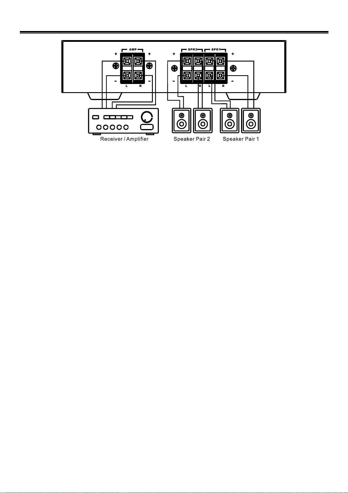
MAKING THE CONNECTIONS
Cautions:
‧Be sure your receiver/amplifier’s power is turned off before you make the connections.
‧Never let the speaker wire’s bare ends touch each other or the adjacent terminals on the Speaker Selection/Volume
Control System
‧Do not connect more than one pair of speakers to each set of terminals.
1. Flip open the desired
insert the speakers’ positive (+) wires into the corresponding
wires into the negative (black) terminals. Then flip the terminal ta bs down to secure the wires.
2. Flip open the
AMP terminals’ tabs on the back of the Speaker Selection/Volume Control System, then insert
your receiver/amplifier ’s output positive (+) wires into the
into the
AMP – negative (black) terminals. Then flip the tabs down to secure the wires.
SPK 1-2 terminals’ tabs on the back of the Speaker Selection/Volume Control System, then
SPK 1-2 positive (red) terminals, and negative (-)
AMP + positive (red) treminals, and output negative wires
Notes:
‧If your receiver/amplifier has more than one set of speaker terminals (A and B), connect the A output to the Speaker
Selection/Volume Control System. Do not connect anything to the B output. This prevents the receiver/amplifier
from driving an unusually low impedance load.
‧For the best results, we recommend 18-gauge, two-conductor speaker wire (not supplied) for most connections. Or,
if you plan to position the speakers farther than 80 feet from the Speaker Selection/Volume Control System, use
a heavier gauge of wire.
Page 2

Speaker Selection / Volume Control System
Your Speaker Selection/Volume Control System delivers independent volume control and on/off capability for up to two
pairs of speakers. You choose where and how loud the music is in a particular location ─ without affecting the entire
system.
The Speaker Selection/Volume Control System is equipped with premium 10-step volume controls that maintain full 30
dB dynamic range giving you the maximum adjustment capability.
Caution: This Speaker Selection/Volume Control System is limited to a maximum of 50 watts RMS per channel.
MAKING THE CONNECTIONS
Cautions:
‧Be sure your receiver/amplifier’s power is turned off before you make the connections.
‧Never let the speaker wire’s bare ends touch each other or the adjacent terminals on the Speaker Selection/Volume
Control System
‧Do not connect more than one pair of speakers to each set of terminals.
1. Flip open the desired
insert the speakers’ positive (+) wires into the corresponding
wires into the negative (black) terminals. Then flip the terminal ta bs down to secure the wires.
2. Flip open the
AMP terminals’ tabs on the back of the Speaker Selection/Volume Control System, then insert
your receiver/amplifier ’s output positive (+) wires into the
into the
AMP – negative (black) terminals. Then flip the tabs down to secure the wires.
SPK 1-2 terminals’ tabs on the back of the Speaker Selection/Volume Control System, then
SPK 1-2 positive (red) terminals, and negative (-)
AMP + positive (red) treminals, and output negative wires
Notes:
‧If your receiver/amplifier has more than one set of speaker terminals (A and B), connect the A output to the Speaker
Selection/Volume Control System. Do not connect anything to the B output. This prevents the receiver/amplifier
from driving an unusually low impedance load.
‧For the best results, we recommend 18-gauge, two-conductor speaker wire (not supplied) for most connections. Or,
if you plan to position the speakers farther than 80 feet from the Speaker Selection/Volume Control System, use
a heavier gauge of wire.
Page 3

OPERATION
Using the Protection Circuits
Your Speaker Selection/Volume Control System has an impedance correction circuit. This circuitry
assures that your receiver/amplifier monitors a safe operating load when playing 2 speaker pairs
simultaneously. Since most receiver/amplifier are not rated for use below a 4 ohm load. You will need to
press the
PROTECTION button whenever the overall system impedance falls below 4 ohms.
Playing One Pair of Speakers at a Time
1. Press in the switch 1 or 2 for the desired speakers.
2. Set the
3. Set the receiver/amplifier’s volume control to minimum by turning it fully counterclockwise. Then turn on the
receiver / amplifier and set its volume control slightly above the normal listening l evel.
4. To increase or decrease the remote speaker’s volume, turn the Speaker Selection/Volume Control System volume
control clockwise or counterclockwise.
PROTECTION button to the out position.
Playing T wo Pairs of Speakers at a Time
1. Press in the switches both 1 and 2.
2. If your two pairs of speakers are 8 ohm speakers then set the
3. If your two pairs of speakers are 4 ohm speakers then press the
4. Set the receiver/amplifier’s volume control to minimum by turning it fully counterclockwise. Then turn on the
receiver/ amplifier and set its volume control slightly above the normal listening level.
5. To increase or decrease the remote speaker’s volume, turn the Speaker Selection/Volume Control System volume
control clockwise or counterclockwise.
PROTECTION button to the out position.
PROTECTION button.
SPECIFICATIONS
Power Handling…………………………………50 Watts (RMS) per Channel
Attenuation………………………………………………….10-Position Control
1st Position (Fully Counterclockwise): Full-Off
2nd and 3rd Position: Attenuate 6 dB Per Step
4th to 9th Position: Attenuate 3 dB Per Step
10th Position: Full On
Channel Separation at 1 KHz……………………………………38 dB Normal
Crosstalk Between Channels at 1 KHz…………………………50 dB Normal
Speaker Terminal Wire Size………………………………………..14-22 AWG
Specifications are typical; i ndividual units might vary. Specification s are subject to change and improvement without
notice.
Page 4

OPERATION
Using the Protection Circuits
Your Speaker Selection/Volume Control System has an impedance correction circuit. This circuitry
assures that your receiver/amplifier monitors a safe operating load when playing 2 speaker pairs
simultaneously. Since most receiver/amplifier are not rated for use below a 4 ohm load. You will need to
press the
PROTECTION button whenever the overall system impedance falls below 4 ohms.
Playing One Pair of Speakers at a Time
1. Press in the switch 1 or 2 for the desired speakers.
2. Set the
3. Set the receiver/amplifier’s volume control to minimum by turning it fully counterclockwise. Then turn on the
receiver / amplifier and set its volume control slightly above the normal listening l evel.
4. To increase or decrease the remote speaker’s volume, turn the Speaker Selection/Volume Control System volume
control clockwise or counterclockwise.
PROTECTION button to the out position.
Playing T wo Pairs of Speakers at a Time
1. Press in the switches both 1 and 2.
2. If your two pairs of speakers are 8 ohm speakers then set the
3. If your two pairs of speakers are 4 ohm speakers then press the
4. Set the receiver/amplifier’s volume control to minimum by turning it fully counterclockwise. Then turn on the
receiver/ amplifier and set its volume control slightly above the normal listening level.
5. To increase or decrease the remote speaker’s volume, turn the Speaker Selection/Volume Control System volume
control clockwise or counterclockwise.
PROTECTION button to the out position.
PROTECTION button.
SPECIFICATIONS
Power Handling…………………………………50 Watts (RMS) per Channel
Attenuation………………………………………………….10-Position Control
1st Position (Fully Counterclockwise): Full-Off
2nd and 3rd Position: Attenuate 6 dB Per Step
4th to 9th Position: Attenuate 3 dB Per Step
10th Position: Full On
Channel Separation at 1 KHz……………………………………38 dB Normal
Crosstalk Between Channels at 1 KHz…………………………50 dB Normal
Speaker Terminal Wire Size………………………………………..14-22 AWG
Specifications are typical; i ndividual units might vary. Specification s are subject to change and improvement without
notice.
 Loading...