

Wintair AW-24CR3FM1 Owner’s Manual
ROOMAIRCONDITIONER
UseandCareManual
IN !
Thank you for purchasing an WINTAIR®room air conditioner. Please read this "Use and Care Manual" carefully
before installing and using this appliance. Keep this manual for future reference.
M cuasef)/ac_s_o con'par a_ea;on( co/sa_oWlNTAIR ® _ Ma a de )soy
Mar;tenmerto'ar_tesdeinstaary ,4 zaresteprod_cto Co_se_veesterran a paraconsutaroene futuro,
For Service Call 1 877 465 3566
Pars obtener servicio t@cnico_Ilame a! 1 877 465 3566
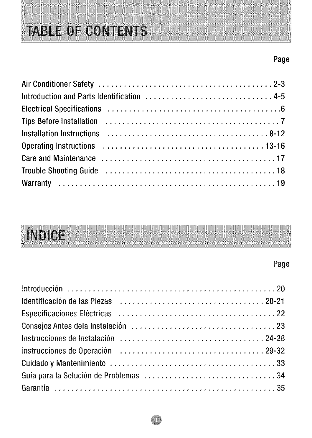
Page
Air Conditioner Safety ......................................... 2-3
Introduction and Parts Identification .............................. 4-5
Electrical Specifications ......................................... 6
Tips Before Installation ......................................... 7
Installation Instructions ...................................... 8-12
Operating Instructions ...................................... 13-16
Care and Maintenance ......................................... 17
Trouble Shooting Guide ........................................ 18
Warranty ................................................... 19
Page
Introducci6n ................................................. 20
Identificaci6n de las Piezas .................................. 20-21
Especificaciones EI6ctricas ..................................... 22
Consejos Antes dela Instalaci6n .................................. 23
Instrucciones de Instalaci6n .................................. 24-28
Instrucciones de Operaci6n .................................. 29-32
Cuidado y Mantenimiento ....................................... 33
Guia para la Soluci6n de Problemas ............................... 34
Garantia .................................................... 35
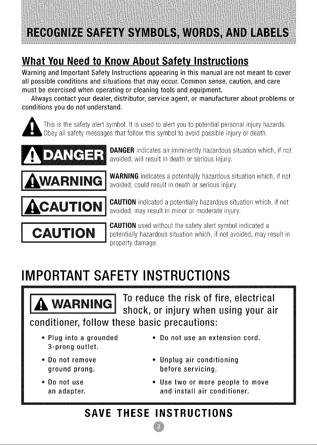
What YouNeed to KnowAbout Safety Instructions
Warning and important Safety instructions appearing in this manual are not meant to cover
all possible conditions and situations that may occur. Common sense, caution, and care
must be exercised when operating or cleaning tools and equipment.
Always contact your dealer, distributor, service agent, or manufacturer about problems or
conditions you do not understand.
This is tile safety alert symbol. It is used to alert you to potential personal injury hazards.
y all safety messages that follow this symbol to avoid possible injury or death.
_ ANGER indicates an imminently hazardous situation which, if not
_ ARNING indicates a potentially hazardous situation which, if not
_ AUTION indicated a potentially hazardous situation which, if not
_ CAUTION used without tile safety alert symbol indicated a
avoided, will result in death or serious injury.
avoided, could result in death or serious injury.
avoided, may result in minor or moderate injury.
potentially hazardous situation which, if not avoided, may result in
property damage.
IMPORTANTSAFETYINSTRUCTIONS
To reduce the risk of fire, electrical
shock, or injury when using your air
conditioner,follow these basic precautions:
• Plug into a grounded
3-prong outlet.
• DO not remove
ground prong.
• Do not use
an adapter.
SAVE THESE INSTRUCTIONS
* Do not use an extension cord.
Unplug air conditioning
before servicing.
Use two or more people to move
and install air conditioner.
• The air conditioner should be connected to the
appropriate electrical receptacle as shown in the
chart on Page 6 (Receptacle and Fuse Types).
The use of a time-delay fuse or time-delay circuit
breaker is recommended.
All wiring must comply with local and national
electrical codes and be installed by a qualified
electrician. Ifyou have any questions, contact
a qualified electrician.
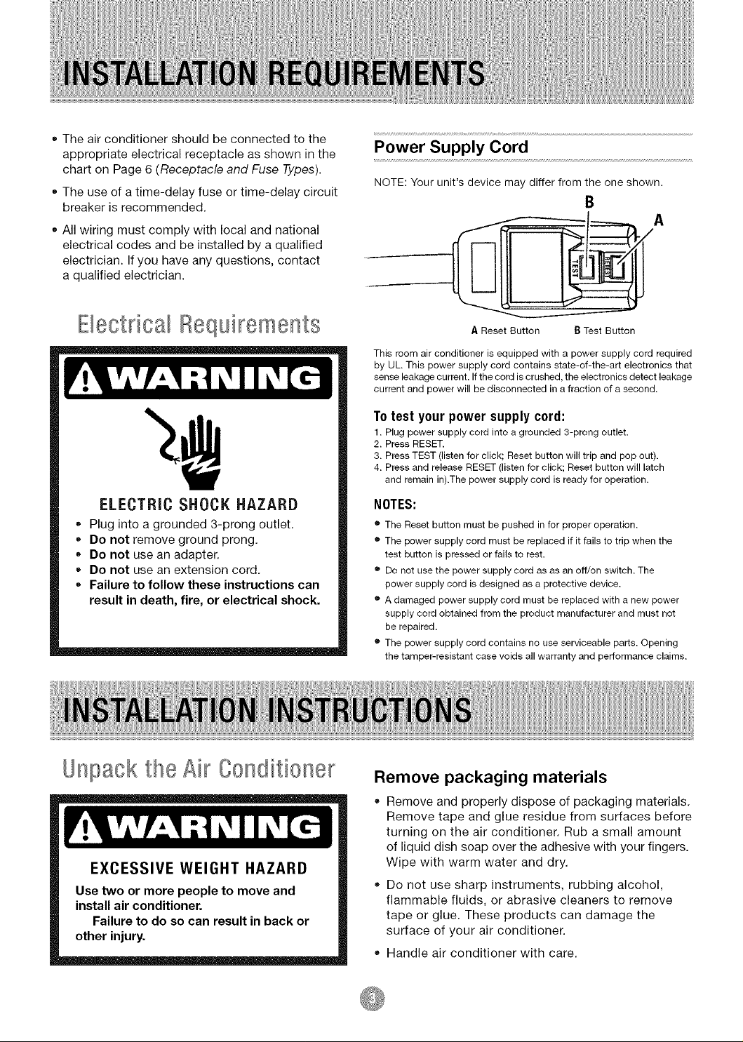
Power Supply Cord
NOTE: Your unit's device may differ from the one shown.
B
Ebct ical ,/equi ements
ELECTRIC SHOCK HAZARD
• Plug into a grounded 3-prong outlet.
De not remove ground prong.
Do not use an adapter.
• Do not use an extension cord.
• Failure to follow these instructions can
result in death, fire, or electrical shock.
A Reset Button B Test Button
This room air conditioner is equipped with a power supply cord required
by UL. This power supply cord contains state-of-the-art electronics that
sense leakage current. If the cord is crushed, the electronics detect leakage
current and power will be disconnected in a fraction of a second.
To test your power supply cord:
1. Plug power supply cord into a grounded 3-prong outlet.
2. Press RESET.
3. Press TEST (listen for click; Reset button will trip and pop out).
4. Press and release RESET (listen for click; Reset button will latch
and remain in).The power supply cord is ready for operation.
NOTES:
• The Reset button must be pushed in for proper operation.
• The power supply cord must be replaced if it fails to trip when the
test button is pressed or fails to rest.
• Do not use the power supply cord as as an off/on switch. The
power supply cord is designed as a protective device.
• A damaged power supply cord must be replaced with a new power
supply cord obtained from the product manufacturer and must not
be repaired.
• The power supply cord contains no use serviceable parts. Opening
the tamper-resistant case voids all warranty and performance claims.
Unpack the Air Conditioner
Remove packaging materials
Remove and properly dispose of packaging materials.
Remove tape and glue residue from surfaces before
turning on the air conditioner. Rub a small amount
of liquid dish soap over the adhesive with your fingers.
Wipe with warm water and dry.
Do not use sharp instruments, rubbing alcohol,
flammable fluids, or abrasive cleaners to remove
tape or glue. These products can damage the
surface of your air conditioner.
Handle air conditioner with care.
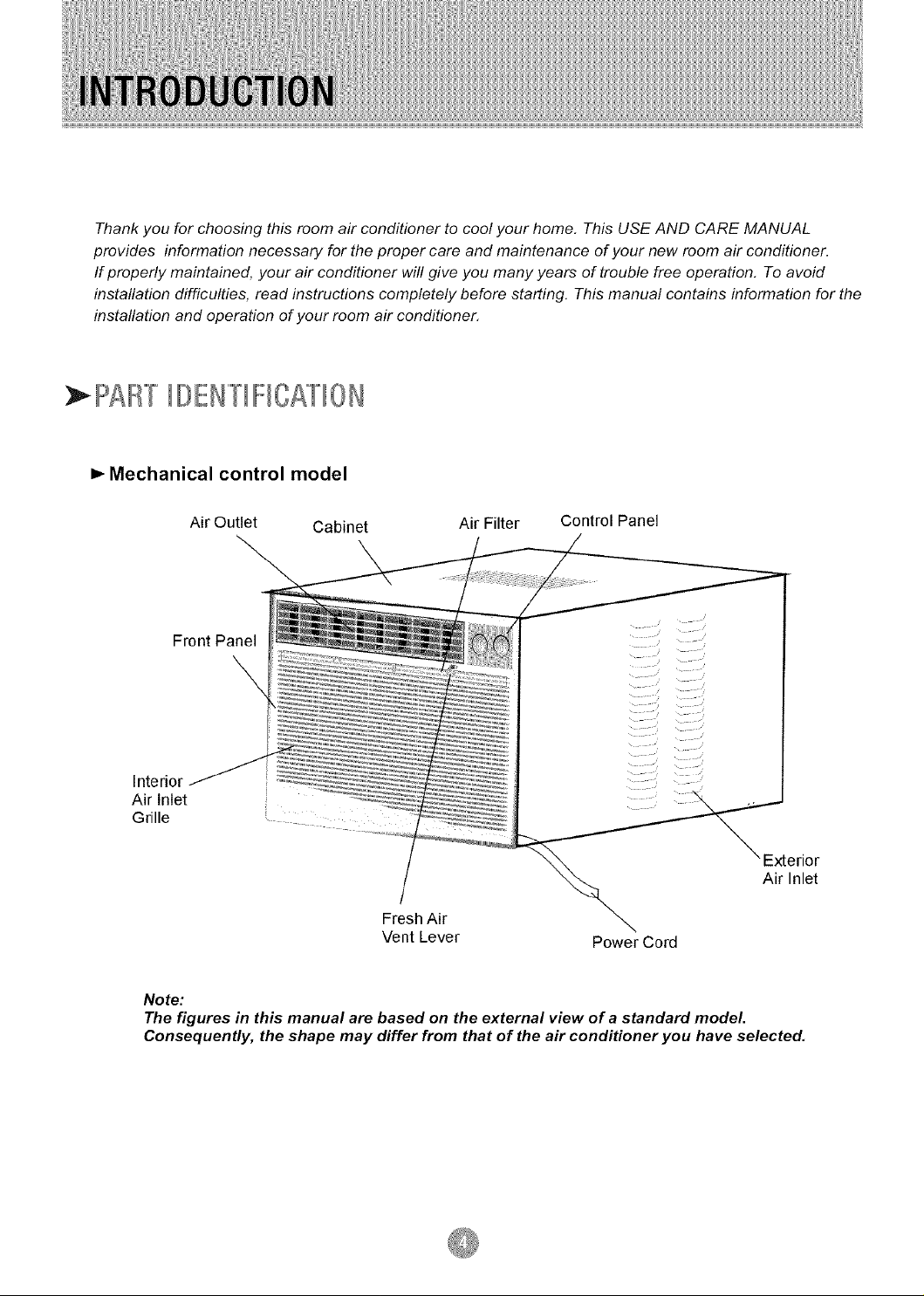
Thank you for choosing this room air conditioner to cool your home. This USE AND CARE MANUAL
provides information necessary for the proper care and maintenance of your new room air conditioner.
If properly maintained, your air conditioner will give you many years of trouble free operation, To avoid
instaflation difficulties, read instructions completely before starting. This manual contains information for the
instaflation and operation of your room air conditioner.
PAl/""[IDE/"'[IFICATI0/
=,-Mechanical control model
Air Outlet Cabinet
Front Panel
Air Filter Control Panel
\
Interior
Air Inlet
Grille
Fresh Air
Vent Lever
Note:
The figures in this manual are based on the external view of a standard model.
Consequently, the shape may differ from that of the air conditioner you have selected.
Power Cord
Exterior
Air Inlet
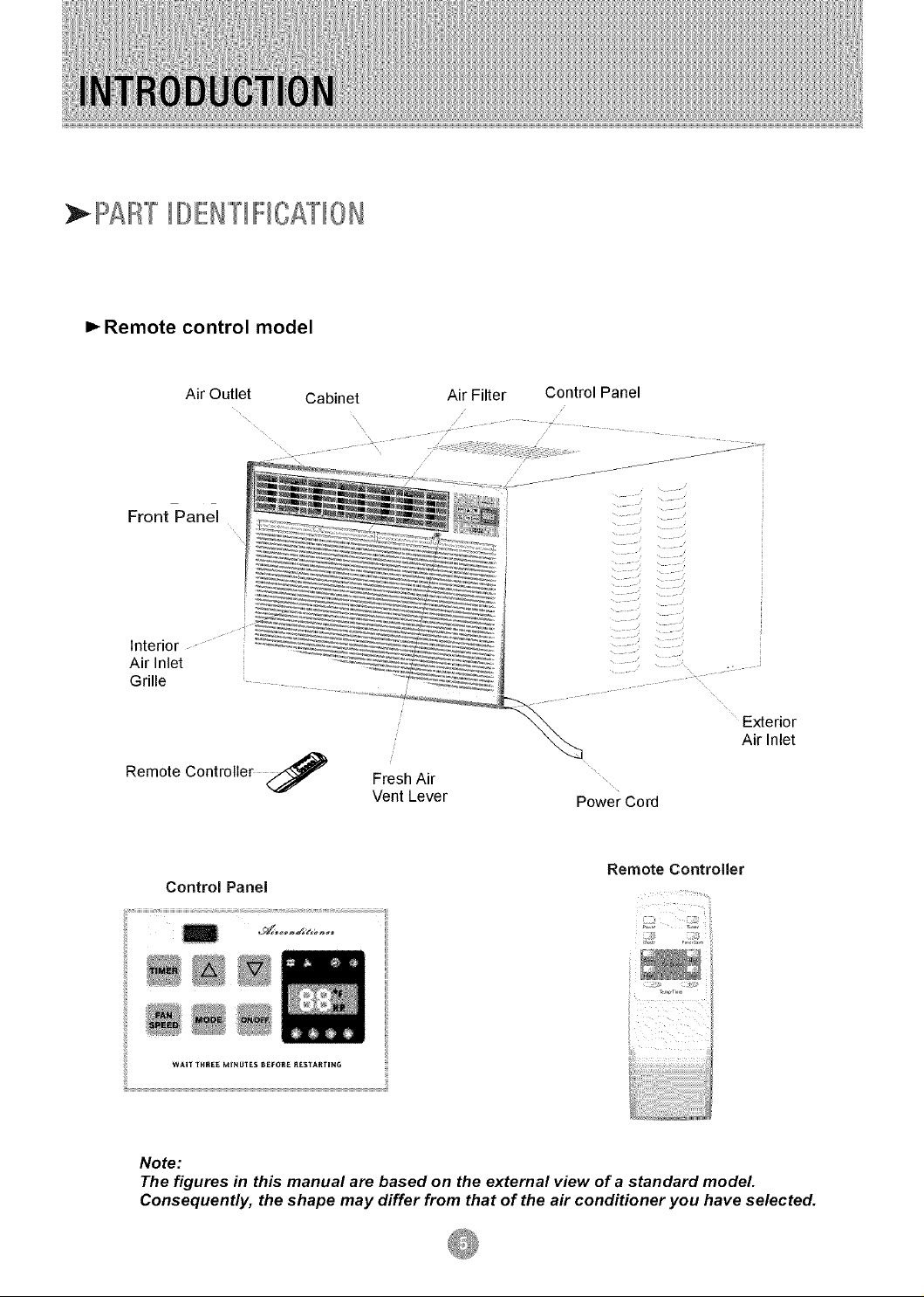
PAF'/TIOEN""[IFICATI0N
=,-Remote control model
Air Outlet
Front Panel
interior
Air Inlet
Grille
Remote Controller <_
Control Panel
Cabinet Air Filter Control Panel
Exterior
Air Inlet
Fresh Air
Vent Lever Power Cord
Remote Controller
WAIf _RSEEM_NUTES6_FOSE_tES_ARfING
Note:
The figures in this manual are based on the external view of a standard model.
Consequently, the shape may differ from that of the air conditioner you have selected.
1. All wiring must comply with local and national
electrical codes and must be installed by a
licensed electrician. If you have any questions
regarding the following instructions, contact a
licensed electrician.
2. Check available power supply and resolve any
wiring problems BEFORE installing and operating
this unit.
If the air conditioner has a serial plate rating
of 115 volts and up to and including 7.5 amps,
the unit maybe on a fuse or circuit breaker
with other devices. However, the maximum
amps on all devices for that fuse or circuit
breaker can not exceed the amps of the fuse
for the circuit breaker.
3. For your safety and protection, this unit is
grounded through the power cord when
plugged into a matching wall outlet. If you are
not sure whether your wall outlet is properly
grounded, please consult a licensed
electrician.
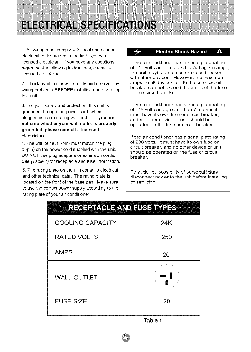
4. The wall outlet (3-pin) must match the plug
(3-pin) on the power cord supplied with the unit.
DO NOT use plug adapters or extension cords.
See (Table 1)for receptacle and fuse information.
5. The rating plate on the unit contains electrical
and other technical data. The rating plate is
located on the front of the base pan. Make sure
to use the correct power supply according to the
rating plate of your air conditioner.
COOLING CAPACITY
RATED VOLTS
If the air conditioner has a serial plate rating
of 115 volts and greater than 7.5 amps it
must have its own fuse or circuit breaker,
and no other device or unit should be
operated on the fuse or circuit breaker.
If the air conditioner has a serial plate rating
of 230 volts, it must have its own fuse or
circuit breaker, and no other device or unit
should be operated on the fuse or circuit
breaker.
To avoid the possibility of personal injury,
disconnect power to the unit before installing
or servicing.
IIIIIII
24K
250
AMPS
WALL OUTLET
FUSE SIZE
20
20
Table 1
Your RoomAir Conditioner unit is designed to
be highly efficient and save energy. Follow these
recommendations for greater efficiency.
1. Select thermostat setting that suits your
comfort needs and leave the thermostat at
that chosen setting.
2. The air filter is very efficient in removing airborne
particles. Keep the air filter clean. Typically, the filter
should be cleaned once a month. More
frequent cleaning may be necessary depending
on outdoor and indoor air quality.
3. Use drapes, curtains, or shades to keep direct
sunlight from heating your room, but DO NOT
obstruct the air conditioner. Allow three (3) inches
around unit to circulate.
4. Start your air conditioner before outdoor
air becomes hot/cold and uncomfortable. This
avoids an initial period of discomfort while
the unit is cooling or heating off the room.
5. When outdoor temperature is cool
enough, use HIGH or LOW FAN
only. This circulates indoor air, providing
some cooling comfort, and utilizes less
electricity than when operating on a
cooling setting.
Your RoomAir Conditioner was designed
for easy installation in a single or double-hung
window. NOTE: This unit is NOT designed for
vertical (slider type) windows.
pr!'
To avoid installation/operating difficulties,
read the instructions thoroughly.
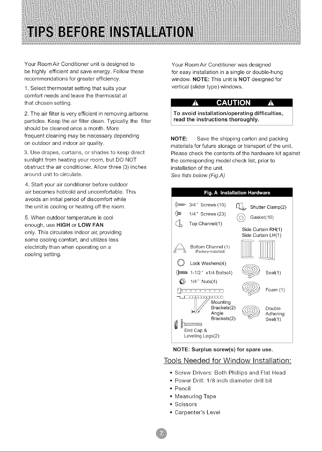
NOTE: Save the shipping carton and packing
materials for future storage or transport of the unit.
Please check the contents of the hardware kit against
the corresponding model check list, prior to
installation of the unit.
See lists below. (Fig.A)
314" Screws (10)
(_ 1/4" Screws (23)
Top Channel(1 )
Bottom Channel (1)
(Factory-instalbd)
O Lock Washers(4)
1-1/2" xl/4 Bolts(4)
114" Nuts(4)
ooooooooooool
Shutter Clamp(2)
(_ Gasket(10)
Side Curtain RH(1)
Side Curtain LH(1)
Seal(l)
Foam (1)
U ounting
_ Brackets(2)
End Cap &
Leveling Legs(2)
NOTE: Surplus screw(s) for spare use.
Brackets(2)
Angle
DoubleAdhering
Seal(1 )
Tools Needed for Window Installation:
,, Screw Drivers: Both Phillips and Flat Head
,, Power Drill: 1/8 inch diameter drill bit
,, Pencil
,, Measuring Tape
,, Scissors
,, Carpenter's Level
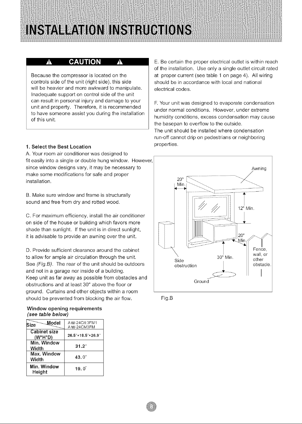
Becausethecompressorislocatedonthe
controlssideoftheunit(rightside),thisside
willbeheavierandmoreawkwardtomanipulate.
Inadequatesupportoncontrolsideoftheunit
canresultinpersonalinjuryanddamagetoyour
unitandproperty.Therefore,itisrecommended
tohavesomeoneassistyouduringtheinstallation
ofthisunit.
1. Select the Best Location
A. Your room air conditioner was designed to
fit easily into a single or double hung window. However,
since window designs vary, it may be necessary to
make some modifications for safe and proper
installation.
B. Make sure window and frame is structurally
sound and free from dry and rotted wood.
C. For maximum efficiency, install the air conditioner
on side of the house or building which favors more
shade than sunlight. If the unit is in direct sunlight,
it is advisable to provide an awning over the unit.
E. Be certain the proper electrical outlet is within reach
of the installation. Use only a single outlet circuit rated
at proper current (see table 1 on page 4). All wiring
should be in accordance with local and national
electrical codes.
F. Your unit was designed to evaporate condensation
under normal conditions. However, under extreme
humidity conditions, excess condensation may cause
the basepan to overflow to the outside.
The unit should be installed where condensation
run-off cannot drip on pedestrians or neighboring
properties.
Awning
/
D. Provide sufficient clearance around the cabinet
to allow for ample air circulation through the unit.
See (Fig.B). The rear of the unit should be outdoors
and not in a garage nor inside of a building.
Keep unit as far away as possible from obstacles and
obstructions and at least 30" above the floor or
ground. Curtains and other objects within a room
should be prevented from blocking the air flow.
Window opening requirements
see table below)
_ AW-24CR3FM 1
Cabinet size
(W*H*D)
IVlin. Window
Width
Max. Window
Width
Min. Window
Height
AW-24CM3FM
26.5".18.5"'26.9"
31.2"
43,0"
19,0"
X 30" Min.
Side
obstruction
Ground
Fig.B
Fence,
wall, or
other
obstacle.
I
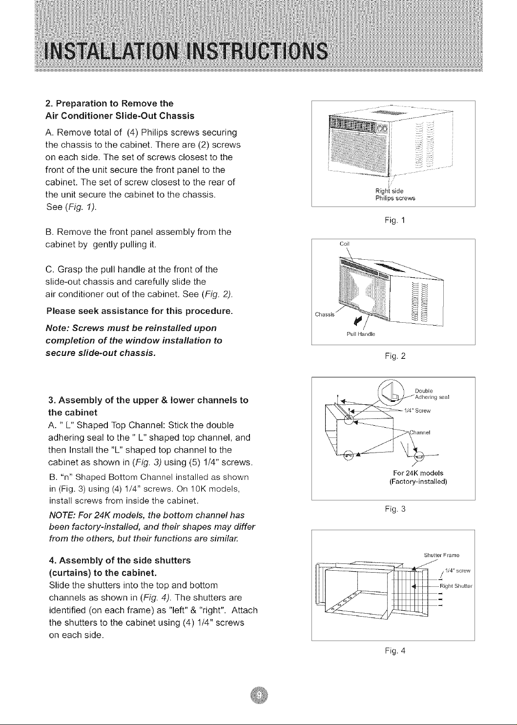
2.Preparation to Remove the
Air Conditioner Slide-Out Chassis
A. Remove total of (4) Philips screws securing
the chassis to the cabinet. There are (2) screws
on each side. The set of screws closest to the
front of the unit secure the front panel to the
cabinet. The set of screw closest to the rear of
the unit secure the cabinet to the chassis.
See (Fig. 1).
B. Remove the front panel assembly from the
cabinet by gently pulling it.
C. Grasp the pull handle at the front of the
slide-out chassis and carefully slide the
air conditioner out of the cabinet. See (Fig. 2).
Please seek assistance for this procedure.
Note: Screws must be reinstalled upon
completion of the window installation to
secure sfide-out chassis,
Right side
Phi]ips screws
Fig. 1
Coil
Chassis _
Fig. 2
3. Assembly of the upper & lower channels to
the cabinet
A. " L" Shaped Top Channel: Stick the double
adhering seal to the " L" shaped top channel, and
then Install the "L" shaped top channel to the
cabinet as shown in (Fig. 3) using (5) 1/4" screws.
B. "n" Shaped Bottom Channel installed as shown
in (Fig. 3) using (4) 1/4" screws. On 10K models,
install screws from inside the cabinet.
NOTE: For 24K models, the bottom channel has
been factory-instafled, and their shapes may differ
from the others, but their functions are similar.
4. Assembly of the side shutters
(curtains) to the cabinet.
Slide the shutters into the top and bottom
channels as shown in (Fig. 4). The shutters are
identified (on each frame) as "left" & "right". Attach
the shutters to the cabinet using (4) 1/4" screws
on each side.
' Adhering seal
Double
1/4" Screw
For 24K models
(Factory-installed)
Fig. 3
Shutter Fiame
Fig. 4
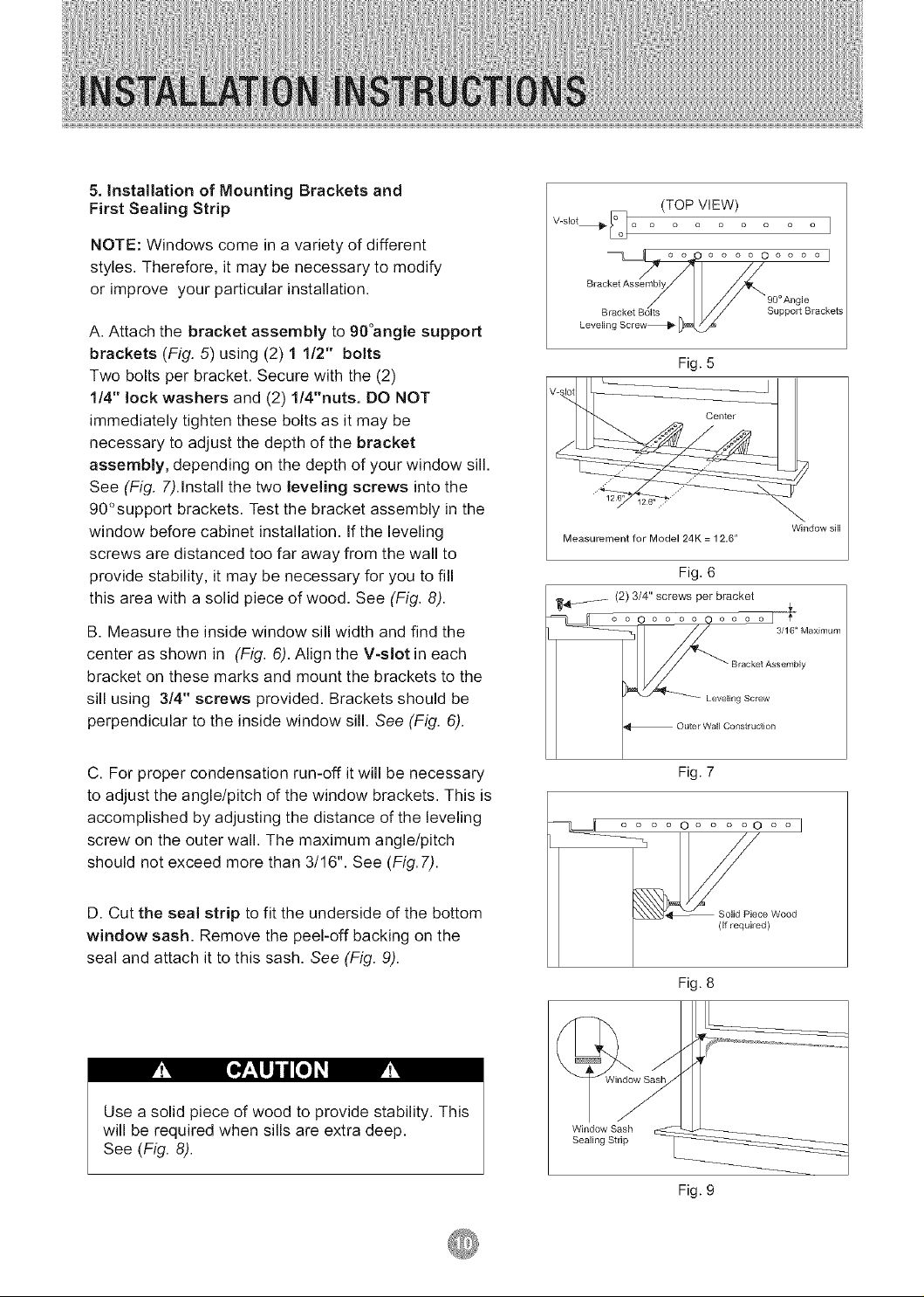
5. Installation of Mounting Brackets and
First Sealing Strip
NOTE: Windows come in a variety of different
styles. Therefore, it may be necessary to modify
or improve your particular installation.
A. Attach the bracket assembly to 90°angle support
brackets (Fig. 5) using (2) 1 1/2" bolts
Two bolts per bracket. Secure with the (2)
1/4" lock washers and (2) 1/4"nuts. DO NOT
immediately tighten these bolts as it may be
necessary to adjust the depth of the bracket
assembly, depending on the depth of your window sill.
See (Fig. 7).Install the two leveling screws into the
90°support brackets. Test the bracket assembly in the
window before cabinet installation. If the leveling
screws are distanced too far away from the wall to
provide stability, it may be necessary for you to fill
this area with a solid piece of wood. See (Fig. 8).
B. Measure the inside window sill width and find the
center as shown in (Fig. 6). Align the V-slot in each
bracket on these marks and mount the brackets to the
sill using 3/4" screws provided. Brackets should be
perpendicular to the inside window sill. See (Fig. 6).
(TOP VIEW)
V-slot_ [_ ...... 1
/ /
Bracket Assembly
Leve Support Brackets
Fig. 5
Measurement for Model 24K = 12,6"
Fig. 6
_._ (2) 3/4" screws per bracket ,r
C. For proper condensation run-off it will be necessary
to adjust the angle/pitch of the window brackets. This is
accomplished by adjusting the distance of the leveling
screw on the outer wall. The maximum angle/pitch
should not exceed more than 3/16". See (Fig.7).
D. Cut the seal strip to fit the underside of the bottom
window sash. Remove the peel-off backing on the
seal and attach it to this sash. See (Fig. 9).
M [o : ujjl[o M
Use a solid piece of wood to provide stability. This
will be required when sills are extra deep,
See (Fig. 8).
Fig. 7
.... o .... ooo I
_c_)Wood
Fig. 8
Fig. 9
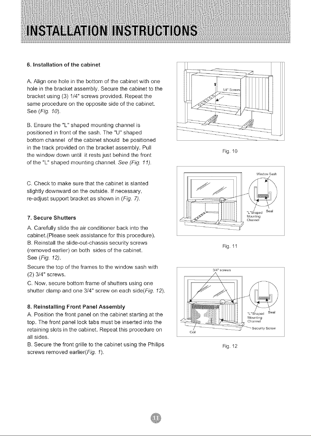
6. Installation of the cabinet
A. Align one hole in the bottom of the cabinet with one
hole in the bracket assembly. Secure the cabinet to the
bracket using (3) 1/4" screws provided. Repeat the
same procedure on the opposite side of the cabinet.
See (Fig. 10).
B. Ensure the "L" shaped mounting channel is
positioned in front of the sash. The "U" shaped
bottom channel of the cabinet should be positioned
in the track provided on the bracket assembly. Pull
the window down until it rests just behind the front
of the "L" shaped mounting channel. See (Fig. 11).
C. Check to make sure that the cabinet is slanted
slightly downward on the outside. If necessary,
re-adjust support bracket as shown in (Fig. 7).
7. Secure Shutters
A. Carefully slide the air conditioner back into the
cabinet.(Please seek assistance for this procedure),
B. Reinstall the slide-out-chassis security screws
(removed earlier) on both sides of the cabinet,
See (Fig. 12).
Secure the top of the frames to the window sash with
(2) 3/4" screws.
C. Now, secure bottom frame of shutters using one
shutter clamp and one 314" screw on each side(Fig. 12).
Fig. 10
Fig. 11
3/4" screws
Window Sash
"L"Shaped Seal
Mounting
Channel
8. Reinstalling Front Panel Assembly
A. Position the front panel on the cabinet starting at the
top. The front panel lock tabs must be inserted into the
retaining slots in the cabinet, Repeat this procedure on
all sides,
B. Secure the front grille to the cabinet using the Philips
screws removed earlier(Fig. 1).
Coil
Fig. 12
MounSng
Channel
Seal
 Loading...