


OPERATIONS MANUAL
PCM-GPS
NOTE: This manual has been designed and created for use as part of the WinSystems Technical Manuals
CD and/or the WinSystems website. If this manual or any portion of the manual is downloaded, copied or
emailed, the links to additional information (i.e. software, cable drawings) may be inoperable.
WinSystems reserves the right to make changes in the circuitry
and specications at any time without notice.
Copyright 2009 by WinSystems. All Rights Reserved.

REVISION HISTORY
P/N 403-0321-000
ECO Number Date Code Rev Level
ORIGINATED 050408 B
07-150 080306 B.1
08-145 080924 B.2
09-45 091110 B.3

Table of Contents
Visual Index – Quick Reference i
Top View - Connectors i
Introduction 1
General Information 1
Features 1
General Description 1
Functional Capability 2
I/O Address Selection 2
Interrupt Routing 2
On-board PPS Usage 3
External PPS Usage 3
GPS Almanac Battery 3
GPS Antenna 3
Optional Cellular Modem Interface 4
Optional IEEE 802.15.4 Support
Optional Modem56K Interface 4
PC/104 Bus Interface 5
PCM-GPS Programming Reference 6
Introduction 6
TSIP Software Interface 6
4
Software Drivers & Examples 11
Jumper Reference 12
I/O Address Selection 13
Interrupt Routing 13
External PPS Usage 14
GPS Almanac Battery 14
Specications 15
WARRANTY REPAIR INFORMATION 16
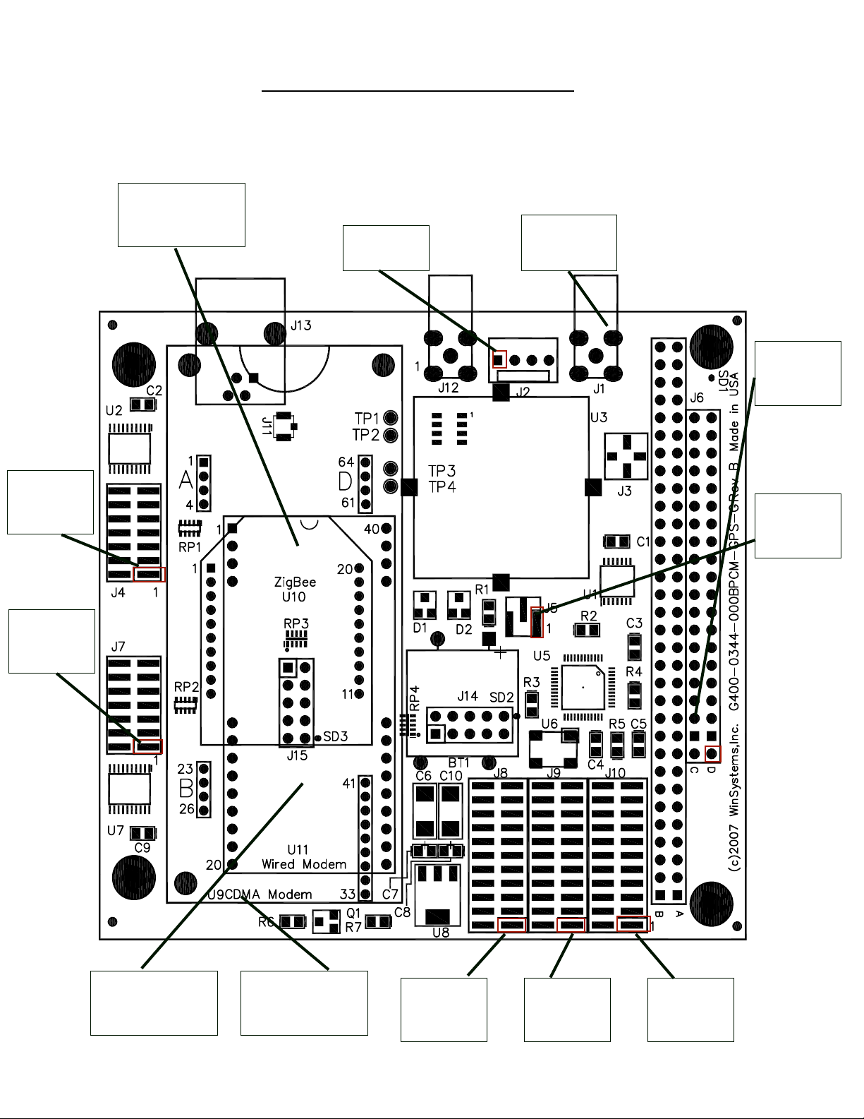
J4
Serial Port 1
(GPS)
Visual Index – Quick Reference
Top View - Connectors
For the convenience of the user, a copy of the Visual Index has been provided with
direct links to connector and jumper conguration data.
U10
ZigBee Interface
J2
External
Battery
J1
External
Antenna
Connection
J6
PC/104 Bus
J5
External/
Interal Battery
Selection
J7
Serial Port 2
(Modem)
U11
MODEM56K
Interface
U9
Cellular Modem
Interface
J8
Serial Port 2
(Modem)
J9
Serial Port 1
(GPS)
J10
Pulse Per
Second (PPS)
091110 OPERATIONS MANUAL PCM-GPS i

Introduction
This manual is intended to provide the necessary information regarding conguration and
usage of the PCM-GPS board. WinSystems maintains a Technical Support Group to help
answer questions regarding usage or programming of the board. For answers to questions not
adequately addressed in this manual, contact Technical Support at (817) 274-7553, Monday
through Friday, between 8 AM and 5 PM Central Standard Time (CST).
General Information
Features
• Dual function PC/104-compatible board with GPS and optional Cell Modem support
GPS Features
Trimble Lassen® receiver module
TSIP, TAIP and NEMA 0183 protocols supported
Pulse output support for accurate time standard
External power antenna connection via a Standard SMA
On-board battery retains GPS Almanac
Cell Modem (optional)
• GSM/GPRS and CDMA standard support
• Socket support for MultiTech
• Recognizes standard AT commands
• Alarm management, phone book management and Short Message Service (SMS) support
ZigBee Support (optional)
• IEEE 802.15.4 ZigBee™ Wireless Interface
• Up to 1 mile line of sight range
• 2.4 GHz ISM frequency band
• 60 mW, 100 mW EIRP power output
®
wireless module
Modem Support (optional)
• 56 kbps PC/104 Modem
• V.42, MNP Class2-4 error correction
• V.42bis, MNP 5 compression
• Integrated DAA provides compliance to global telephone standards
• Built-in fuse and SiDactor
• Caller ID Detection
• Parallel phone detection
• DTMF dialing
Industrial Operating Temperature Range
• -40°C to 85°C
Form Factor
• PC/104-compliant
• 3.60 in x 3.80 in (90 mm x 96 mm)
Additional Specications
• Programmable address and interrupt setting support
General Description
The PCM-GPS from WinSystems is a PC/104 module incorporating the Lassen IQ
12-channel parallel tracking GPS receiver from Trimble®. The GPS receiver is interfaced to an
on-board 16550 compatible DUART which receives the serial data sent by the GPS module.
The data output as supplied by the factory is in TSIP format making it compatible with all offthe-shelf mapping, navigation, and geocaching application software. Supplied C source code
assists the integrator in creating custom applications utilizing the PCM-GPS. The PCM-GPS also
supports the Trimble receiver’s high precision Pulse Per Second (PPS) output for use in critical
time keeping or synchronizing applications. The PCM-GPS also supports the CDMA and GPRS/
GSM cellular SocketModems® from Multi-Tech Systems®. These modems, when combined with
the GPS positioning data, can provide a “phone home” function to report its current location.
091110 OPERATIONS MANUAL PCM-GPS 1
Functional Capability
Visual
Index
Visual
Index
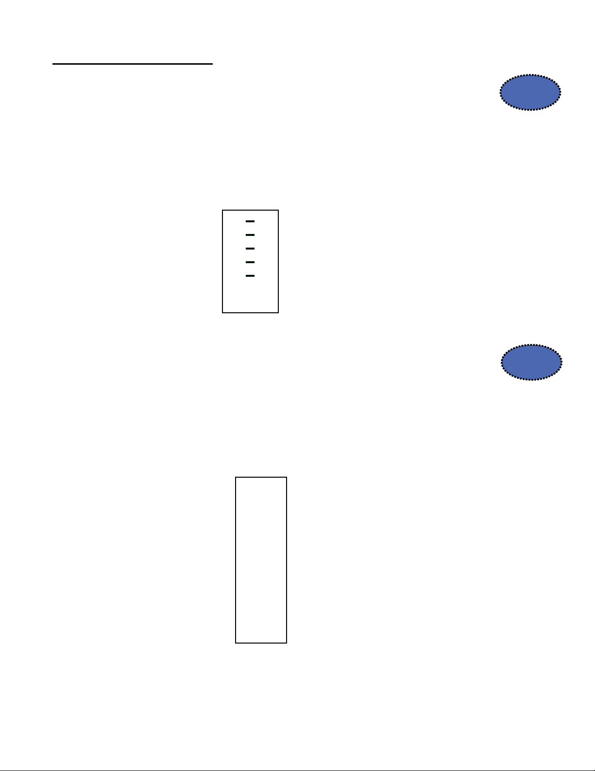
I/O Address Selection
The PCM-GPS requires eight consecutive I/O addresses beginning on an 8-byte
boundary for each of the two on-board serial channels. The jumper blocks at J4 and
J7 allow selection of the primary (GPS) and secondary serial (SocketModem®) port
I/O addresses respectively. Address selection is made by placing a jumper on the
jumper pair for the address bit, if a 0 is desired or leaving the jumper pair open if a
1 is required for the desired address. The illustration below shows the relationship
between the address bits and the jumper position and a sample jumpering for an
address of 300H.
J4/J7
A3
A4
A5
A6
A7
A8
A9
I/O Base Address Select jumper
J4/J7 shown jumpered for 300H
1 o o 2
3 o o 4
5 o o 6
7 o o 8
9 o o 10
11 o o 12
13 o o 14
To disable a port, place a jumper on all 7 positions 9Address = 000H.
Interrupt Routing
The PCM-GPS can source up to three unique on-board interrupts. Two are available for
each of the serial interfaces and a third for the Pulse Per Second (PPS) interrupt from
the GPS. The jumper blocks at J8, J9, and J10 allow for routing of the interrupts for
the SocketModem®, the GPS serial output, and the PPS source respectively.
To route an interrupt to a source, place a jumper at the desired IRQ position. Unused
sources should be left unjumpered. Each source must have its own unique interrupt.
J8/J9/J10
J8 - SocketModem
J9 - GPS
J10 - PPS Interrupt
1 o o 2
®
3 o o 4
5 o o 6
7 o o 8
9 o o 10
11 o o 12
13 o o 14
15 o o 16
17 o o 18
19 o o 20
21 o o 22
IRQ3
IRQ4
IRQ5
IRQ6
IRQ7
IRQ9
IRQ10
IRQ11
IRQ12
IRQ14
IRQ15
091110 OPERATIONS MANUAL PCM-GPS 2

On-board PPS Usage
Visual
Index
Visual
Index
Visual
Index
The GPS receiver generates a 4 µs wide positive pulse every second with the leading
edge synchronized to UTC time within ±95 nanoseconds when valid position xes are
being reported. WinSystems’ on-board implementation degrades this accuracy by
buffering the PPS output using a 74HCT14 Schmitt trigger device which also inverts the
signal. Since PC interrupts are edge-triggered on the rising edge, the actual interrupt
will occur 4 µs plus the inverter propagation time later (typical 17 ns). This added delay
is actually insignicant to any software synchronizing routines as the entire hardware
interrupt acknowledgment process will consume many additional microseconds in a bestcase scenario. The PPS signal begins immediately at power-up and continues even if the
receiver loses GPS lock. The drift of the signal without GPS lock is unspecied.
External PPS Usage
The PPS signal, in addition to being available on-board for interrupt generation, is also
terminated at two polarities on the J2 connector. The negative pulsed output at pin 2 of
J2 is driven by a 74HCT14 inverter with a typical propagation delay of 17 ns.
The positive signal is available on pin 3 of J2 and is double-buffered by the same type
device for a typical delay of 34 ns. Either of these signals can be used by external
hardware for time synchronization purposes.
J2
1 o
2 o
3 o
4 o
EXTERNAL BAT+
PPS OUT (Neg)
PPS OUT (Pos)
GND
GPS Almanac Battery
The PCM-GPS is shipped with a 350 mAH 3.5V Lithium battery. This battery is used to
retain GPS Almanac and Ephemeris data which provides for a greatly improved time
to position x from power-up. With the battery available, and valid Almanac data, the
time for a valid x is reduced from under 2 minutes to under 20 seconds. The Trimble®
published current draw on the battery backup line is 19 µA typical at 25ºC. Alternately, an
external battery may be connected between Pin 1 (+) and Pin 4 (-) of J2. An externally
connected battery should be rated at 3.5V ±.2V. The jumper block at J5 is used to select
the GPS backup battery source as shown below. The jumper may be removed or moved
to the external position for long-term storage of boards for battery preservation.
J5
On-board battery selection Off-board connector selection
1 2 3
o o o
J5
External Battery J2 (pin 1)
1 2 3
o o o
GPS Antenna
The PCM-GPS requires an external outdoor antenna with a clear view of the sky in order
to receive and track satellites in the GPS constellation. J1 is a standard SMA connector for
attachment of the antenna. It must be an active antenna powered by the 3.3V supplied by
the GPS and with a typical gain of 28 dB. WinSystems offers an optional magnetic mount
antenna P/N ANTENNA-MAGNETIC built by Trimble® for this module. Other antennas
meeting the above specications should work as well.
091110 OPERATIONS MANUAL PCM-GPS 3

Optional Cellular Modem Interface
Visual
Index
Visual
Index
Visual
Index
The PCM-GPS supports optional CDMA and GPRS/GSM cellular SocketModem™ modules
from Multi-Tech Systems (www.multitech.com). The modem modules are installed in
the U9 position and secured with screws and standoffs, Velcro, or double-stick tape as
desired. The SocketModems™ use the secondary serial port on the PCM-GPS and are
controlled in software by a number of AT commands. Cellular data service must be
purchased from one of the supported cellular providers. Contact Multi-Tech or one of their
distributors directly for answers to all questions regarding the installation, conguration,
programming or usage of the Multi-Tech cellular modem modules.
The Multi-Tech part numbers for compatible SocketModems™ are :
MTSMC-C CDMA Modem
MTSMC-G GSM/GPRS Modem
Note: The PCM-GPS can support either: cellular modem, ZigBee® or Modem56K
modules. WinSystems can package the PCM-GPS board with either add-on module.
Please contact a WinSystems Applications Engineer for additional information.
Optional IEEE 802.15.4 Support
The PCM-GPS supports an optional IEEE 802.15.4 ZigBee® wireless interface from Digi
(www.digi.com) . This interface provides low-power wireless networking solutions.
ZigBee® modules are installed in the U10 position, a 20-pin socket which is compatible
with Digi XBee™/XBee-PRO™ OEM RF modules. The ZigBee® interface is PC/104compatible, and is congurable using AT and API Command modes.
The ZigBee® transceiver is congured as either an XBee™ or XBee-PRO™ module that is
wired to a SMA RF connector on the edge of the board. The difference between the two
modules is the amount of power consumed (1 mW vs. 60 mW) and signal range.
Note: The PCM-GPS can support either: cellular modem, ZigBee® or Modem56K
modules. WinSystems can package the PCM-GPS board with either add-on module.
Please contact a WinSystems Applications Engineer for additional information.
For more information on XBee™, see the ZigBee® Product manual.
Optional Modem56K Interface
The U11 position provides support for Wintec®’s PC/104-compatible 56 kbps modem.
This modem replaces WinSystems’ PCM-33.6 board and supports data rates up to 56,000
bps. The modem also supports MNP error correction and data compression. Based on
the DSP hardware chipset, the modem uses the AT command set to control its operation
and register settings.
Note: The PCM-GPS can support either: cellular, ZigBee® or Modem56K modules.
WinSystems can package the PCM-GPS board with either add-on module. Please contact
a WinSystems Applications Engineer for additional information.
091110 OPERATIONS MANUAL PCM-GPS 4

PC/104 Bus Interface
Visual
Index
The PCM-GPS connects to the processor through the PC/104 bus connector at J6. The
pin denitions for the 8-bit and 16-bit halves of J6 are provided here for reference.
Refer to the PC/104 Bus Specication for specic signal and mechanical specications.
D0 o o C0
GND
+5V
GND
GND
D1 o o C1
D2 o o C2
D3 o o C3
D4 o o C4
D5 o o C5
D6 o o C6
D7 o o C7
D8 o o C8
D9 o o C9
D10 o o C10
D11 o o C11
D12 o o C12
D13 o o C13
D14 o o C14
D15 o o C15
D16 o o C16
D17 o o C17
D18 o o C18
D19 o o C19
MEMCS16#
IOCS16#
IRQ10
IRQ11
IRQ12
IRQ15
IRQ14
DACK0#
DRQ0
DACK5#
DRQ5
DACK6#
DRQ6
DACK7#
DRQ7
MASTER#
# = Active Low Signal
GND
SBHE#
LA23
LA22
LA21
LA20
LA19
LA18
LA17
MEMR#
MEMW#
SD8
SD9
SD10
SD11
SD12
SD13
SD14
SD15
KEY
IOCHK#
SD7
SD6
SD5
SD4
SD3
SD2
SD1
SD0
IOCHRDY
AEN
SA19
SA18
SA17
SA16
SA15
SA14
SA13
SA12
SA11
SA10
SA9
SA8
SA7
SA6
SA5
SA4
SA3
SA2
SA1
SA0
GND
A1 o o B1
A2 o o B2
A3 o o B2
A4 o o B4
A5 o o B5
A6 o o B6
A7 o o B7
A8 o o B8
A9 o o B9
A10 o o B10
A11 o o B11
A12 o o B12
A13 o o B13
A14 o o B14
A15 o o B15
A16 o o B16
A17 o o B17
A18 o o B18
A19 o o B19
A20 o o B20
A21 o o B21
A22 o o B22
A23 o o B23
A24 o o B24
A25 o o B25
A26 o o B26
A27 o o B27
A28 o o B28
A29 o o B29
A30 o o B30
A31 o o B31
A32 o o B32
GND
RESET
+5V
IRQ9
-5V
DRQ2
-12V
SRDY#
+12V
KEY
SMEMW#
SMEMR#
IOW#
IOR#
DACK3#
DRQ3
DACK1#
DRQ1
REFRESH#
BCLK
IRQ7
IRQ6
IRQ5
IRQ4
IRQ3
DACK2#
TC
BALE
+5V
OSC
GND
GND
NOTES:
1. Rows C and D are not required on 8-bit modules.
2. B10 and C19 are key locations. WinSystems uses key pins as connections to GND.
3. Signal timing and function are as specied in ISA specication.
4. Signal source/sink current differ from ISA values.
091110 OPERATIONS MANUAL PCM-GPS 5

PCM-GPS Programming Reference
Software Interface 3
The serial port driver in the iQ_CHAT Tool Kit matches the Lassen iQ
GPS receiver serial port characteristics. The TSIPPRNT program
converts binary data logged with the iQ_CHAT program into text that
may be printed and displayed. Both of these tools are included in the
Software Developer’s Toolkit.
Warning – When using the TSIP protocol to change port assignments or
settings, confirm that your changes do not affect the ability to
communicate with the receiver (e.g., selecting the PC COM port settings
that do not match the receiver’s, or changing the output protocol to TSIP
while not using iQ_CHAT).
Introduction
The software standard for commercial GPS receivers is TSIP format (www.trimble.com). The
Trimble Lassen® IQ GPS module is also capable of transmitting and receiving serial data in a
Trimble proprietary format known as TSIP. This is a binary protocol which ordinarily runs at
9600 baud, an 8-bit word, and odd parity. PCM-GPS boards as shipped, default to this TSIP
standard.
The Trimble Lassen® IQ GPS module is also capable of transmitting and receiving serial data
in NMEA 0183 format. This is a simple ASCII, serial communications protocol that denes how
data is transmitted. Users requiring a NMEA interface to the GPS should see the Software
Drivers & Examples section of this manual or contact WinSystems Technical Support for details
on converting the PCM-GPS to NMEA.
TSIP Software Interface
091110 OPERATIONS MANUAL PCM-GPS 6

Software Interface 3
3.2 Communicating with the Lassen iQ GPS Receiver
The Lassen iQ GPS Receiver supports three message protocols: TSIP,
TAIP, and NMEA. Communication with the module is through two
CMOS compatible, TTL level serial ports. The port characteristics can
be modified to accommodate your application requirements. Port
parameters can be stored in non-volatile memory (FLASH) which
does not require backup power. Table 3.1. lists the default port
characteristics.
3.2.1 Software Tools
The Software Tools provided on the Starter Kit CD-ROM include both
user friendly Windows and DOS applications to facilitate
communication with the receiver, via the Trimble Standard Interface
Protocol (TSIP). This CD also includes sample C source code and
reusable routines to aid in developing applications.
Note – The TSIP, TAIP, and NMEA protocols are discussed beginning
on page 42 of this chapter, and in the Appendices of this document.
091110 OPERATIONS MANUAL PCM-GPS 7

Software Interface 3
The serial port driver in the iQ_CHAT Tool Kit matches the Lassen iQ
GPS receiver serial port characteristics. The TSIPPRNT program
converts binary data logged with the iQ_CHAT program into text that
may be printed and displayed. Both of these tools are included in the
Software Developer’s Toolkit.
Warning – When using the TSIP protocol to change port assignments or
settings, confirm that your changes do not affect the ability to
communicate with the receiver (e.g., selecting the PC COM port settings
that do not match the receiver’s, or changing the output protocol to TSIP
while not using iQ_CHAT).
Software Interface 3
3.3.2 TSIP Data Output Modes
TSIP is the default protocol for Port 1 on the Lassen iQ GPS receiver.
This binary language offers users a wide variety of commands and
reports. TSIP enables the Lassen iQ GPS receiver to operate in two
data output modes, both available during operation. In Query Mode,
packet data is returned in response to input query packets. In
Automatic Mode, a selected group of data packets is output
continuously at two fixed rates – every second and every five seconds.
The format and ensemble of the automatic output packets is
configured using packets 0x35, 0x70, and 0x8E-20 (see Appendix A
for packet details). Packet settings are stored in BBRAM. They can
also be saved in non-volatile memory (Flash) using command packet
0x8E-26. See Appendix A for additional information on Flash storage
for custom operation.
3.3.3 Default TSIP Output Settings
Default 0x35 setting (byte 0=2, 1= 2, 2=0, 3=0):
• Position and velocity data precision: single precision floating point
• Position output option and format (byte 0 setting):
– Latitude – radian
– Longitude – radian
– Altitude – meters (WGS-84)
• No super-packet output
• Velocity output option and format:
– East Velocity – meters/sec.; + for East
– North Velocity – meters/sec.; + for North
– Up Velocity – meters/sec.; + for Up
• Timing
– GPS Time Output
– PPS Always ON
091110 OPERATIONS MANUAL PCM-GPS 8

3 Software Interface
Default 0x70 setting (byte 0=1, 1=1. 2=1. 3=0):
• Position-Velocity Dynamic Filter enabled
• Position-Velocity static Filter enabled
• Altitude Filter enabled
Default 0x8E-20 setting (byte 1 = 1):
• 0x8F-20 output is included in the super-packet for automatic output
IF packet 0x35 selects the super-packet for automatic output
options
3.3.4 Automatic TSIP Output Packets (fixed rate)
One second interval:
• 0x4A – (1) GPS position fix; (2) clock bias and time of fix; {20
byte format}
• 0x56 – velocity fix
• 0x6D – (1) list of satellites used for position fixes; (2) PDOP,
HDOP, VDOP; (3) fix mode
• 0x82 – DGPS position fix mode
Five second interval:
• 0x41 – (1) GPS time of the week (seconds); (2) extended GPS
week number; (3) GPS UTC offset (seconds)
• 0x46 – health of receiver
• 0x4B – (1) Machine/Code ID; (2) Real-time-clock availability
status; (3) almanac validity status; (4) having super-packet support
status
091110 OPERATIONS MANUAL PCM-GPS 9

3 Software Interface
Default 0x70 setting (byte 0=1, 1=1. 2=1. 3=0):
• Position-Velocity Dynamic Filter enabled
• Position-Velocity static Filter enabled
• Altitude Filter enabled
Default 0x8E-20 setting (byte 1 = 1):
• 0x8F-20 output is included in the super-packet for automatic output
IF packet 0x35 selects the super-packet for automatic output
options
3.3.4 Automatic TSIP Output Packets (fixed rate)
One second interval:
• 0x4A – (1) GPS position fix; (2) clock bias and time of fix; {20
byte format}
• 0x56 – velocity fix
• 0x6D – (1) list of satellites used for position fixes; (2) PDOP,
HDOP, VDOP; (3) fix mode
• 0x82 – DGPS position fix mode
Five second interval:
• 0x41 – (1) GPS time of the week (seconds); (2) extended GPS
week number; (3) GPS UTC offset (seconds)
• 0x46 – health of receiver
• 0x4B – (1) Machine/Code ID; (2) Real-time-clock availability
status; (3) almanac validity status; (4) having super-packet support
status
Software Interface 3
3.3.5 Packet Output Order
After power up or a software reset (packet 0x1E), seven start-up
packets are sent, only once, by the receiver in this order: 45, 46, 4B,
4A, 56, 41, 82
Before position fixes are available, the 1 second and 5 second interval
packets are sent in this order, periodically:
• Every one second for 5 seconds: 6D, 82
• Every five seconds 41, 46, 4B
When position fixes are available, the 1 second and 5 second interval
packets are sent in this order, periodically:
• Every one second for 4 seconds: 4A, 56, 6D, 82
• Every 5 seconds: 4A, 56, 41, 46, 4B, 6D, 82
091110 OPERATIONS MANUAL PCM-GPS 10

Software Drivers & Examples
Documentation
Trimble® Manual Reprint LassenManual.pdf
GSM Programming Quick Start Guide
Examples
PCM-GPS Example Program with source nmea3.zip
GPS Conguration Utility IQ_CHAT.EXE
Monitoring Software including TSIPCHAT and TSIPPRNT iQ_Monitor_V1-52.exe
NMEA Software Standard nmea.pdf
Examples
(Source Code Sample)
TSIP iQSource.zip
gsm_quickstart.pdf
091110 OPERATIONS MANUAL PCM-GPS 11

Jumper Reference
Drawings ONLY - for more detailed information on these parts, refer to the
descriptions shown previously in this manual.
J4
Serial Port 1
(GPS)
U10
Cellular
Modem
Interface
J2
External
Battery
J1
External
Antenna
Connection
J6
PC/104 Bus
J5
External/
Interal Battery
Selection
J7
Serial Port 2
(Modem)
U11
MODEM56K
Interface
U9
Cellular Modem
Interface
J8
Serial Port 2
(Modem)
J9
Serial Port 1
(GPS)
J10
Pulse Per
Second (PPS)
091110 OPERATIONS MANUAL PCM-GPS 12

I/O Address Selection
J4/J7
I/O Base Address Select jumper
J4/J7 shown jumpered for 300H
1 o o 2
3 o o 4
5 o o 6
7 o o 8
9 o o 10
11 o o 12
13 o o 14
A3
A4
A5
A6
A7
A8
A9
To disable a port, place a jumper on all 7 positions 9Address = 000H.
Interrupt Routing
To route an interrupt to a source place a jumper at the desired IRQ position. Unused
sources should be left unjumpered. Each source must have its own unique interrupt.
J8/J9/J10
IRQ3
IRQ4
IRQ5
IRQ6
IRQ7
IRQ9
IRQ10
IRQ11
IRQ12
IRQ14
IRQ15
J8 - SocketModem
J9 - GPS
J10 - PPS Interrupt
1 o o 2
®
3 o o 4
5 o o 6
7 o o 8
9 o o 10
11 o o 12
13 o o 14
15 o o 16
17 o o 18
19 o o 20
21 o o 22
091110 OPERATIONS MANUAL PCM-GPS 13

External PPS Usage
GPS Almanac Battery
J2
1 o
EXTERNAL BAT+
2 o
PPS OUT (Neg)
3 o
PPS OUT (Pos)
4 o
GND
J5
1 2 3
o o o
J5
1 2 3
o o o
091110 OPERATIONS MANUAL PCM-GPS 14

Specications
Electrical
Bus Interface :PC/104 16-Bit, stackthrough
VCC :+5V required, 50 mA typical, GPS module only. Add 20 mA typical
for Trimble® magnetic mount antenna
I/O Addressing :10-Bit user jumperable address. Each board uses 2 sets
of 8 consecutive I/O addresses.
PPS Output :1PPS (4 µs width) TTL Level both positive
and negative available
Mechanical
Dimensions :3.6” X 3.8” (90 mm x 96 mm)
Weight :2.5 oz (70.87 gm)
PC Board :FR-4 Epoxy glass with 2 signal layers 2 power
planes, screened component legend, and plated
through holes.
Jumpers :0.020” square posts on 2.0 mm centers
Connectors :PPS/External Battery : Molex 4 pin
:GPS: 50Ω SMA with power for antenna
PC/104 :64-pin, 0.100” (32-pin double row)
:40-pin, 0.100” (20-pin double row)
Environmental
Operating Temperature :-40°C to +85°C (without optional cell modem installed)
Noncondensing humidity :5% to 95%
MTBF :54.11 yrs rate based upon MIL-HDBK-217C data
091110 OPERATIONS MANUAL PCM-GPS 15

WARRANTY REPAIR INFORMATION
WARRANTY
(http://www.winsystems.com/company/warranty.cfm)
WinSystems warrants to Customer that for a period of two (2) years from the date of
shipment any Products and Software purchased or licensed hereunder which have been
developed or manufactured by WinSystems shall be free of any material defects and shall
perform substantially in accordance with WinSystems’ specications therefore. With respect
to any Products or Software purchased or licensed hereunder which have been developed or
manufactured by others, WinSystems shall transfer and assign to Customer any warranty
of such manufacturer or developer held by WinSystems, provided that the warranty, if any,
may be assigned. Notwithstanding anything herein to the contrary, this warranty granted by
WinSystems to the Customer shall be for the sole benet of the Customer, and may not be
assigned, transferred or conveyed to any third party. The sole obligation of WinSystems for
any breach of warranty contained herein shall be, at its option, either (i) to repair or replace
at its expense any materially defective Products or Software, or (ii) to take back such Products
and Software and refund the Customer the purchase price and any license fees paid for the
same. Customer shall pay all freight, duty, broker’s fees, insurance charges for the return of
any Products or Software to WinSystems under this warranty. WinSystems shall pay freight
and insurance charges for any repaired or replaced Products or Software thereafter delivered
to Customer within the United States. All fees and costs for shipment outside of the United
States shall be paid by Customer. The foregoing warranty shall not apply to any Products of
Software which have been subject to abuse, misuse, vandalism, accidents, alteration, neglect,
unauthorized repair or improper installations.
THERE ARE NO WARRANTIES BY WINSYSTEMS EXCEPT AS STATED HEREIN, THERE ARE NO
OTHER WARRANTIES EXPRESS OR IMPLIED INCLUDING, BUT NOT LIMITED TO, THE IMPLIED
WARRANTIES OF MERCHANTABILITY AND FITNESS FOR A PARTICULAR PURPOSE, IN NO EVENT
SHALL WINSYSTEMS BE LIABLE FOR CONSEQUENTIAL, INCIDENTIAL OR SPECIAL DAMAGES
INCLUDING, BUT NOT LIMITED TO, DAMAGES FOR LOSS OF DATA, PROFITS OR GOODWILL.
WINSYSTEMS’ MAXIMUM LIABILITY FOR ANY BREACH OF THIS AGREEMENT OR OTHER CLAIM
RELATED TO ANY PRODUCTS, SOFTWARE, OR THE SUBJECT MATTER HEREOF, SHALL NOT
EXCEED THE PURCHASE PRICE OR LICENSE FEE PAID BY CUSTOMER TO WINSYSTEMS FOR
THE PRODUCTS OR SOFTWARE OR PORTION THEREOF TO WHICH SUCH BREACH OR CLAIM
PERTAINS.
WARRANTY SERVICE
1. To obtain service under this warranty, obtain a return authorization number. In the
United States, contact the WinSystems’ Service Center for a return authorization number.
Outside the United States, contact your local sales agent for a return authorization number.
2. You must send the product postage prepaid and insured. You must enclose the products
in an anti-static bag to protect from damage by static electricity. WinSystems is not responsible
for damage to the product due to static electricity.
091110 OPERATIONS MANUAL PCM-GPS 16
 Loading...