

WINSTON GROUP EAGLE V42-DD Operating Instructions Manual
OPERATING INSTRUCTIONS FOR THE
EAGLE V42-DD HOT-AIR WELDING TOOL
CONGRATULATIONS! You have purchased an Eagle, a tool that is designed and manufactured to assist
you with a quality seam weld. NOTE: The Winston Group does not warrant seam performance. We supply
a tool which provides heat, speed, and pressure. You, as the operator, select the correct combination of
these three components and, like all tools, the most important factor to a quality seam is your skill and
experience in setting up and using the Eagle.
WARRANTY CARD. A postage-paid warranty card is included in the shipping box. Please fill it out so that
we can provide you any new product information or "tips" for better welding. The serial number of your unit
is located on the handle of the gun assembly.
READ THESE INSTRUCTIONS
Any new tool requires familiarity. Take
fifteen minutes of time to get
acquainted with your purchase. These
instructions are intended to guide you
through connection, operation, trouble
shooting, and maintenance. If you have
any questions or problems in start-up,
give us a call at:
1-630-231-0419
sales@winstongroup.com
THE WINSTON GROUP LTD
1092 Carolina Drive, Suite 1 Phone:1-630-231-0419
West Chicago, Illinois 60185 Fax: 630-231-0429
www.winstongroup.com
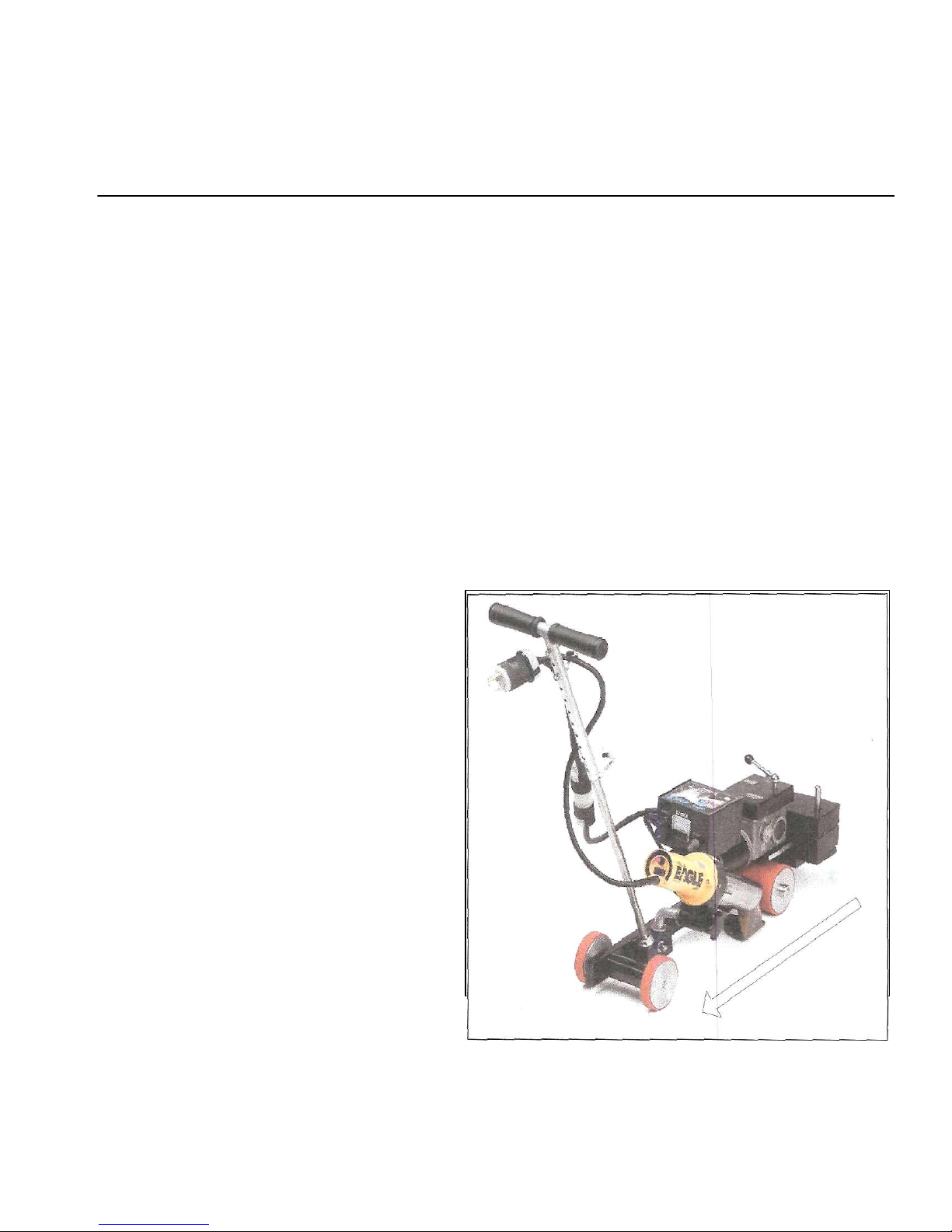
COOL DOWN 10 MINUTES
CAUTION AS V42DD MOVES BACKWARD
Fig. #1

I. UNPACKING, ASSEMBLY AND CONNECTION .
A. UNPACKING.
Your new V42DD Hot Air Welder is delivered to you in a sturdy, reuseable polymer tool box. The custom
designed foam base and spacers assure that your machine is protected and arrives ready to assemble
and use.
Remove the machine by lifiting it straight up and out and set it on a horizontal surface. The 2 additional
10 lb. weights are packed in cut-outs under the machine with foam covers on top.
Remove the foam covers from the weights and place them into the cut-outs for reuse after removing the
weights. Return all of the foam pieces to the box for later use during transportation and storage.
The only assembly required is to thread the handle into its base on the frame and tighten it down with the
lock nut, and attach an appropriate twist-lock plug to the end of the cord as described below.
B. ELECTRICAL POWER REQUIREMENTS.
Rating: 230VAC at 20 AMP The Eagle will operate within a range of 210VAC to 250VAC. Checking the
voltage at the point of unit plug-in is critical to the performance of your welder. You can perform the
voltage check with built in voltmeter.
Caution: YOU ARE WORKING WITH HIGH VOLTAGE EQUIPMENT. DEATH OR SERIOUS INJURY
MAY OCCUR DURING OR AFTER EQUIPMENT CONNECTION. UTILIZE A QUALIFIED
ELECTRICIAN.
Generators: Minimum 7,500 Watt Portable Generators should be used as a power source for each Eagle
V42DD automatic unit in use. Building electrical outlets are a poor source of voltage because they are too
unpredictable. Even when they are dedicated circuits, power spikes and drops can occur, resulting in
sub-standard equipment operation.
A Minimum 7,500 Watt watt capacity for the generator provides a measure of protection against
insufficient voltage. Remember, the Eagle utilizes 4,200 watts so the guage and length of your extension
cord will affect the wattage requirement.
Extension Cords: Extension cord should be at least 10 Gauge, 3 wire, grounded cable.
Do not splice lengths of cable together. This is a serious safety hazard, and can cause a poor connection,
resulting in sub-standard machine performance. Maximum Extension Cord Lengths:
Voltage @ power source 10 Gauge, 3 wire 12 Gauge, 3 wire
208VAC 100 Feet 50 Feet
220VAC 300 Feet 100 Feet
230VAC 400 Feet 200 Feet
240VAC 500 Feet 300 Feet
C. PLUG CONNECTION.
A Three-prong(L6-30) Twist Lock plug with a rating of 30 Amps and 250VAC is required.
Eagle is shipped with a L6-30 plug (Part#HBL2621). An extension cord is required between generator
and eagle. A plug and receptacle with a rating of 30 Amps and 250VAC must be purchased and properly
installed. The purchased plug must fit the generator outlet (usually L14-30).
100 feet 10 gauge, 3wires extension cord furnished with L14-30 Plug and L6-30 Receptacle can be
purchased with the Eagle Unit. (Part#10-3-100)
The white and black wires from the cord set of the welder must be connected to the appropriate "X" and
"Y" terminals in the plug to obtain the proper voltage. The green wire must be connected to the ground
terminal of the purchased plug.
The voltmeter on the control box must read 210 Volts as a minimum and 250 Volts as a maximum
for proper operation.
-2-
D. ADDING THE WEIGHT KIT, AND CHECKING THE NOZZLE.
If recommended by the membrane manufacturer, add the 20 pound weight kit. Most membrane
manufacturers require the weights for welding. The amount of weight is a function of the type of
membrane, the type of insulation material and its thickness.
Weight Kit:To add the weight kit, simply slide the two weights over the preinstalled pins on the platform
over the pressure wheel. A third 10 pound weight (Part# 8622) may be added if required.
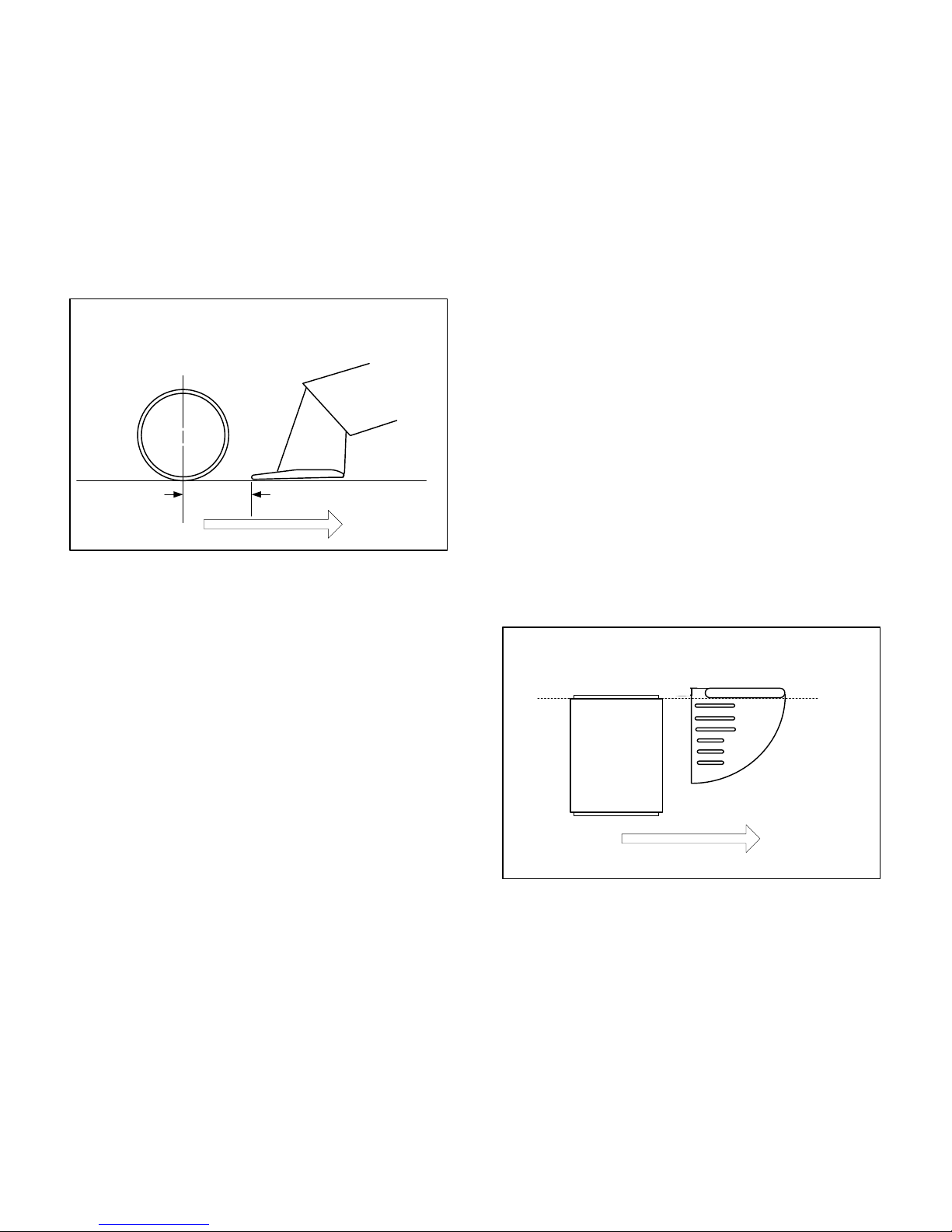
A- Welding Nozzle-Offset Alignment. Check
the distance between the vertical centerline of
the compression roller and the tip of the nozzle.
The distance should normally be 21/4"-21/2" (5560mm) from the centerline of the roller.
-3-
21/4" - 21/2"
Compression
Wheel
Nozzle
Nozzle
Compression
Wheel
B- Welding Nozzle In-line Alignment: Check the
alignment of the welding nozzle to the compression
wheel as shown in Fig. #2A. The inside edge of the
compression wheel should be in line with the inside
edge of the throat of the welding nozzle as shown
in Figure #2B. Proper alignment of the welding
nozzle to the compression wheel is accomplished
by adjusting the thumb wheel (Illustration #23 on
the part sheet) on the frame of the unit.
Fig. #2A
Fig. #2B
COOL DOWN 10 MINUTES

Fig. #3
Checking The Control Box Plugs
Each connector is "keyed" or "indexed" for proper alignment when attached.
The drive motor plug should be securely connected to the lower outlet on the left side of the control
box.
-4-
Drive Motor
connection
Speed Control
Knob
Main Power Input
30A 250V (L6-30)Twist-Lock Plug Furnished
II. OPERATION
A. POSITIONING OF WELDER
(For modified Bitumens APP or SBS)
The pressure roller should be positioned so that it
rolls fully on the surface of the top sheet, about 1/4"
inside the edge of the shelf. The edge of the roller
should not hang over the edge to keep it from
picking up the liquefied asphalt. (See Fig. #4).
THREADING THE HANDLE.
Thread the handle to the back of the welder. Tighten down the locking bolt so that the handle is firmly
bolted to the unit.
Put gear lever to drive to move the welder.
(CAUTION) - Lifting the welder by the lever can break off the lever.
Fig. #4
Drive Motor
Lever
Main Power
Switch
AC Input
Voltage
Indicator
Handle
COMPRESSION
WHEEL
0.25"
Bleed-Out
 Loading...