

Winstart WS-07U Installation Manual

Model WS-07U
TWO WAY LCD REMOTE CAR STARTER WITH ALARM
INSTALLATION GUIDE
1

2
WIRING DESCRIPTION
6 PIN Primary Starter Harness
RED
12V constant wire (12V positive input) connect to a 12V constant, 30A fuse built-in
RED
12V constant wire (12V positive input) connect to a 12V constant, 30A fuse built-in
YELLOW
12V positive auxiliary output for 2
nd
ignition, 2nd accessory, 2nd starter (see option # 5), 20A fuse built-in.
BLUE
Accessories wire (12V positive output) connect to accessory wire that controls the heater/air
conditioning fan
GREEN
Starter wire (12V positive output) connect to starter wire
ORANGE
Ignition wire (12V positive output) connect to main ignition
4 PIN Harness
BLACK
Ground wire, Important connect to a proper ground
BLUE
IGNITION OUTPUT 1A
GREEN / BLACK
500 mA Negative Parking Light
GREEN
15 A Positive Parking Light
10 PIN Harness
ORANGE
OUTPUT #5: 500mA negative pulse for slide door #1. It can be programmed as window
open/close or latching ON/OFF or negative parking light (see option # 22)
YELLOW
OUTPUT #2: 500mA constant negative

3
WIRING DESCRIPTION
10 PIN Harness
RED / WHITE
Horn or siren wire (500mA negative output) connects to horn or siren. Require a relay if siren is
used
YELLOW / BLUE
OUTPUT #1 (500mA negative output) give a pulse to disarm factory alarm
PINK
OUTPUT # 3: 500mA negative output, give a pulse to rearm factory alarm or open Sliding Door
#2 or window open/close or latching ON/OFF (see option # 21)
GREEN / BLACK
OUTPUT# 4: 500mA negative output for trunk opener or Transponder by-pass (see option # 8)
WHITE / BLACK
Starter kill disable wire (500mA negative output) connect to starter kill relay
BLUE / RED
OUTPUT #6: 500mA negative 2
nd
ignition output or 2nd slide door (see option #25)
WHITE / GREEN
Unlock wire (500mA negative output) See central door lock connection diagram
WHITE / RED
Lock wire (500mA negative output) See central door lock connection diagram
6 PIN Harness
BLUE
Hand brake wire (negative input) connect to the switched side of hand brake switch (for veh i cle
with manual transmission only)
BLUE / WHITE
Door trigger negative input, connect to negative door switch
BROWN
Hood wire (negative input) connect to hood pin switch
GREEN / YELLOW
Negative Trunk INPUT

4
WIRING DESCRIPTION
6 PIN Harness
PURPLE
TACH wire (AC input) connect to TACH signal wire (coil or injector)
WHITE
Brake wire (12V positive input) connect to the switched side of the brake pedal switch
5 PIN Harness Transponder module
RED
Output +12V
BLACK
GROUND
YELLOW
Output #2 : 500 mA negative constant
GREEN
NOT USED
WHITE
Door trigger positive input, connect to positive door switch
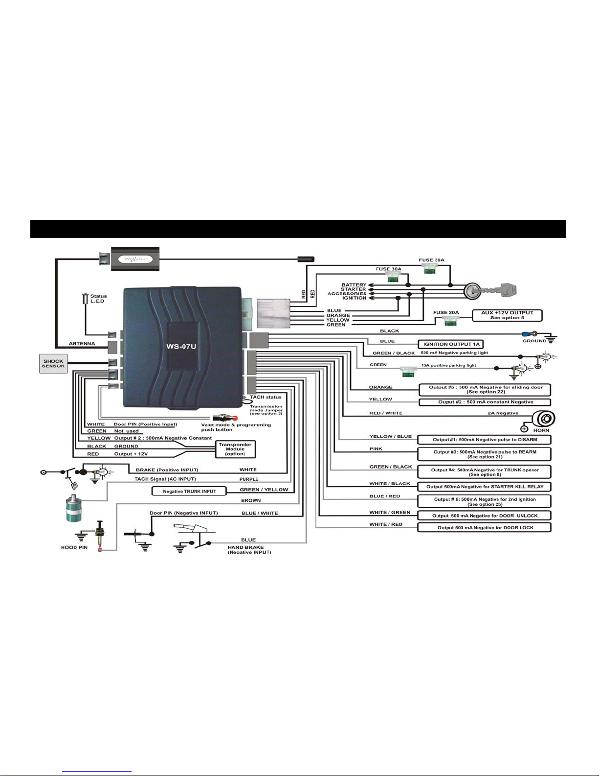
WIRING DIAGRAM
5

CENTRAL DOOR LOCK CONNECTION
DIAGRAM 1:
REVERSE POLARITY TYPE
DIAGRAM 2:
NEGATIVE TYPE
DIAGRAM 3:
ADDING DOOR LOCK ACTUATOR
6
 Loading...