

winsonic MFM1905S-EN30C User Manual

User’s Manua
- Model #MFM1905S-EN30C
WINSONIC ELECTRONICS Co., LTD
No.290-1, Wen Chung Rd., Taoyuan City, Taiwan, R.O.C
l:+886-3-3704789
ax:+886-3-3704722
E-mail:sales@ewinsonic.com
www.ewinsonic.com
Te
F

AD Board Specification
Panel Specification
Safety Instruction
Product Installation
Contents
General Description
Optical Specifications
Absolute Maximum Ratings
Electrical Specifications
Assembly
Trouble Shooting
3
4
5
25
5
11
12
6
32
33
Safety Instruction
Read and follow these instructions when connecting and using your LCD monitor:
Operation:
1. Keep the monitor out of direct sunlight and away from stoves or any other heat
source.
2. Remove any object that could fall into ventilation holes or prevent proper cooling
of the monitor's electronics.
3. Do not block the ventilation holes on the cabinet.
4. When positioning the monitor, make sure the power plug and outlet are easily
accessible.
5. If turning off the monitor by detaching the power cable or DC power cord, wait
for seconds before attaching the power cable or DC power cord for normal
operation.
6. Do not subject the LCD monitor to severe vibration or high impact conditions
during operation.
7. Do not knock or drop the monitor during operation or transportation.
Maintenance:
8. To protect your display from possible damage, do not put excessive pressure on
the LCD panel. When moving your monitor, grasp the frame to lift; do not lift the
monitor by placing your hand or fingers on the LCD panel.
9. Unplug the monitor if you are not going to use it for an extensive period of time.
10. Unplug the monitor if you need to clean it with a slightly damp cloth. The screen
may be wiped with a dry cloth when the power is off. However, never use organic
solvent, such as, alcohol, or ammonia-based liquids to clean your monitor.
11. To avoid the risk of shock or permanent damage to the set, do not expose the
monitor to dust, rain, water, or excessive moisture environment.
12. If y
our monitor gets wet, wipe it with dr
y cloth as soon as possible.
13. If foreign substance or water gets in your monitor, please turn the power off
immediately and disconnect the power cord. Then, remove the foreign substance
or water, and send it to the maintenance center.
14. Do not store or use the LCD monitor in locations exposed to heat, direct sunlight
or extreme cold.
15. In order to maintain the best performance of your monitor and use it for a longer
lifetime, please use the monitor in a location that falls within the following
temperature and humidity ranges. Temperature: 5-35°C 41-95°F

Product Installation
1. Switch off the power on both your monitor and your computer. The Power Switch
is located in the right of the monitor.
2. Connect the power cord to the AC outlet, and connect the power to the monitor
through the AC/DC adapter.
3. VGA Signal-Plug one end of the 15-pin signal cable to the video signal connector
at the rear of the PC system and the other end to the monitor. Secure the
connectors with the screws on the cable connector at both ends.
4. (Optional) DVI Signal-Plug one end of the DVI signal cable to the video signal
connector at the rear of the PC system and the other end to the monitor. Secure
the connectors with the screws on the cable connector at both ends.
5. (Optional) HDMI Signal-Plug one end of the HDMI signal cable to the video
signal connector at the rear of the PC system and the other end to the monitor.
Secure the connectors with the screws on the cable connector at both ends.
6. (Optional) RS232 Connection- Plug one end of RS232 cable to com-port
connector on your PC system and the other end to the monitor. Secure the
connectors with the screws on the cable connector at both ends.
Panel Specification
2. General Description
MFM1905S-EN30C is a Color Active Matrix Liquid Crystal Display composed of a TFT-LCD panel, a driver circuit,
and a backlight system. The screen format is intended to support the SXGA (1280(H) x 1024(V)) screen and
16.7M colors (RGB 6-bits + HiFRC data). All input signals are 2-channel LVDS interface compatible.
Inverter card of backlight is not included. M190EG02 V9 is designed for a display unit of personal
computer.
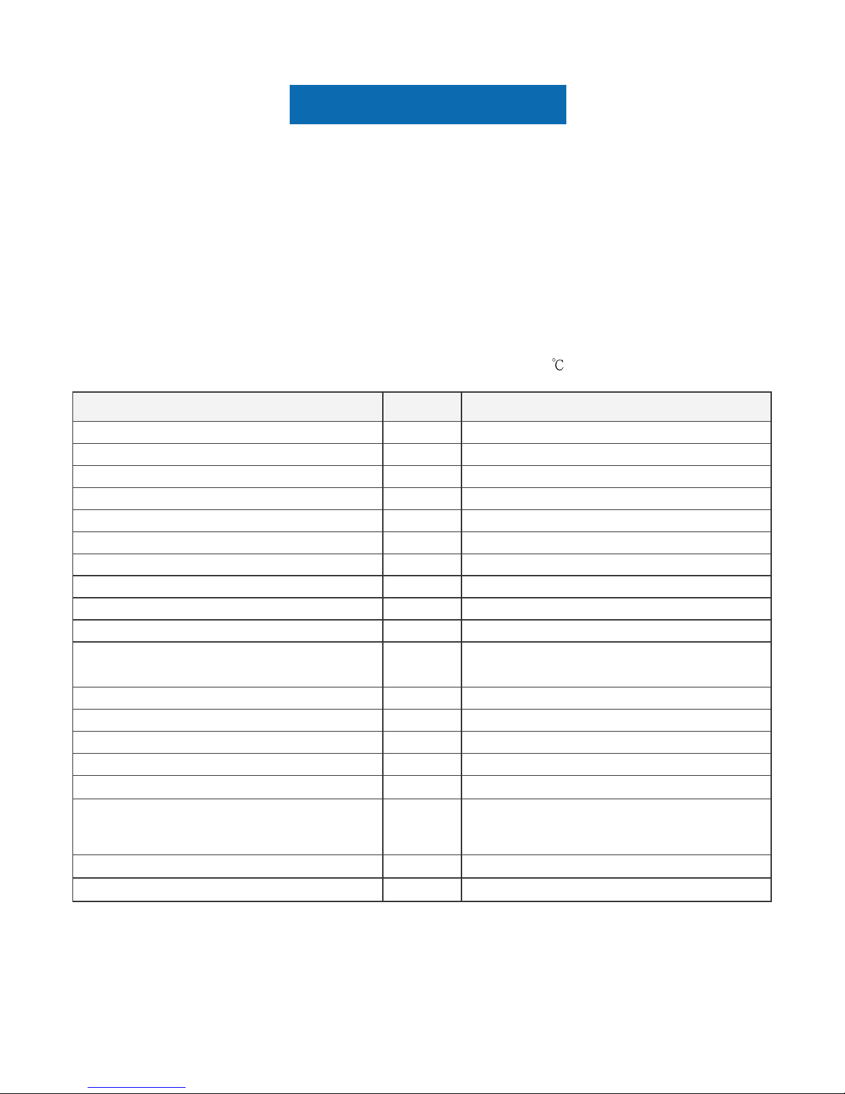
2.1 Display Characteristics
The following items are characteristics summary on the table under 25 condition:
Items Unit Specifications
Screen Diagonal [mm] 482.6 (19.0" )
Active Area [mm] 376.32 (H) x 301.06 (V)
Pixels H x V 1280(x3) x 1024
Pixel Pitch [mm] 0.294 (per one triad) x 0.294
epirtS lacitreV .B.G.R tnemegnarrA lexiP
Display Mode Normally White
m/dc[ ecnanimuL etihW
2
] 250 (center, Typ) @60.0mA
Contrast Ratio 1000 : 1 (Typ)
)ffo/no ,pyT(sm 5 ]cesm[ emiTesnopseR lacitpO
V 0.5+ ]tloV[ DDV egatloV tupnI lanimoN
]ttaW[ noitpmusnoC rewoP
15.2 W (Typ)
(PDD= 4.6 W, PLED=10.6 W )
Weight [Grams] 1800 (Typ)
01 x )V( 423 x )H( 693 ]mm[ )D x V x H( eziS lacisyhP .9(D) (Typ)
SDVL lennahc lauD ecafretnI lacirtcelE
taert eralG-noN ,)H3( gnitaoc-draH tnemtaerT ecafruS ment
Support Color 16.7M colors (RGB 6-bit + Hi_FRC)
Temperature Range
Operating
Storage (Non-Operating)
[oC]
[
o
C]
0 to +50
-20 to +60
ecnailpmoC SHoR ecnailpmoC SHoR
ecnailpmoC 1.5 OCT ecnailpmoC OCT
Panel Specification
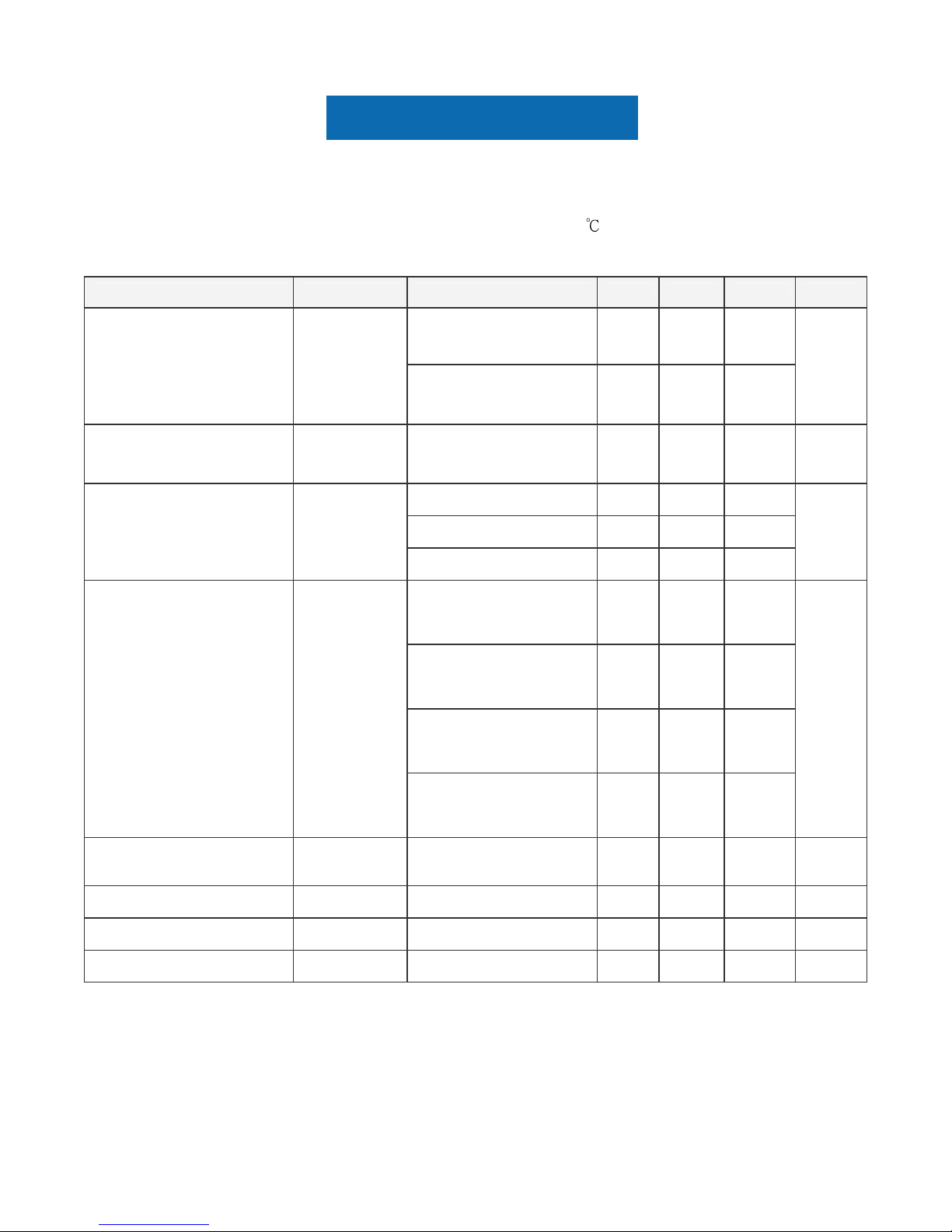
2.2 Optical Characteristics
The optical characteristics are measured under stable conditions at 25 (Room Temperature):
Item Unit Conditions Min. Typ. Max. Note
Horizontal (Right)
CR = 10 (Left)
75
75
85
85
-
Viewing Angle [degree]
Vertical (Up)
CR = 10 (Down)
70
70
80
80
-
2
3 - 0001 006 noitceriD lamroN oitaR tsartnoC
Raising Time (TrR)
- 3.6 5.7
Falling Time (TrF)
- 1.4 2.3
Optical Response Time [msec]
Rising + Falling - 5 8
4
906.0 x deR
0.639 0.669
613.0 y deR
0.346 0.376
Green x 0.294 0.324 0.354
Green y 0.597 0.627 0.657
421.0 x eulB
0.154 0.184
420.0 y eulB
0.054 0.084
White x 0.283 0.313 0.343
Color / Chromaticity
Coordinates
(CIE)
White y 0.299
0.329 0.359
5
Central Luminance
[cd/m
2
6 - 052 002 ]
7 - 08 57 stnioP 9 ]%[ ytimrofinU ecnanimuL
8 5.1 - - ]%[ )zH06 tA( klaT ssorC
02- - - ]Bd[ rekcilF
9
Panel Specification
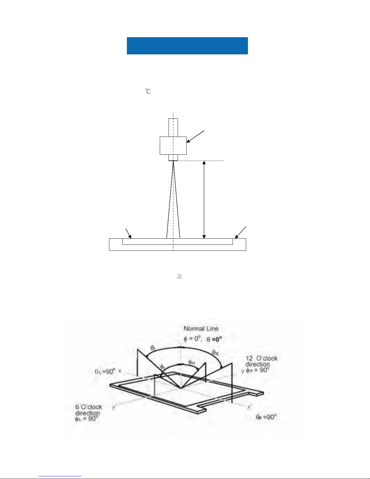
Note 1: Measurement method
The LCD module should be stabilized at given temperature for 30 minutes to avoid abrupt temperature
change during measuring (at surface 35
). In order to stabilize the luminance, the measurement should be
executed after lighting Backlight for 30 minutes in a stable, windless and dark room.
Note 2: Definition of viewing angle measured by ELDIM (EZContrast 88)
Viewing angle is the measurement of contrast ratio
10, at the screen center, over a 180° horizontal and
180° vertical range (off-normal viewing angles). The 180° viewing angle range is broken down as follows;
90° (θ) horizontal left and right and 90° (Φ) vertical, high (up) and low (down). The measurement direction is
typically perpendicular to the display surface with the screen rotated about its center to develop the desired
measurement viewing angle.
Center of the screen
TFT-LCD
Measured distance
Photo detector
LCD Panel
Panel Specification
Note 3: Contrast ratio is measured by TOPCON SR-3
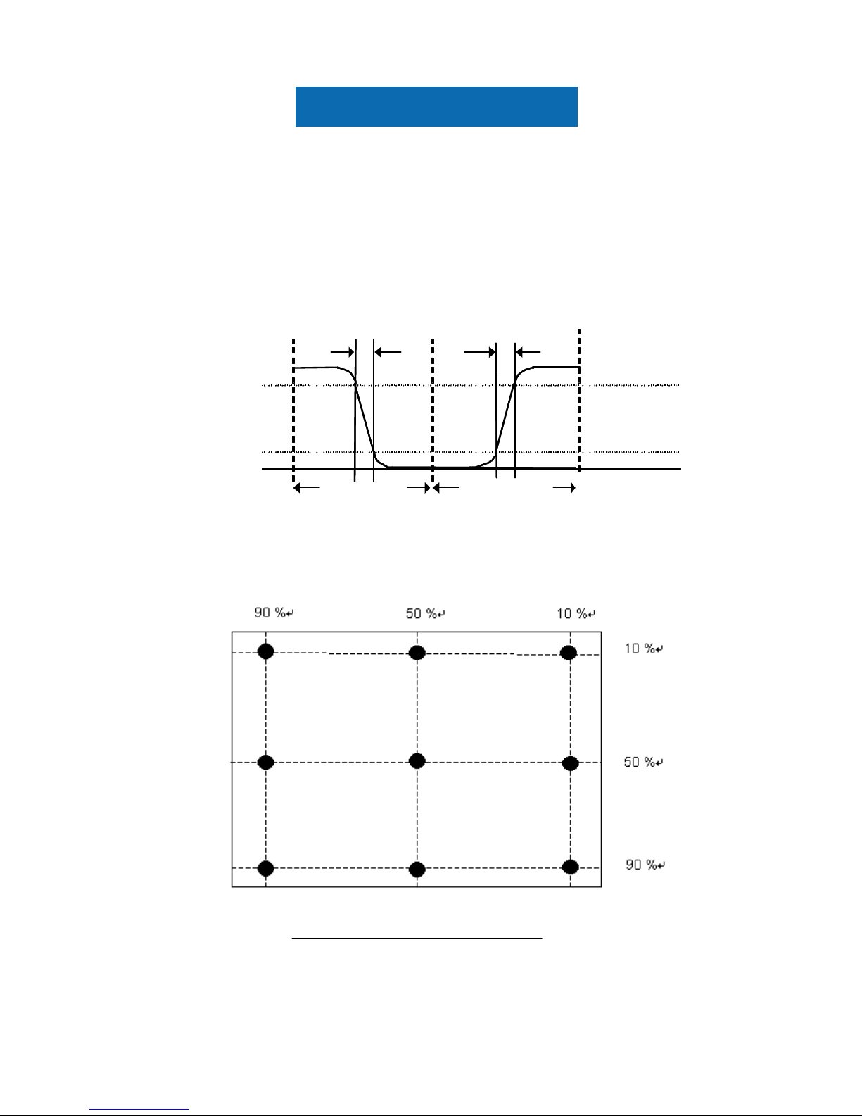
Note 4: Definition of Response time measured by Westar TRD-100A
The output signals of photo detector are measured when the input signals are changed from “Full
Black” to “Full White” (rising time, T
rR
), and from “Full White” to “Full Black” (falling time, TrF),
respectively. The response time is interval between the 10% and 90% (1 frame at 60 Hz) of
amplitudes.
T
rR
+ TrF = 5 msec (typ.).
N
ote 5: Color chromaticity and coordinates (CIE) is measured by TOPCON SR-3
Note 6: Central luminance is measured by TOPCON SR-3
Note 7: Luminance uniformity of these 9 points is defined as below and measured by TOPCON SR-3
9)-(1 Points 9in LuminanceMaximum
9)-(1 points 9in LuminanceMinimum
Uniformity =
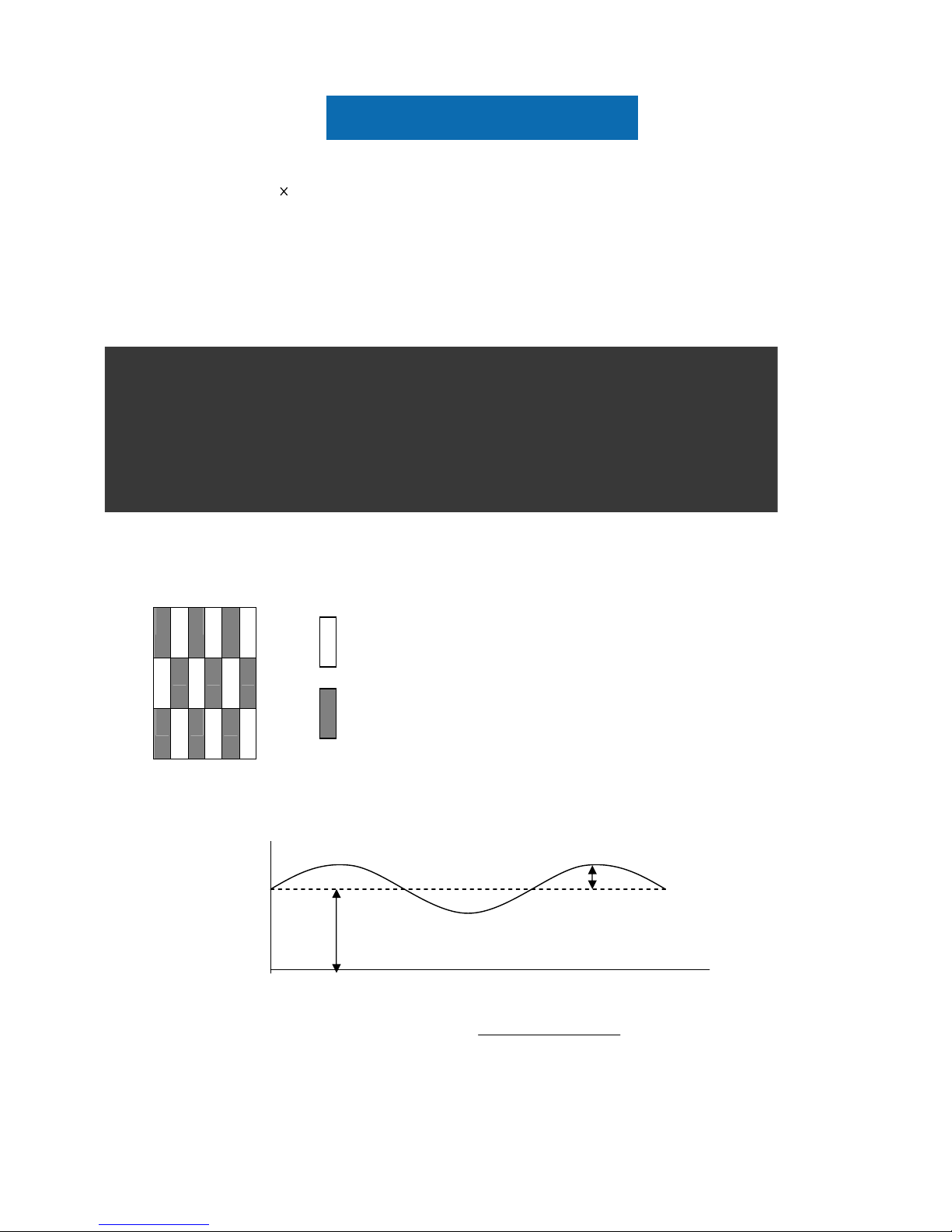
Note 8: Crosstalk is defined as below and measured by TOPCON SR-3
100
90
10
0
%
Optical
response
White
T
rF
100 10
0
%
Optical
response
White
Black
Black
1 Frame
1 Frame
T
rR
Panel Specification
CT = | YB – YA | / YA 100 (%)
Where
YA = Luminance of measured location without gray level 0 pattern (cd/m2)
YB = Luminance of measured location with gray level 0 pattern (cd/m2)
Note 9: Test Patern: Subchecker Pattern measured by TOPCON SR-3
R G B R G B
R G B R G B
R G B R G B
Method: Record dBV & DC value with TRD-100
Level
DC
Hz) 30Level(at AC
log20(dB)Flicker =
Amplitude
Time
DC
AC
Gray Level = L127
Gray Level = L0
Panel Specification
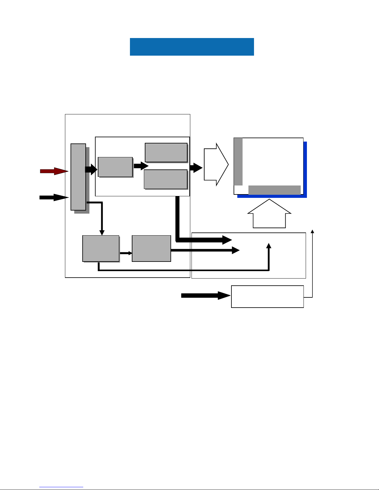
3. Functional Block Diagram
The following diagram shows the functional block of the 19.0 i nch C olor TFT-LCD Module:
I/F PCB Interface:
187034-30091 / FI-XB30SSLA-HF15
Mating Type:
FI-X30HL (Locked Type)
FI-X30H (Unlocked Type)
TFT-LCD
1280*(3)*1024
Pixels
G1024
D1
LED
Backlight
LED Driver on system
Gamma
Correction
LVD
S
+5V
G1
D3840
Connector
LVDS
Receiver
Timing
Controller
ASIC
Mini-LVDS
Transmitter
DC/DC
Converter
 Loading...