

winsonic MFC1705S-EN30C User Manual

User’s Manua
- Model #0)&6(1&
WINSONIC ELECTRONICS Co., LTD
No.290-1, Wen Chung Rd., Taoyuan City, Taiwan, R.O.C
l:+886-3-3704789
ax:+886-3-3704722
E-mail:sales@ewinsonic.com
www.ewinsonic.com
Te
F

AD Board Specification
Panel Specification
Safety Instruction
Product Installation
Contents
General Description
Absolute Maximum Ratings
Precautions
Assembly
Trouble Shooting
3
4
5
33
5
6
Electrical Specifications
13
Optical Specifications
7
30
40
41
Safety Instruction
Read and follow these instructions when connecting and using your LCD monitor:
Operation:
1. Keep the monitor out of direct sunlight and away from stoves or any other heat
source.
2. Remove any object that could fall into ventilation holes or prevent proper cooling
of the monitor's electronics.
3. Do not block the ventilation holes on the cabinet.
4. When positioning the monitor, make sure the power plug and outlet are easily
accessible.
5. If turning off the monitor by detaching the power cable or DC power cord, wait
for seconds before attaching the power cable or DC power cord for normal
operation.
6. Do not subject the LCD monitor to severe vibration or high impact conditions
during operation.
7. Do not knock or drop the monitor during operation or transportation.
Maintenance:
8. To protect your display from possible damage, do not put excessive pressure on
the LCD panel. When moving your monitor, grasp the frame to lift; do not lift the
monitor by placing your hand or fingers on the LCD panel.
9. Unplug the monitor if you are not going to use it for an extensive period of time.
10. Unplug the monitor if you need to clean it with a slightly damp cloth. The screen
may be wiped with a dry cloth when the power is off. However, never use organic
solvent, such as, alcohol, or ammonia-based liquids to clean your monitor.
11. To avoid the risk of shock or permanent damage to the set, do not expose the
monitor to dust, rain, water, or excessive moisture environment.
12. If y
our monitor gets wet, wipe it with dr
y cloth as soon as possible.
13. If foreign substance or water gets in your monitor, please turn the power off
immediately and disconnect the power cord. Then, remove the foreign substance
or water, and send it to the maintenance center.
14. Do not store or use the LCD monitor in locations exposed to heat, direct sunlight
or extreme cold.
15. In order to maintain the best performance of your monitor and use it for a longer
lifetime, please use the monitor in a location that falls within the following
temperature and humidity ranges. Temperature: 5-35°C 41-95°F

Product Installation
1. Switch off the power on both your monitor and your computer. The Power Switch
is located in the right of the monitor.
2. Connect the power cord to the AC outlet, and connect the power to the monitor
through the AC/DC adapter.
3. VGA Signal-Plug one end of the 15-pin signal cable to the video signal connector
at the rear of the PC system and the other end to the monitor. Secure the
connectors with the screws on the cable connector at both ends.
4. (Optional) DVI Signal-Plug one end of the DVI signal cable to the video signal
connector at the rear of the PC system and the other end to the monitor. Secure
the connectors with the screws on the cable connector at both ends.
5. (Optional) HDMI Signal-Plug one end of the HDMI signal cable to the video
signal connector at the rear of the PC system and the other end to the monitor.
Secure the connectors with the screws on the cable connector at both ends.
6. (Optional) RS232 Connection- Plug one end of RS232 cable to com-port
connector on your PC system and the other end to the monitor. Secure the
connectors with the screws on the cable connector at both ends.
Panel Specification
MFC1705S-EN30C is a color active matrix liquid crystal display (LCD) that uses amorphous
silicon TFT (Thin Film Transistor) as switching components. This model is composed of
a TFT LCD panel, a driver circuit and a back light unit. The resolution of a 17.0” is 1280
x 1024 and this model can display up to 16.7 millions colors.
Workstation & desktop monitors
Display terminals for AV application products
Monitors for industrial machine
* If the module is used to other applications besides the above, please contact SEC
in advance.
Features
General Description
Description
Applications
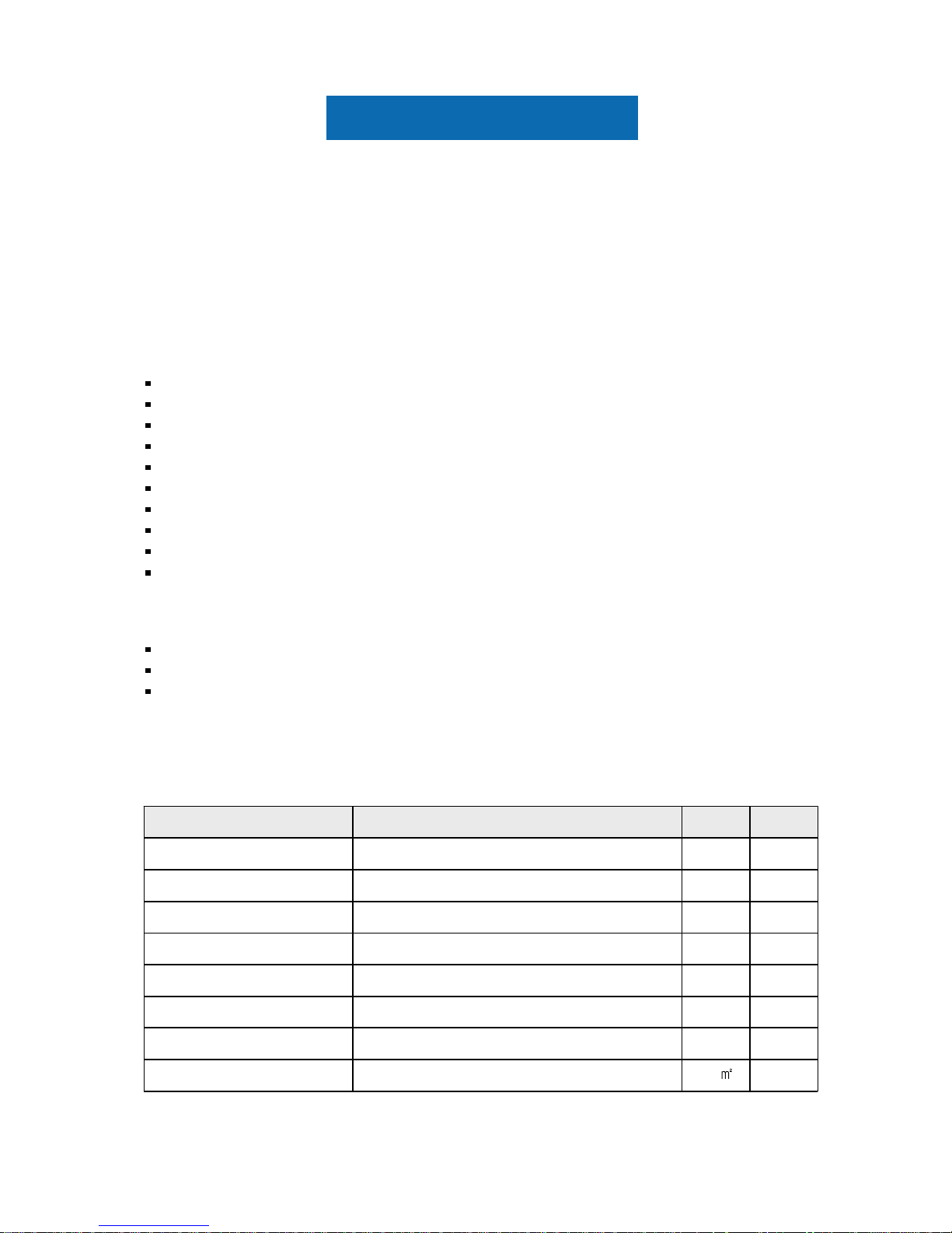
General Information
mm0.264(H) x 0.264(W)Pixel Pitch
mm337.92(H) x 270.336(V)Active Display Area
Note
Haze 25, Hard-Coating (3H)Surface Treatment
cd/
300(Typ.)Luminance of White
Normally WhiteDisplay Mode
RGB vertical stripePixel Arrangement
pixel1,280 x 1,024Number of Pixels
colors16.7M (Hi-FRC)Display Colors
UnitSpecificationItems
High contrast ratio, high aperture structure
TN (Twisted Nematic) mode
Wide Viewing Angle
High speed response
SXGA (1280 x 1024 pixels) resolution
Low power consumption
DE (Data Enable) only mode
LVDS (Low Voltage Differential Signaling) interface (2pixel/clock)
Compact Size Design
RoHS compliance
Panel Specification
Note (1) Mechanical tolerance is 0.5mm unless there is a special comment.
Mechanical Information
1700
13.3
290.8
355.4
Max.
LCD module onlyg--Weight
mm--Depth (D)
mm290.3289.8Vertical (V)
mm354.9354.4Horizontal (H)
Module
size
NoteUnitTyp.Min.Item
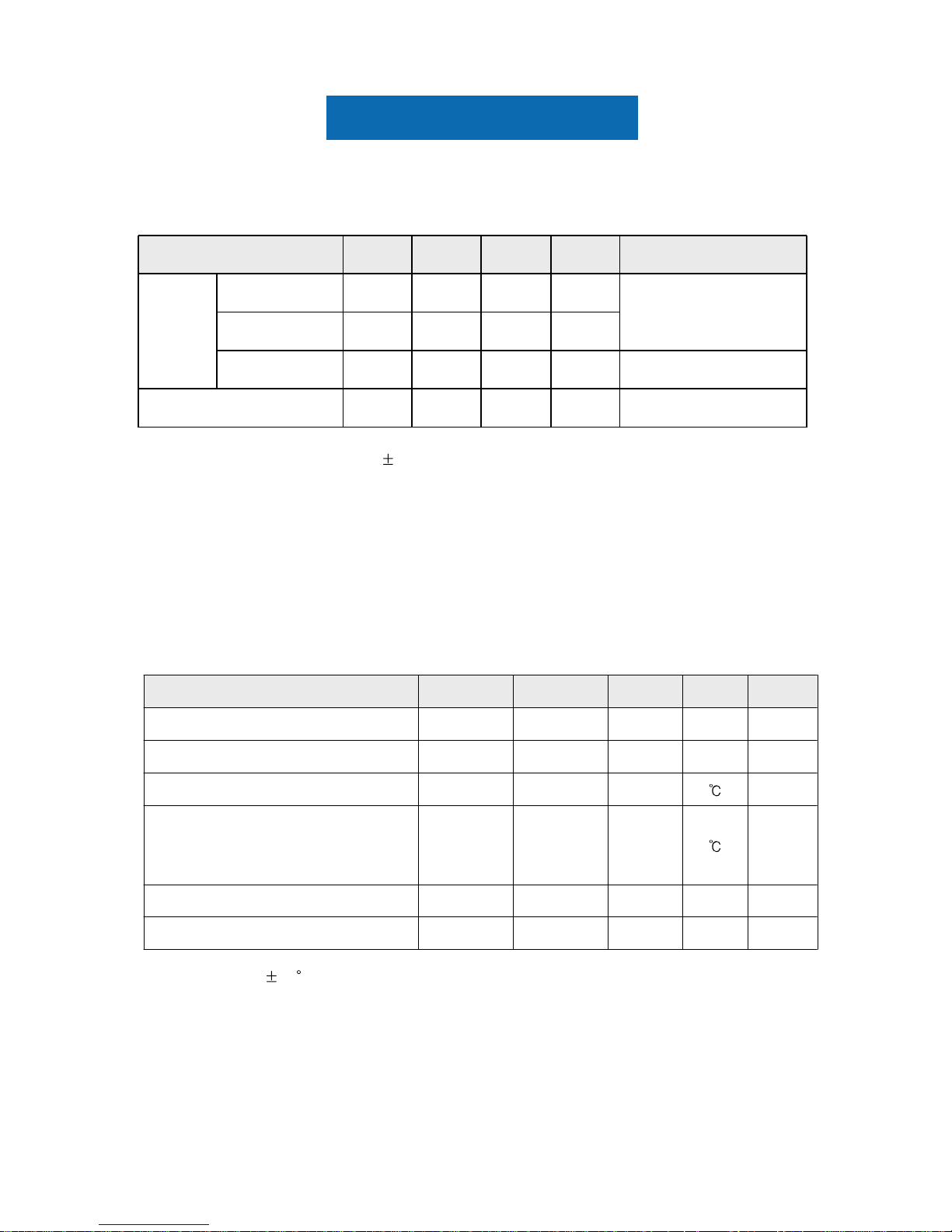
1. Absolute Maximum Ratings
If the condition exceeds maximum ratings, it can cause malfunction or unrecoverable
damage to the device.
Note (1) Ta= 25 2 C
V6.5GND-0.5V
DD
Power Supply Voltage
V5-V
sig
Data Signal
(3)G1.5-V
nop
Vibration ( non - operating )
(2)G50-S
nop
Shock ( non - operating )
500T
OPR
Glass surface temperature
(Operation)
(1)
60-25T
STG
Storage temperature
NoteUnitMax.Min.SymbolItem

Panel Specification
(1) Temperature and relative humidity range are shown in the figure below.
a. 90 % RH Max. (Ta
39 C)
b. Maximum wet-bulb temperature at 39
C or less. (Ta 39 C)
c. No condensation
(2) 11ms, sine wave, one time for
X, Y, Z axis
(3) 10-300 Hz, Sweep rate 10min, 30min for X,Y,Z axis
Fig. Temperature and Relative humidity range
(39,90)
(39,90)
(60,27.7)
(60,27.7)
(50,50.4)
(50,50.4)
((--25,5)
25,5)
(39,90)
(39,90)
(60,27.7)
(60,27.7)
(50,50.4)
(50,50.4)
((--25,5)
25,5)
Panel Specification
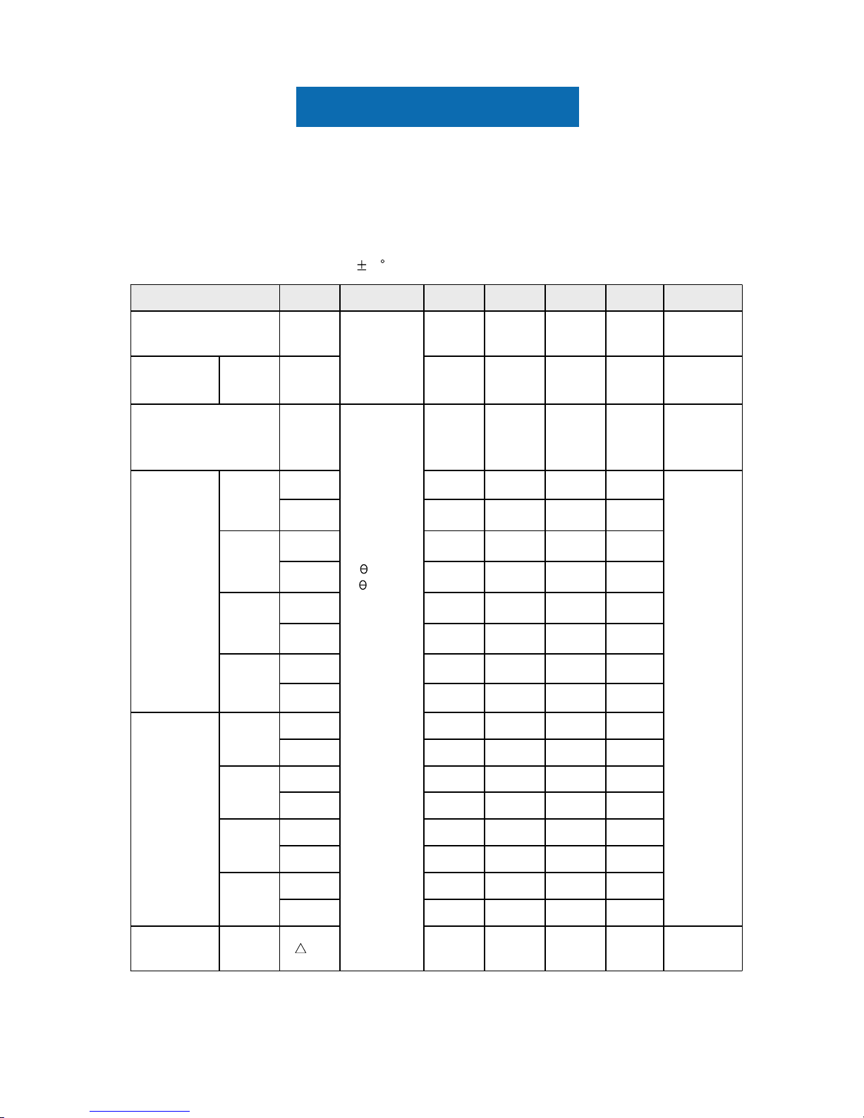
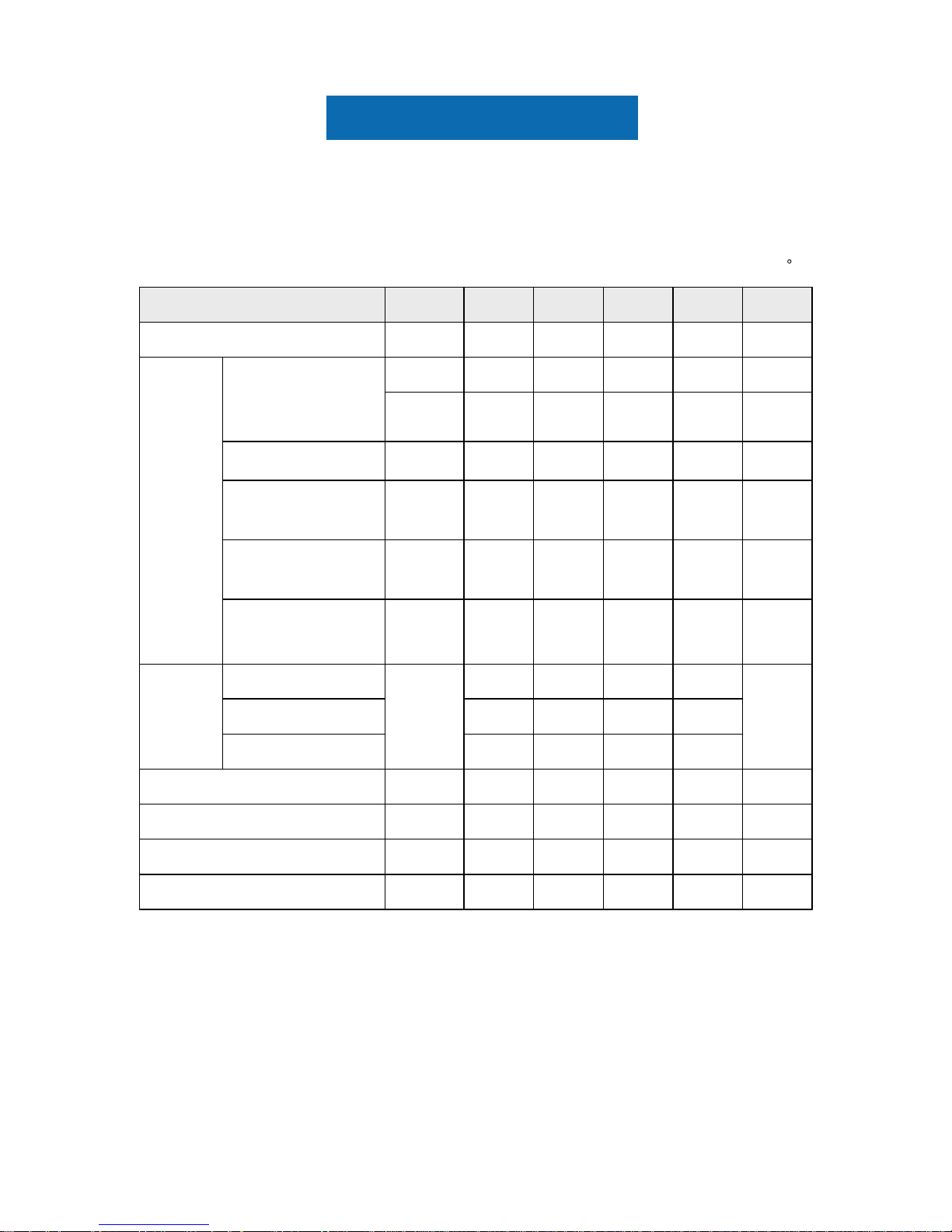
2. Optical Characteristics
* C.G.L : Color Grayscale Linearity )egap txen eht ot eunitnoc(
(7),(8)
PR650
(6)
BM-5A
cd/m2-300250Y
L
Luminance of White
(Center of screen)
(5)
RD-80S
(10)5-Tr + TfOn/Off
Response
Time
msec
Normal
L,R
=0
U,D
=0
Viewing
Angle
(9)0.02--
u'v'White
C.G.L
(ACC ONLY)
-0.468-Wv'
-0.198-Wu'
White
-0.197-Bv'
-0.174-Bu'
Blue
-0.563-Gv'
-0.125-Gu'
Green
-0.525-Rv'
-0.459-Ru'
Red
Color
Chromaticity
(CIE 1976)
0.3590.3290.299Wy
0.3430.3130.283Wx
White
0.1100.0800.050By
0.1800.1500.120Bx
Blue
0.6300.6000.570Gy
0.3300.3000.270Gx
Green
0.3600.3300.300Ry
0.6800.6500.620Rx
Red
Color
Chromaticity
(CIE 1931)
(3)
BM-5A
---C/R
Contrast Ratio
(Center of screen)
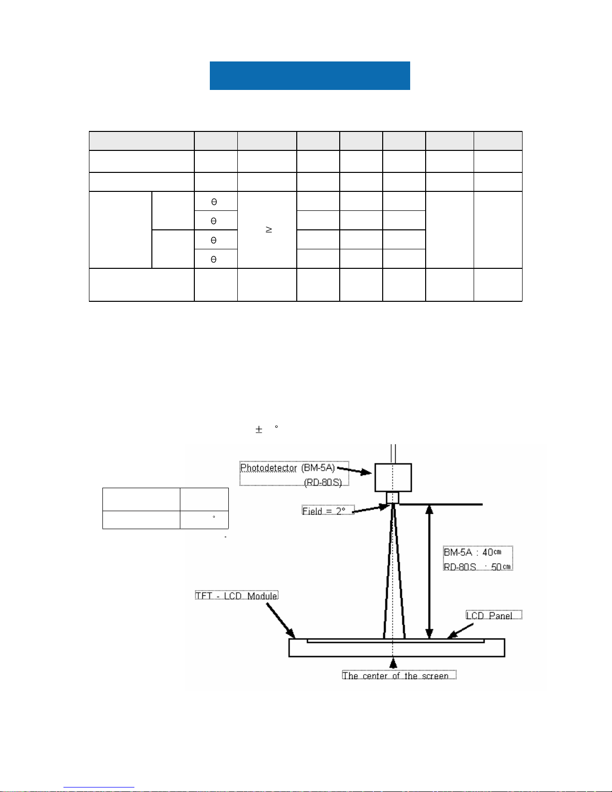
NoteUnitMax.Typ.Min.ConditionSymbolItem
The optical characteristics should be measured in a dark room or equivalent.
Measuring equipment : TOPCON RD-80S, BM-5A
Photo Research PR650
(Ta = 25 2 C, VDD=5V, fv= 60Hz, fDCLK=54MHz, IL = 6.5mArms
Panel Specification
(4)
BM-5A
%25--B
uni
Brightness Uniformity
(9 Points)
K-6500--Color Temperature
%-72--Color Gamut
NoteUnitMax.Typ.Min.ConditionSymbolItem
-80-
D
-80-
U
Ver.
-80-
R
(8)
BM-5A
Degrees
-80-
CR
10
L
Hor.
Viewing
Angle
Note (1) Test Equipment Setup
The measurement should be executed in a stable, windless and dark room between
30min after lighting the back light at the given temperature for stabilization
of the back light. This should be measured in the center of screen.
Single lamp current : 6.5mA
Environment condition : Ta = 25
2 C
2BM-5A
Field Photo detector
Panel Specification
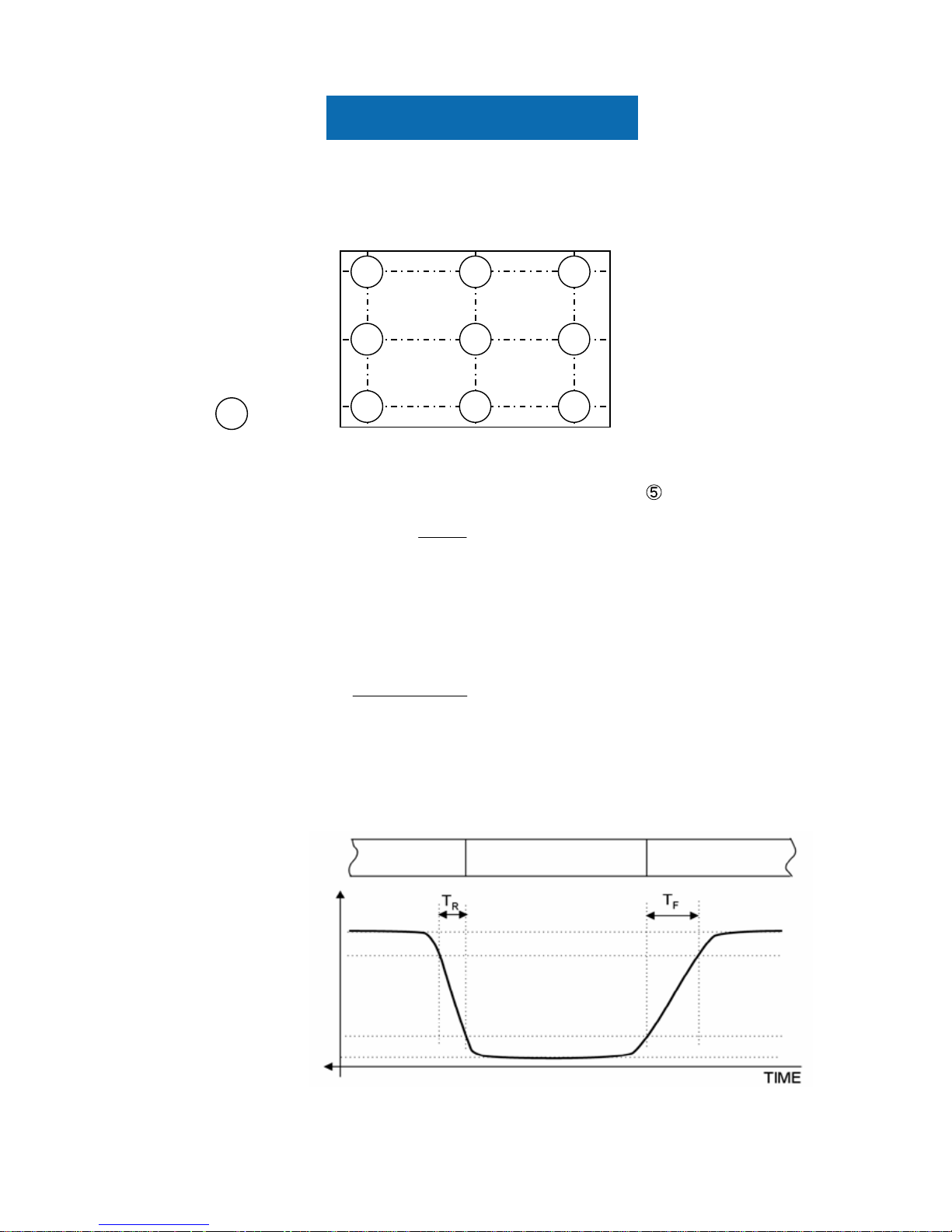
Note (2) Definition of test point
Note (3) Definition of Contrast Ratio (C/R)
: Ratio of gray max (Gmax) & gray min (Gmin) at the center point
of the panel
Note (4) Definition of 9 points brightness uniformity
Note (5) Definition of Response time : Sum of Tr, Tf
Buni
B B
B
= ×
−
100
( max min)
max
Bmax : Maximum brightness
Bmin : Minimum brightness
CR
G
G
=
max
min
Gmax : Luminance with all pixels white
Gmin : Luminance with all pixels black
100%
90%
10%
0%
Optical Instruments
Response
Display Data White(TFT off) Black(TFT on) White(TFT off)
6
8 79
3 2 1
45
128 640 1152
102
512
922
Active Area
: Test Point

Panel Specification
Note (6) Definition of Luminance of White : Luminance of white at center point
Note (7) Definition of Color Chromaticity (CIE 1931, CIE1976)
Color coordinate of Red, Green, Blue & White at center point
Note (8) Definition of Viewing Angle
: Viewing angle range (CR
10)
Panel Specification
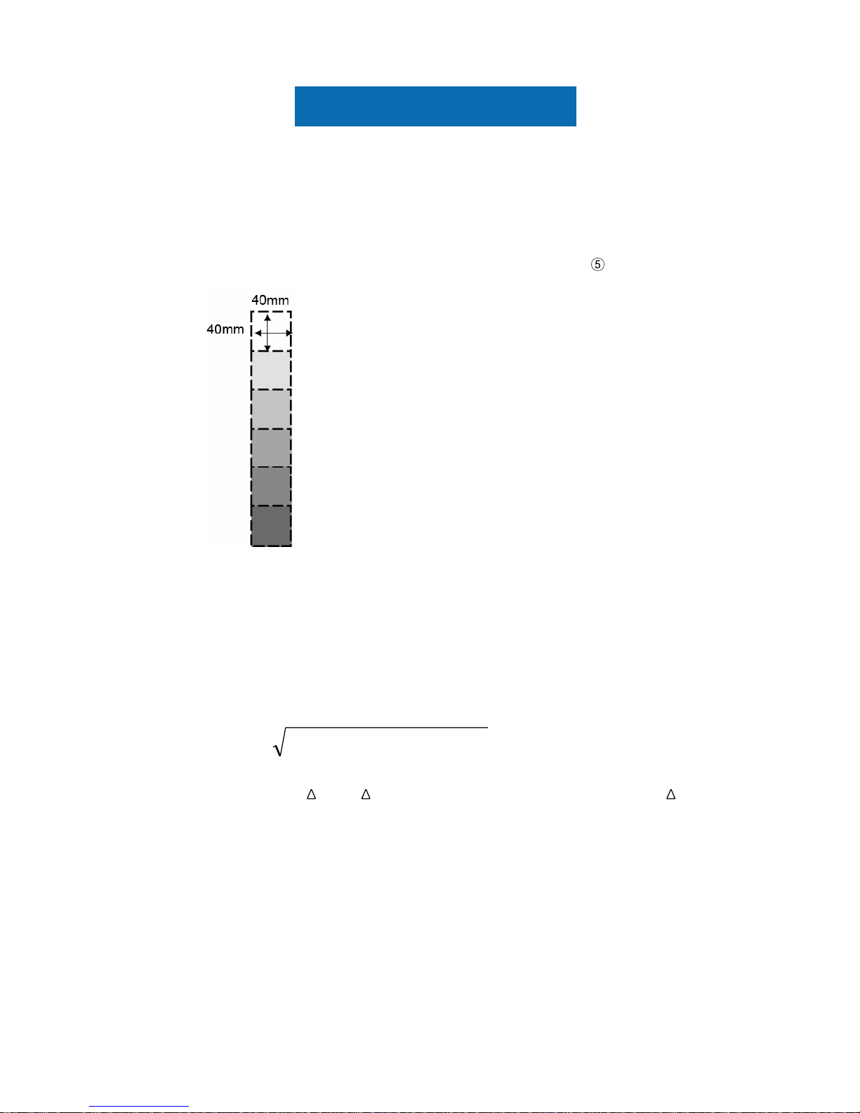
Note (9) Color Grayscale Linearity.
a. Test image : 100% full white pattern with a test pattern as below
b. Test pattern : Squares, 40mm by 40mm in size, filled with 255, 225, 195, 165, 135 and
105 grays steps should be arranged at the center
of the screen.
c. Test method
-1
st
gray step : move a square of 255 gray level should be moved into the center of
the screen and measure luminance and u’ and v’ coordinates.
- Next gray step : Move a 225 gray square into the center and measure both
luminance and coordinates, too.
d. Test evaluation
Where A, B : 2 gray levels found to have the largest color differences between them
i.e. get the largest
u’ and v’ of each 6 pair of u’ and v’ and calculate the u’v’.
∆u'v'= (u' -u' ) +(v' -v' )A B
2
A B
2
Panel Specification
3.1 TFT LCD Module
The connector for display data & timing signal should be connected (GND=0V)
Ta = 25
C
Note (1) The ripple voltage should be controlled under 10% of V
DD
.
3. Electrical Characteristics
Common mode
voltage
Input voltage range
(single-ended)
Differential input
voltage
LVDS skew
Differential Input
Voltage for LVDS
Receiver Threshold
(4)V2.40V
IN
(4)V
2.4-
|V
ID
|/2
1.2
0+
|VID|/2
V
CM
(4)mV600200|VID|
(3)300-300t
SKEW
(7)A3.0--I
RUSH
Rush Current
MHz67.55445f
DCLK
Main Frequency
kHz79.9766453f
H
Hsync Frequency
Hz756050f
V
Vsync Frequency
mA(800)(700)-(c) Dot
mA-(500)- )6(,)5(etihW )b(
mA-(600)-
I
DD
(a) Black
Current of
Power
Supply
mV---100Low
(2)mV+100--High
LVDS
Input
Characteri
stics
(1)V5.55.04.5V
DD
Voltage of Power Supply
NoteUnitMax.Typ.Min.SymbolItem
 Loading...