

winsonic MFC1045S-SN35C User Manual
User’s Manua
- Model #MFC1045S-SN35C
WINSONIC ELECTRONICS Co., LTD
No.290-1, Wen Chung Rd., Taoyuan City, Taiwan, R.O.C
l:+886-3-3704789
ax:+886-3-3704722
E-mail:sales@ewinsonic.com
www.ewinsonic.com
Te
F

AD Board Specification
Panel Specification
Safety Instruction
Product Installation
Contents
General Description
Optical Specifications
Absolute Maximum Ratings
Electrical Specifications
Precautions
Assembly
Trouble Shooting
3
4
5
22
5
6
11
8
21
30
31
Safety Instruction
Read and follow these instructions when connecting and using your LCD monitor:
Operation:
1. Keep the monitor out of direct sunlight and away from stoves or any other heat
source.
2. Remove any object that could fall into ventilation holes or prevent proper cooling
of the monitor's electronics.
3. Do not block the ventilation holes on the cabinet.
4. When positioning the monitor, make sure the power plug and outlet are easily
accessible.
5. If turning off the monitor by detaching the power cable or DC power cord, wait
for seconds before attaching the power cable or DC power cord for normal
operation.
6. Do not subject the LCD monitor to severe vibration or high impact conditions
during operation.
7. Do not knock or drop the monitor during operation or transportation.
Maintenance:
8. To protect your display from possible damage, do not put excessive pressure on
the LCD panel. When moving your monitor, grasp the frame to lift; do not lift the
monitor by placing your hand or fingers on the LCD panel.
9. Unplug the monitor if you are not going to use it for an extensive period of time.
10. Unplug the monitor if you need to clean it with a slightly damp cloth. The screen
may be wiped with a dry cloth when the power is off. However, never use organic
solvent, such as, alcohol, or ammonia-based liquids to clean your monitor.
11. To avoid the risk of shock or permanent damage to the set, do not expose the
monitor to dust, rain, water, or excessive moisture environment.
12. If y
our monitor gets wet, wipe it with dr
y cloth as soon as possible.
13. If foreign substance or water gets in your monitor, please turn the power off
immediately and disconnect the power cord. Then, remove the foreign substance
or water, and send it to the maintenance center.
14. Do not store or use the LCD monitor in locations exposed to heat, direct sunlight
or extreme cold.
15. In order to maintain the best performance of your monitor and use it for a longer
lifetime, please use the monitor in a location that falls within the following
temperature and humidity ranges. Temperature: 5-35°C 41-95°F

Product Installation
1. Switch off the power on both your monitor and your computer. The Power Switch
is located in the right of the monitor.
2. Connect the power cord to the AC outlet, and connect the power to the monitor
through the AC/DC adapter.
3. VGA Signal-Plug one end of the 15-pin signal cable to the video signal connector
at the rear of the PC system and the other end to the monitor. Secure the
connectors with the screws on the cable connector at both ends.
4. (Optional) DVI Signal-Plug one end of the DVI signal cable to the video signal
connector at the rear of the PC system and the other end to the monitor. Secure
the connectors with the screws on the cable connector at both ends.
5. (Optional) HDMI Signal-Plug one end of the HDMI signal cable to the video
signal connector at the rear of the PC system and the other end to the monitor.
Secure the connectors with the screws on the cable connector at both ends.
6. (Optional) RS232 Connection- Plug one end of RS232 cable to com-port
connector on your PC system and the other end to the monitor. Secure the
connectors with the screws on the cable connector at both ends.
Panel Specification
GENERAL DESCRIPTION
DESCRIPTION
MFC1045S-SN35C is a color active matrix TFT (Thin Film Transistor) liquid crystal display (LCD)
that uses amorphous silicon TFT as a switching devices. This model is composed of a TFT
LCD panel, a driver circuit and a back-light system. The resolution of a 10.4 〃contains
800 x 600 pixels and can display up to 262,144colors. 6 o'clock direction is the optimum
viewing angle.
FEATURES
• Thin and light weight
• High speed response time
• High contrast ratio, High brightness
• SVGA (800 x 600 pixels) resolution
• Low power consumption
•LVDS Interface with 1 pixel / clock (1 channel)
APPLICATIONS
• Display terminals for AV application products
• Notebook PC, LCD PC and Web Pad
• If the usage of this product is not for PC application, but for others, please contact SEC.
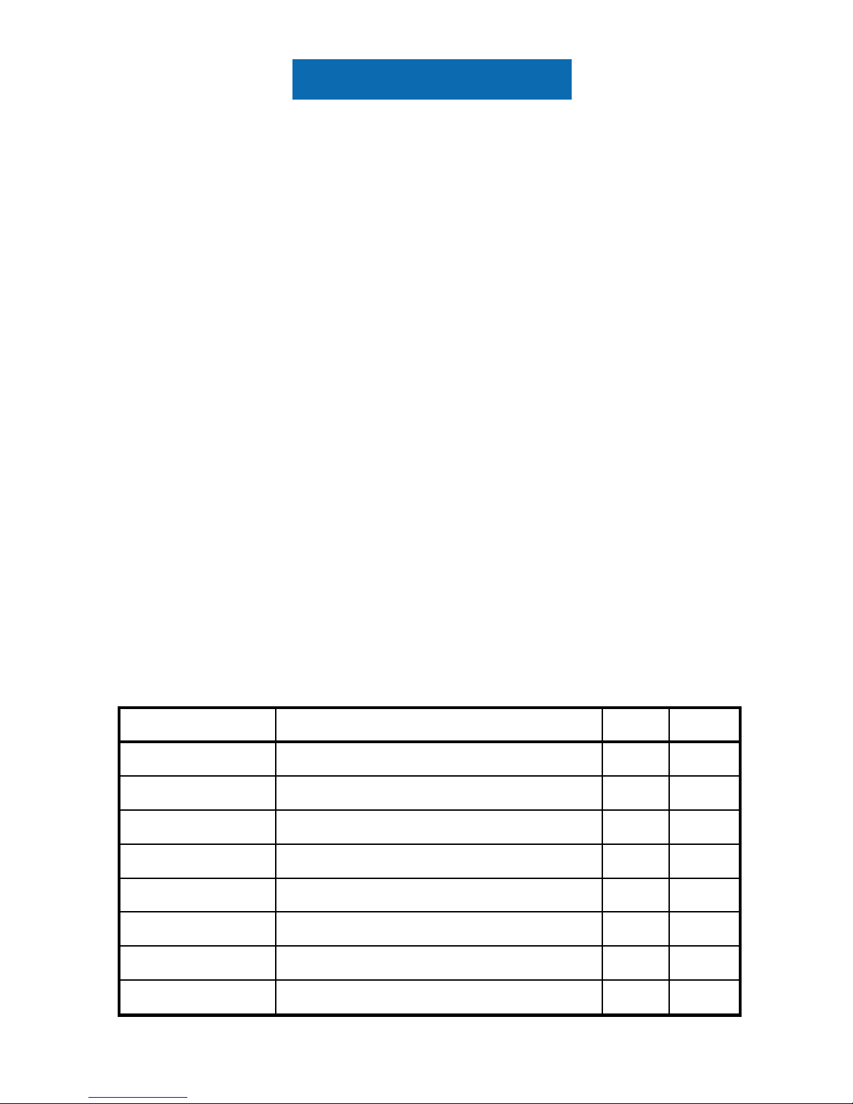
GENERAL INFORMATION
Display area
211.2(H) x 158.4(V) (10.4〃diagonal )
Pixel arrangement RGB vertical stripe
NOITACIFICEPSMETI
mm
pixel
Pixel pitch 0.264(H) x 0.264(V) (TYP.)
UNIT
Normally white
Display Mode
Display colors 262,144
NOTE
Surface treatment
Haze (25), Hard-Coating 3H
Driver element a-Si TFT active matrix
Number of pixel 800 x 600 x RGB (SVGA)
mm
96dpi
Panel Specification
1. ABSOLUTE MAXIMUM RATINGS
1.1 ABSOLUTE RATINGS OF ENVIRONMENT
MECHANICAL INFORMATION
ETON.XAM.PYTMETI
Module
size
Weight
226.0 226.5
177.8
MIN.
178.3177.3
Horizontal (H)
Vertical (V)
Depth (D) -
225.5
- 10.5
- 495 -
Note (1) Temperature and relative humidity range are shown in the figure below.
90 % RH Max. ( 40 °C Ta)
Maximum wet - bulb temperature at 39 °C or less. (Ta > 40°C ) No condensation.
(2) 11ms, (half) sine wave, one time for ± X, ± Y, ± Z.
(3) (5) - (500) Hz, Sweep rate (1) hr, (3)hr for X,Y,Z.
(4) At testing Vibration and Shock, the fixture in holding the Module to be tested have to be
hard and rigid enough so that the Module would not be twisted or bent by the fixture.
0
20
40
60
80
100
-40 -20 0 20 40 60 80
5
90
Operating Range
Storage Range
Relative Humidity ( %RH)
Temperature (OC)
ETONTINUMETI
Operating temperature
(Temperature of glass surface)
SYMBOL MIN. MAX.
T
STG
T
OPR
0
50
Storage temperature
-20 60
°C
°C
Vibration (non-operating)
Shock ( non-operating )
Snop
Vnop
-
1.0
-
50 G
G
(1)
(1)
(2),(4)
(3),(4)
Panel Specification
NOTE (1) Permanent damage to the device may occur if maximum values are exceeded.
Functional operation should be restricted to the conditions described under Normal Operating
Conditions.
(2) BACK-LIGHT UNIT
Ta = 25 ± 2 °C
ITEM
SYMBOL
Lamp current
I
L
MIN.
UNIT. NOTE
3.0
mA
rms
MAX.
(1)
Lamp frequency
F
L
40
7.0
80
KHz
(1)
1.2 ELECTRICAL ABSOLUTE RATINGS
(1) TFT LCD MODULE
( Vss = GND = 0 V)
NOTE (1) Within Ta = 25 ± 2 °C
ITEM
SYMBOL
MIN. MAX. UNIT NOTE
Power Supply Voltage V
DD
Logic Input Voltage V
IN
Vss -0.3
Vss -0.3
V
VV
DD+0.3
( 1 )
( 1 )
4.0

Panel Specification
2. OPTICAL CHARACTERISTICS
The following items are measured under stable conditions. The optical characteristics
should be measured in a dark room or equivalent state with the methods shown in Note
(5).
Measuring equipment : TOPCON BM-5A
* Ta = 25 ± 2°C , VDD=3.3V, fv= 60Hz, fDCLK=40MHz, IL = 6.0 mA
Response
Time at Ta
R
X
msec
(1), (2), (5)
(1), (3)
Color
Chromaticity
( CIE )
Red
Green
Blue
White
R
Y
GX
GY
BX
BY
WX
WY
(1), (5)
Viewing
Angle
Hor.
Ver.
θ
L
φH
θR
φL
φ= 0,
θ= 0
Average Luminance
of White (5 Points)
Normal
Viewing
Angle
ITEM SYMBOL CONDITION MIN. TYP. MAX. UNIT
Contrast Ratio
(5 Points)
CR
Rising
T
R
Falling
T
F
-
-
-
CR 10
at center
-
cd/m
2
YL,AVE
Degrees
NOTE
(1), (4)
150
350280
-
-
-
-
0.343
0.616
0.368
0.169
0.557
0.182
0.586
0.338
0.313
0.527
0.152
0.139
0.313
0.327 0.357
0.343
0.556
0.308
0.283
0.497
0.122
0.103
0.283
0.297
10
30
20
50
50
50
35
35
-
-
-
-
Panel Specification
Note 3) Definition of Response time :
Note 1) Definition of Viewing Angle : Viewing angle range(10 C/R)
Note 4) Definition of Average Luminance of White : measure the luminance of white at center point @
: test point
VIEW AREA
150
300
450
lines
200 400 600
3
2
1
4
5
6 O’clock
direction
Normal Line
θL
θR
φH
φL
12 O’clock
direction
θ
R
=90
o
θ
L
=90
o
φ= 0°,
x
x'y'
y
θ= 0°
φ
H
= 90
o
φ
L
= 90
o
Display data
Black(TFT ON)
White(TFT OFF)
White(TFT OFF)
Optical
Response
100 %
90 %
10 %
0 %
TR
TF
Time
CR =
Gray max(Gmax)
Note 2) Definition of Contrast Ratio (CR) : Ratio of gray max (Gmax) ,gray min (Gmin)
at center point
Gray min(Gmin)
3
Panel Specification
Optical characteristics measurement setup
Center of the screen
TFT-LCD module
LCD panel
Photo detector
( TOPCON BM-5A)
40 cm
Field = 2°
Note 5) After stabilizing and leaving the panel alone at a given temperature for 30 minutes, the measurement
should be executed. Measurement should be executed in a stable, windless,and dark room.
30 minutes after lighting the back-light. This should be measured in the center of screen.
Lamp current : 6.0 mA
Environment condition : Ta = 25 ± 2 °C
 Loading...