

winsonic MCH1505S-XN25C User Manual

User’s Manua
- Model #M&+1505S-XN25C
WINSONIC ELECTRONICS Co., LTD
No.290-1, Wen Chung Rd., Taoyuan City, Taiwan, R.O.C
l:+886-3-3704789
ax:+886-3-3704722
E-mail:sales@ewinsonic.com
www.ewinsonic.com
Te
F

AD Board Specification
Panel Specification
Safety Instruction
Product Installation
Contents
General Description
Optical Specifications
Absolute Maximum Ratings
Electrical Specifications
Precautions
Assembly
Trouble Shooting
3
4
5
22
5
6
7
18
21
29
30

Safety Instruction
Read and follow these instructions when connecting and using your LCD monitor:
Operation:
1. Keep the monitor out of direct sunlight and away from stoves or any other heat
source.
2. Remove any object that could fall into ventilation holes or prevent proper cooling
of the monitor's electronics.
3. Do not block the ventilation holes on the cabinet.
4. When positioning the monitor, make sure the power plug and outlet are easily
accessible.
5. If turning off the monitor by detaching the power cable or DC power cord, wait
for seconds before attaching the power cable or DC power cord for normal
operation.
6. Do not subject the LCD monitor to severe vibration or high impact conditions
during operation.
7. Do not knock or drop the monitor during operation or transportation.
Maintenance:
8. To protect your display from possible damage, do not put excessive pressure on
the LCD panel. When moving your monitor, grasp the frame to lift; do not lift the
monitor by placing your hand or fingers on the LCD panel.
9. Unplug the monitor if you are not going to use it for an extensive period of time.
10. Unplug the monitor if you need to clean it with a slightly damp cloth. The screen
may be wiped with a dry cloth when the power is off. However, never use organic
solvent, such as, alcohol, or ammonia-based liquids to clean your monitor.
11. To avoid the risk of shock or permanent damage to the set, do not expose the
monitor to dust, rain, water, or excessive moisture environment.
12. If y
our monitor gets wet, wipe it with dry cloth as
soon as possible.
13. If foreign substance or water gets in your monitor, please turn the power off
immediately and disconnect the power cord. Then, remove the foreign substance
or water, and send it to the maintenance center.
14. Do not store or use the LCD monitor in locations exposed to heat, direct sunlight
or extreme cold.
15. In order to maintain the best performance of your monitor and use it for a longer
lifetime, please use the monitor in a location that falls within the following
temperature and humidity ranges. Temperature: 5-35°C 41-95°F

Product Installation
1. Switch off the power on both your monitor and your computer. The Power Switch
is located in the right of the monitor.
2. Connect the power cord to the AC outlet, and connect the power to the monitor
through the AC/DC adapter.
3. VGA Signal-Plug one end of the 15-pin signal cable to the video signal connector
at the rear of the PC system and the other end to the monitor. Secure the
connectors with the screws on the cable connector at both ends.
4. (Optional) DVI Signal-Plug one end of the DVI signal cable to the video signal
connector at the rear of the PC system and the other end to the monitor. Secure
the connectors with the screws on the cable connector at both ends.
5. (Optional) HDMI Signal-Plug one end of the HDMI signal cable to the video
signal connector at the rear of the PC system and the other end to the monitor.
Secure the connectors with the screws on the cable connector at both ends.
6. (Optional) RS232 Connection- Plug one end of RS232 cable to com-port
connector on your PC system and the other end to the monitor. Secure the
connectors with the screws on the cable connector at both ends.
Panel Specification
1. GENERAL DESCRIPTION
1.1 OVERVIEW
MCH1505S-XN25C is a 15.0” TFT Liquid Crystal Display module with 4 CCFL Backlight units and 20 pins LVDS
interface. This module supports 1024 x 768 XGA mode and can display 16.2M. The optimum viewing angle
is at 6 o’clock direction. The inverter module for Backlight is not built in.
1.2 FEATURES
- XGA (1024 x 768 pixels) resolution
- DE (Data Enable) only mode
- LVDS Interface with 1pixel/clock
1.3 APPLICATION
- Desktop monitors
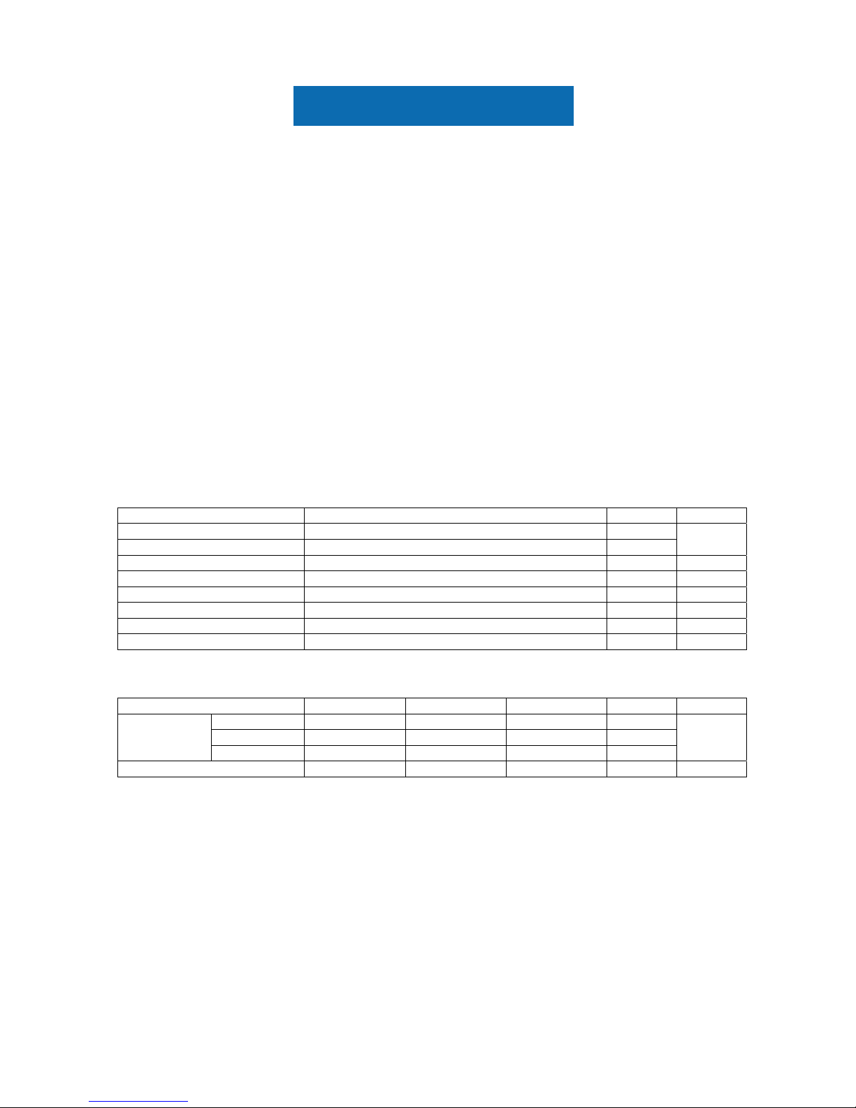
1.4 GENERAL SPECIFICATI0NS
etoN tinU noitacificepS metI
mm )lanogaid ”0.51( )V(1.822 x )H(1.403 aerA evitcA
mm )V(1.232 x )H(2.803 aerA gninepO lezeB
(1)
- - xirtam evitca TFT iS-a tnemelE revirD
- lexip 867 x .B.G.R x 4201 rebmuN lexiP
- mm )W(792.0 x )H(792.0 hctiP lexiP
- - epirts lacitrev BGR tnemegnarrA lexiP
- roloc 772,491,61 sroloC yalpsiD
- - etihw yllamroN edoM evissimsnarT
1.5 MECHANICAL SPECIFICATIONS
Item Min. Typ. Max. Unit Note
Horizontal(H) - 331.6 - mm
Vertical(V) - 254.76 - mm
Module Size
Depth(D) - 13.0 - mm
(1)
Weight - - 1,350 g -
Note (1) Please refer to the attached drawings for more information of front and back outline dimensions.

Panel Specification
2. ABSOLUTE MAXIMUM RATINGS
2.1 ABSOLUTE RATINGS OF ENVIRONMENT
Value
Item Symbol
Min. Max.
Unit Note
Storage Temperature TST -20 +60 ºC (1)
Operating Ambient Temperature TOP 0 +50 ºC (1), (2)
H ytidimuH egarotS
ST
5 85 % -
H ytidimuH noitarepO
OP
20 85 % -
Shock (Non-Operating) S
NOP
- 50 G (3), (5)
Vibration (Non-Operating) V
NOP
- 2 G (4), (5)
Note (1) Temperature and relative humidity range is shown in the figure below.
(a) 85 %RH Max. (Ta ≦ 40 ºC).
(b) Wet-bulb temperature should be 39 ºC Max. (Ta > 40 ºC).
(c) No condensation of water.
Note (2) The temperature of panel surface should be 0 ºC Min. and 60 ºC Max.
Note (3) 6ms, 1 time each ±X,±Y and ±Z directions
Note (4) 10 ~ 500 Hz, 1 cycle/20min. 1.5mm max, 1 hour each X, Y and Z directions
Note (5) At testing Vibration and Shock, the fixtur
e in holding the
module has to be hard and rigid enough
so that the module would not be twisted or bent by the fixture.
Relative Humidity (%RH)
Operating Range
Temperature (ºC)
100
8060 0402- 0 20-40
85
80
40
60
20
5
Storage Range
Panel Specification
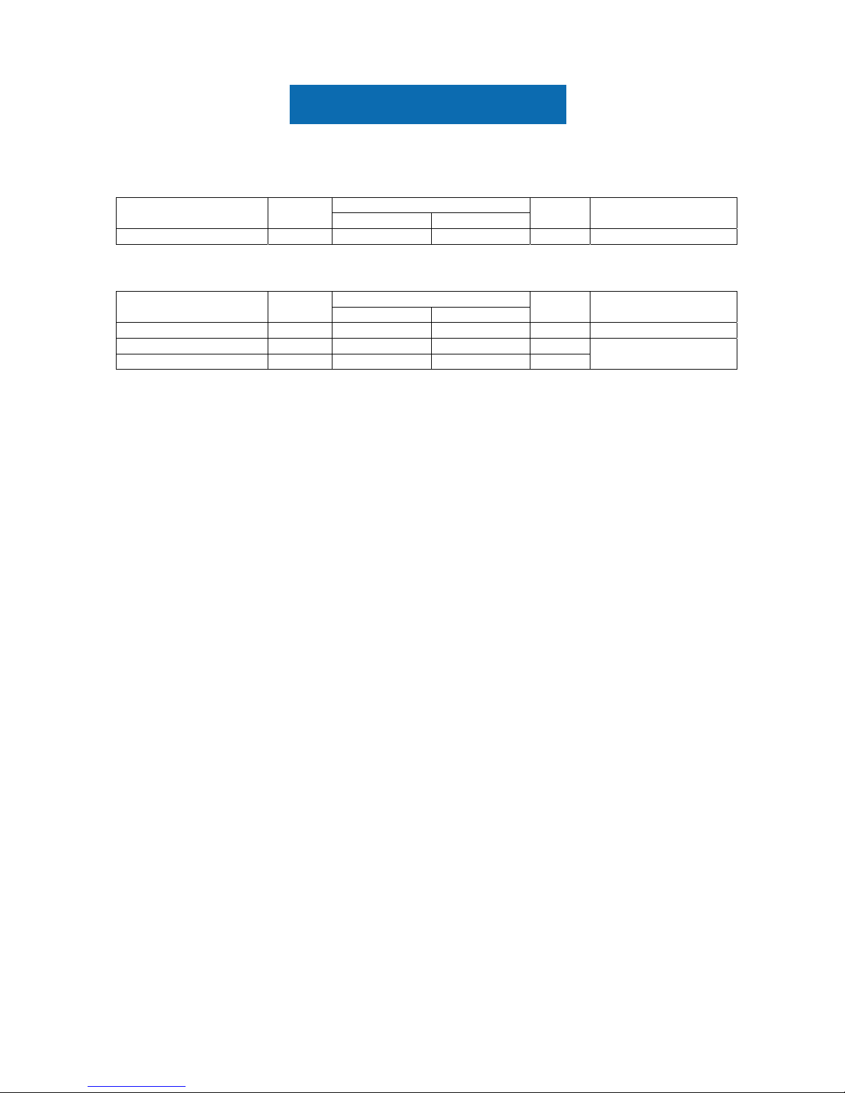
2.2 ELECTRICAL ABSOLUTE RATINGS
2.2.1 TFT LCD MODULE
Value
Item Symbol
Min. Max.
Unit Note
Power Supply Voltage VDD -0.3 4.0 V
2.2.2 BACKLIGHT UNIT
Value
Item Symbol
Min. Max.
Unit Note
Lamp Voltage VL 552 675 V
RMS
(1), (2), IL = 6.0 mA
Lamp Current IL 2.0 6.0 mA
RMS
Lamp Frequency FL 30 80 KHz
(1), (2)
Note (1) Permanent damage to the device may occur if maximum values are exceeded. Function operation
should be restricted to the conditions described under Normal Operating Conditions.
Note (2) Specified values are for lamp (Refer to Section 3.2 for further information).
Panel Specification
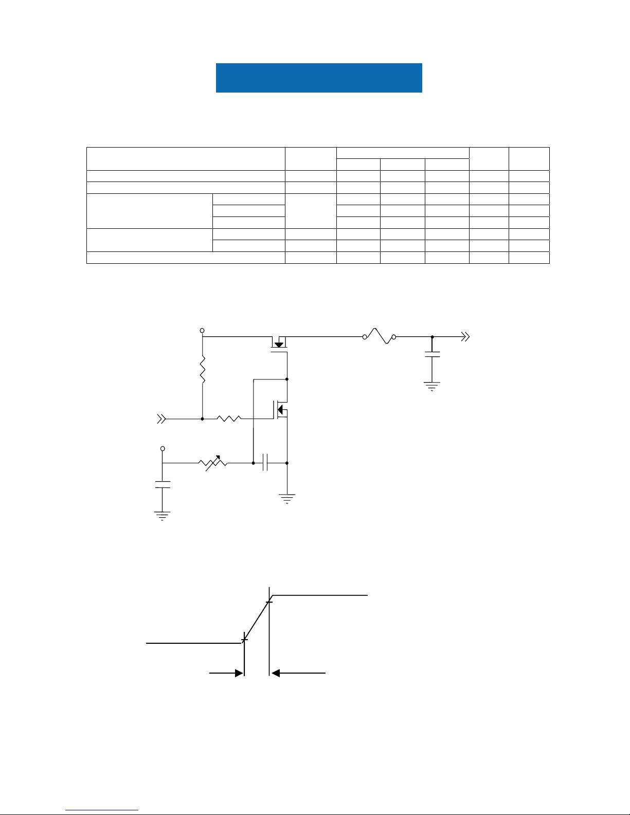
3. ELECTRICAL CHARACTERISTICS
3.1 TFT LCD MODULE
Value
Parameter Symbol
Min. Typ. Max.
Unit Note
V egatloV ylppuS rewoP
DD
3.0 3.3 3.6 V -
I tnerruC hsuR
RUSH
- - 1.5 A (2)
a)3( Am - 053 - etihW
b)3( Am - 035 - kcalB
Power Supply Current
Vertical Stripe
lcc
- 450 - mA (3)c
“H” Level VIH - - 100 mV - Differential Input Voltage for
LVDS Receiver Threshold
“L” Level V
IL
-100 - - mV -
R rotsiseR gnitanimreT
T
- 100 - Ohm -
Note (1) The module should be always operated within above ranges.
Note (2) Measurement Conditions:
470μ s
+3.3V
GND
0.9 V
DD
0.1 VDD
R1
(High to Low)
(Control Signal)
+12V
SW
Q2
C1
1uF
VDD
+3.3V
2SK1470
Q1 2SK1475
47K
R2
1K
VR1
47K
C2
0.01uF
C3
1uF
FUSE
(LCD Module Input)

Panel Specification
Note (3) The specified power supply current is under the conditions at VDD =3.3V, Ta = 25 ± 2 ºC, DC
Current and f
v
= 60 Hz, whereas a power dissipation check pattern below is displayed.
3.2 BACKLIGHT UNIT Ta = 25 ± 2 ºC
Value
Parameter Symbol
Min. Typ. Max.
Unit Note
Lamp Input Voltage VL 552 614 675 V
RMS
IL = 6.0mA
Lamp Current IL 2.0 6.0 7.0 mA
RMS
(1)
- - 870 (25 oC) V
RMS
(2)
Lamp Turn On Voltage VS
- - 1090 (0
o
C) V
RMS
(2)
Operating Frequency FL 30 45 80 KHz (3)
Lamp Life Time LBL 40,000 50,000 - Hrs (5)
Power Consumption PL - 14740 - mW (4), IL = 6.0 mA
Note (1) Lamp current is measured by utilizing a high frequency current meter as shown below:
Note (2) The voltage shown above should be applied to the lamp for more than 1 second after startup.
Otherwise the lamp may not be turned on.
LCD
Module
1
Inverter
A
Current Meter
HV (Pink/ Blue)
LV (White/ Black)
2
Active Area
a. White Pattern
Active Area
b. Black Pattern
Active Area
c. Vertical Stripe Pattern
R
R
R
R
R R
R
R
G
G
G
G
B
B
B
B
B
B
G
G
G
G
B
B
B
B
R
R
 Loading...