

winsonic MCH1045S-XN40C User Manual
User’s Manua
- Model #0&+6;1&
WINSONIC ELECTRONICS Co., LTD
No.290-1, Wen Chung Rd., Taoyuan City, Taiwan, R.O.C
l:+886-3-3704789
ax:+886-3-3704722
E-mail:sales@ewinsonic.com
www.ewinsonic.com
Te
F

AD Board Specification
Panel Specification
Safety Instruction
Product Installation
Contents
General Description
Optical Specifications
Absolute Maximum Ratings
Electrical Specifications
Precautions
Assembly
Trouble Shooting
3
4
5
22
5
6
7
18
21
29
30
Safety Instruction
Read and follow these instructions when connecting and using your LCD monitor:
Operation:
1. Keep the monitor out of direct sunlight and away from stoves or any other heat
source.
2. Remove any object that could fall into ventilation holes or prevent proper cooling
of the monitor's electronics.
3. Do not block the ventilation holes on the cabinet.
4. When positioning the monitor, make sure the power plug and outlet are easily
accessible.
5. If turning off the monitor by detaching the power cable or DC power cord, wait
for seconds before attaching the power cable or DC power cord for normal
operation.
6. Do not subject the LCD monitor to severe vibration or high impact conditions
during operation.
7. Do not knock or drop the monitor during operation or transportation.
Maintenance:
8. To protect your display from possible damage, do not put excessive pressure on
the LCD panel. When moving your monitor, grasp the frame to lift; do not lift the
monitor by placing your hand or fingers on the LCD panel.
9. Unplug the monitor if you are not going to use it for an extensive period of time.
10. Unplug the monitor if you need to clean it with a slightly damp cloth. The screen
may be wiped with a dry cloth when the power is off. However, never use organic
solvent, such as, alcohol, or ammonia-based liquids to clean your monitor.
11. To avoid the risk of shock or permanent damage to the set, do not expose the
monitor to dust, rain, water, or excessive moisture environment.
12. If y
our monitor gets wet, wipe it with dr
y cloth as soon as possible.
13. If foreign substance or water gets in your monitor, please turn the power off
immediately and disconnect the power cord. Then, remove the foreign substance
or water, and send it to the maintenance center.
14. Do not store or use the LCD monitor in locations exposed to heat, direct sunlight
or extreme cold.
15. In order to maintain the best performance of your monitor and use it for a longer
lifetime, please use the monitor in a location that falls within the following
temperature and humidity ranges. Temperature: 5-35°C 41-95°F

Product Installation
1. Switch off the power on both your monitor and your computer. The Power Switch
is located in the right of the monitor.
2. Connect the power cord to the AC outlet, and connect the power to the monitor
through the AC/DC adapter.
3. VGA Signal-Plug one end of the 15-pin signal cable to the video signal connector
at the rear of the PC system and the other end to the monitor. Secure the
connectors with the screws on the cable connector at both ends.
4. (Optional) DVI Signal-Plug one end of the DVI signal cable to the video signal
connector at the rear of the PC system and the other end to the monitor. Secure
the connectors with the screws on the cable connector at both ends.
5. (Optional) HDMI Signal-Plug one end of the HDMI signal cable to the video
signal connector at the rear of the PC system and the other end to the monitor.
Secure the connectors with the screws on the cable connector at both ends.
6. (Optional) RS232 Connection- Plug one end of RS232 cable to com-port
connector on your PC system and the other end to the monitor. Secure the
connectors with the screws on the cable connector at both ends.
Panel Specification
1. GENERAL DESCRIPTION
1.1 OVERVIEW
0&+6;1& is a 10.4” TFT Liquid Crystal Display module with 2-CCFL backlight unit and 30-pin-and-1ch
LVDS interface. This product supports 1024 x 768 XGA format and can display true 16.2M colors (6-bits
colors with FRC). The inverter module for backlight is not built-in
.
1.2 FEATURES
- Excellent brightness (400 nits)
- Ultra high contrast ratio (1200:1)
- Fast response time (Ton+Toff average 25 ms)
- High color saturation NTSC 57%
- XGA (1024 x 768 pixels) resolution
- DE (Data Enable) only mode
- LVDS (Low VoltageDifferential Signaling) interface
- Ultra wide viewing angle: 176(H)/ 176(V) (CR>10) Super MVA technology
-180 degree rotation display option
-Color reproduction (Nature color)
1.3 APPLICATION
- TFT LCD for Avionics and Industrial applications
- High brightness, multi-applications display
1.4 GENERAL SPECIFICATI0NS
Item Specification Unit Note
Active Area 210.4 (H) x 157.8 (V) (10.4” diagonal) mm
Bezel OpeningArea 215.4 (H) x 161.8 (V) mm
(1)
Driver Element a-si TFT active matrix - Pixel Number 1024 x R.G.B. x 768 pixel Pixel Pitch(Sub Pixel) 0.0685 (H) x 0.2055 (V) mm Pixel Arrangement RGB vertical stripe - Display Colors 16.2 M color Display Operation Mode Transmissive mode / Normally black - -
Surface Treatment
Anti-Glare coating (Haze 25%)
Hard coating (3H)
- -
1.5 MECHANICAL SPECIFICATIONS
Item Min. Typ. Max. Unit Note
Horizontal(H) 225 225.5 226 mm
Vertical(V) 175.8 176.3 176.8 mm
(1)
Module Size
Depth(D) - 10.17 10.67 mm -
Weight 430 480 530 g -
Note (1) Please refer to the attached drawings for more information of front and back outline dimensions.
Panel Specification
2. ABSOLUTE MAXIMUM RATINGS
2.1 ABSOLUTE RATINGS OF ENVIRONMENT
Value
Item Symbol
Min. Max.
Unit Note
Storage Temperature T
ST
(-20) (+70) ºC (1)
Operating AmbientTemperature T
OP
(-10) (+60) ºC (1), (2)
Shock (Non-Operating) S
NOP
- (220) G (3),(5)
Vibration (Non-Operating) V
NOP
- (1.5) G (4), (5)
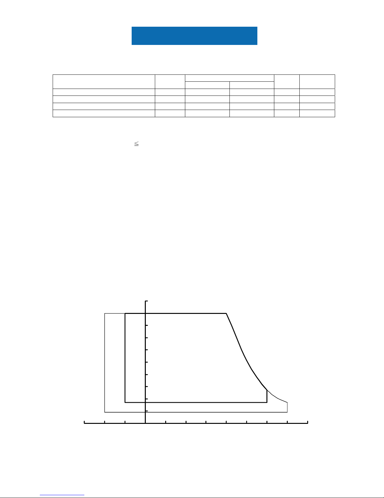
Note (1) Temperature and relative humidity range is shown in the figure below.
(a) 90 %RH Max. (Ta
40 ºC).
(b) Wet-bulb temperature should be 39 ºC Max. (Ta > 40 ºC).
(c) No condensation.
Note (2) The maximum operating temperature is based on the test condition that the surface temperature of
display area is less than or equal to 80 ºC with LCD module alone in a temperature controlled chamber.
Thermal management should be considered in your product design to prevent the surface temperature
of display area from being over 80 ºC. The range of operating temperature may degrade in case of
improper thermal management in your product design.
Note (3) 2 ms, half sine wave, 1 time for ± X, ± Y, ± Z.
Note (4) 10 ~ 300 Hz, 10 min, 1 time each X, Y, Z.
Note (5)At testing Vibration and Shock, the fixture in holding the module has to be hard and rigid enough so that
the module would not be twisted or bent by the fixture.
0
10
20
30
40
50
60
70
80
90
100
-30 -20 -10 0 10 20 30 40 50 60 70 80
Temperature (ºC)
Relative Humidity (%RH)
Storage Range
Operation Range
Panel Specification
2.2 ELECTRICAL ABSOLUTE RATINGS
2.2.1 TFT LCD MODULE
Value
Item Symbol
Min. Max.
Unit Note
Power Supply Voltage Vcc -0.3 4.0 V
Input Signal Voltage VIN -0.3 3.6 V
(1)
3. ELECTRICAL CHARACTERISTICS
3.1 TFT LCD MODULE Ta= 25 ± 2 ºC
Value
Parameter Symbol
Min. Typ. Max.
Unit Note
Power Supply Voltage V
CC
3.0 3.3 3.6 V (1)
Power Supply Ripple Voltage V
RP
- - 100 mV
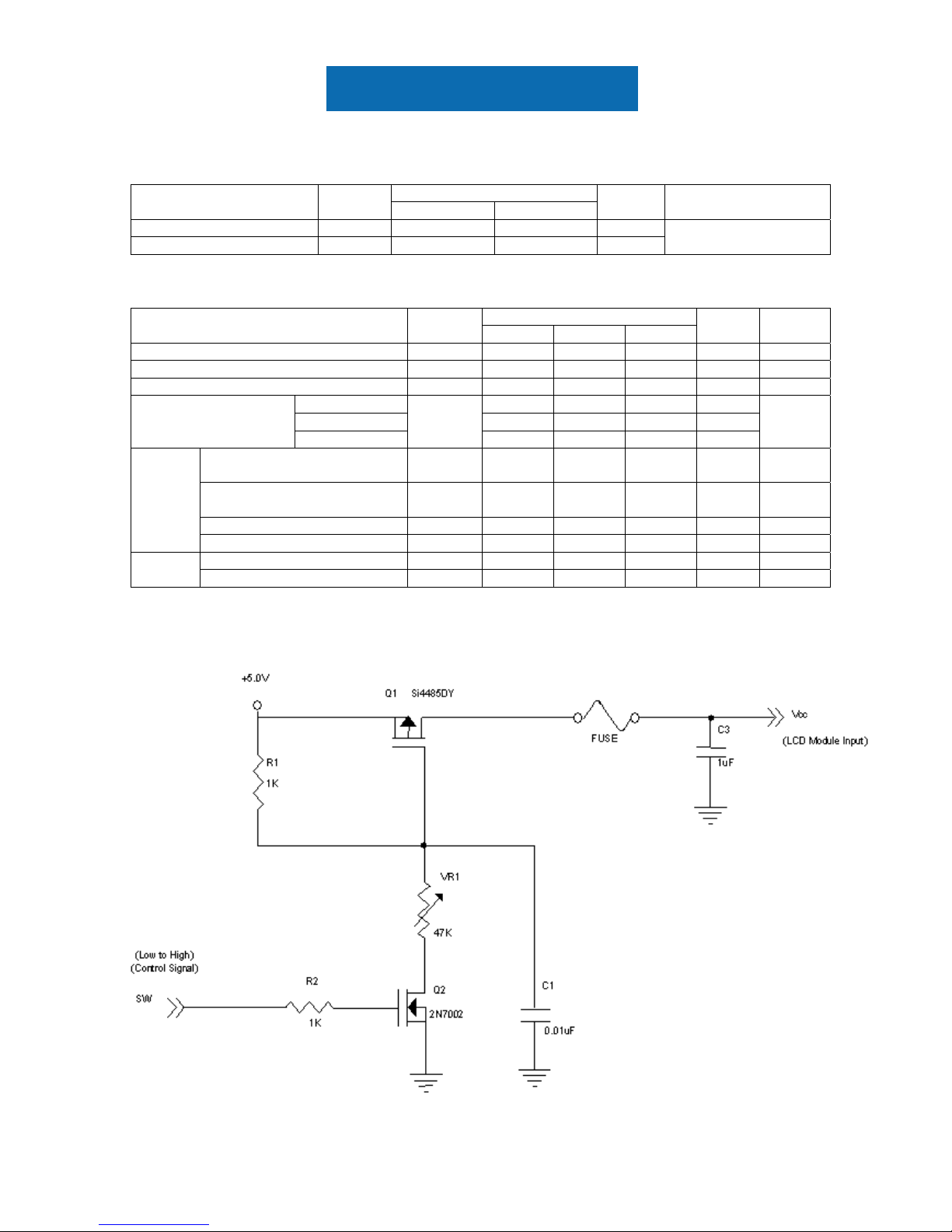
Rush Current I
RUSH
- - 1.8 A (2)
White - 1.1 1.4 A
Black - 0.8 - A
Power Supply Current
Vertical Stripe
I
CC
- 1.0 - A
(3)
Differential Input High
Threshold Voltage
V
LVTH
- - +100 mV
Differential Input Low
Threshold Voltage
V
LVTL
-100 - - mV
Common Input Voltage V
LVC
1.125 1.25 1.375 V
LVDS
Interface
Terminating Resistor R
T
100 ohm
Input High Threshold Voltage V
IH
2.7 - 3.3 VCMOS
interface
Input Low Threshold Voltage V
IL
0 - 0.7 V
Note (1) The assembly should be always operated within above ranges.
Note (2) Measurement Conditions:
Panel Specification
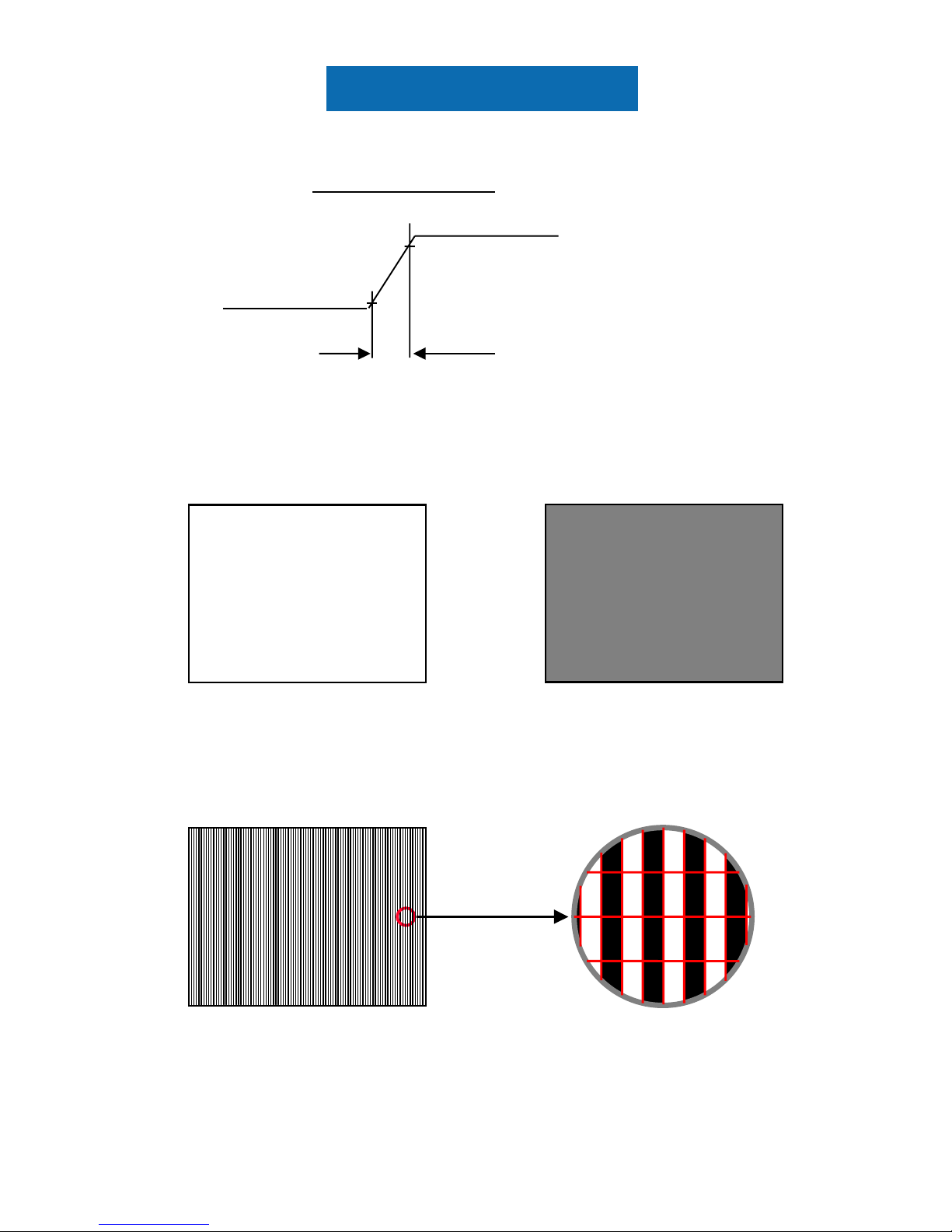
Note (3) The specified power supply current is under the conditions at Vcc = 3.3 V, Ta = 25 ± 2 ºC, f
v
= 60
Hz, whereas a power dissipation check pattern below is displayed.
Active Area
c. Vertical Stripe Pattern
R
R
R
R
R R
R
R
G
G
G
G
B
B
B
B
B
B
G
G
G
G
B
B
B
B
R
R
Active Area
Active Area
a. White Pattern
b. Black Pattern
Vcc rising time is 470us
470µs
+3.3V
GND
0.9Vcc
0.1Vcc
Panel Specification
3.2 BACKLIGHT UNIT
3.2.1 CCFL (Cold Cathode Fluorescent Lamp) CHARACTERISTICS (
Ta = 25 ± 2 ºC)
Value
Parameter Symbol
Min. Typ. Max.
Unit Note
Lamp Voltage V
W
460
V
RMS
IL = 7.0mA
Lamp Current I
L
6.5 7 7.5
mA
RMS
(1)
770(25 )
V
RMS
(2)
Lamp Starting Voltage V
S
960(0 )
V
RMS
(2),
Operating Frequency F
O
45 80 KHz (3)
Lamp Life Time L
BL
50,000
Hrs (4)
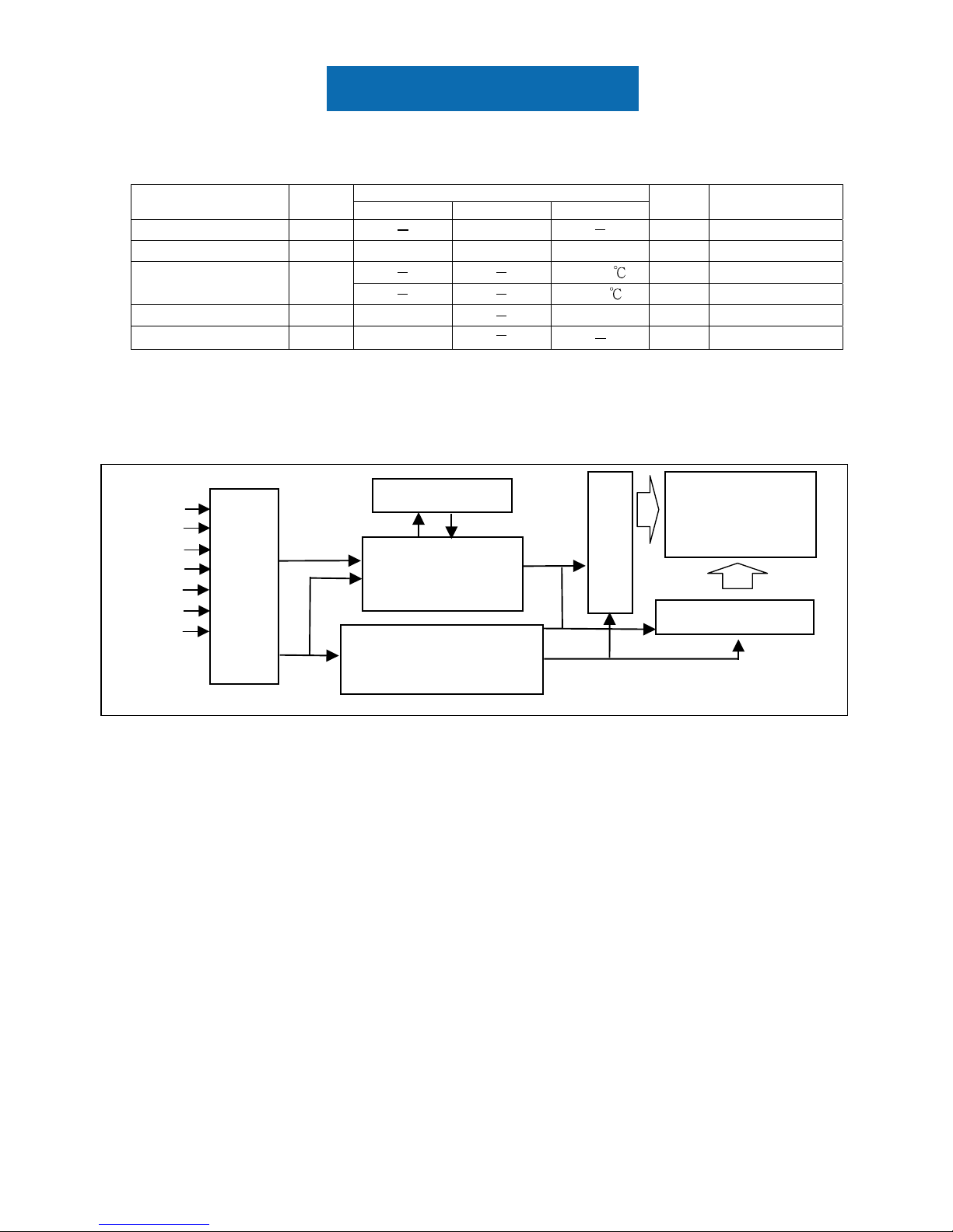
4. BLOCK DIAGRAM
4.1 TFT LCD MODULE
TFT LCD PANEL
(1024x3x768)
DATA DRIVER IC
SCAN DRIVER IC
DC/DC CONVERTER &
REFERENCE VOLTAGE
INPUT CONNECTOR
(JAE,FI-XB30SRL-HF11)
GND
Vcc
FRAME BUFFER
RX0(+/-)
RX1(+/-)
RX2(+/-)
RX3(+/-)
RXCLK
(
+/-
)
TIMING
CONTROLLER
 Loading...