

Winradio WR-G35DDCi Application Manual

WR-G35DDCi Multichannel Coherent Application Guide
WiNRADiO®
WR-G35DDCi
Multichannel Coherent Application Guide
1

WR-G35DDCi Multichannel Coherent Application Guide
Table of contents
1 Introduction ........................................................................................................................ 3
2 Parts description of the coherent system ....................................................................................... 4
2.1 WR-G35DDCi connectors ......................................................................................................... 4
2.2 The WiNRADiO Coherence Clock & 1PPS Kit (WR-CC1PPS-100) ............................................. 5
2.2.1 Coherent clock generator board with 1PPS input ........................................................... 6
2.2.2 PCIe connector ................................................................................................................ 7
2.2.3 SMA connectors for sampling clock output .................................................................... 7
2.2.4 Digital synchronization interface ..................................................................................... 7
2.2.5 Frequency reference output REF OUT ............................................................................. 8
2.2.6 Frequency reference input REF IN ................................................................................... 8
2.2.7 1PPS trigger input ............................................................................................................ 8
2.2.8 Locked indicator .............................................................................................................. 8
2.2.9 SMA patch cables for coherent clock distribution .......................................................... 9
2.2.10 Digital synchronization cables for each WR-G35DDCi receiver ...................................... 9
2.2.11 Digital synchronization cable for the Coherent clock generator board ........................ 10
2.2.12 Frequency reference SMA interconnect cable .............................................................. 10
2.2.13 SMA terminators ........................................................................................................... 11
2.2.14 Sampling clock oscillator input and outputs ................................................................. 12
2.2.15 SMA jumper cable ......................................................................................................... 12
2.2.16 Pin header for disabling the sampling clock oscillator .................................................. 13
3 Standard installation of up to eight receivers ............................................................................... 14
3.1 Preparing the receivers for installation into a PC.................................................................. 14
3.2 Installing the receivers into the PC ........................................................................................ 16
3.3 Installing the digital synchronization cable onto the coherent clock generator ................... 16
3.4 Connecting the coherent ADC sampling clock ...................................................................... 17
3.5 Installing the coherent clock generator board into the PC ................................................... 18
3.6 Connecting the digital synchronization interconnection ...................................................... 18
3.7 Choosing the frequency reference ........................................................................................ 19
3.8 Power up and driver installation ........................................................................................... 19
4 Extended installation of up to sixteen receivers ........................................................................... 20
4.1 Connecting two Coherent clock generator boards ............................................................... 20
4.2 Installation of receivers ......................................................................................................... 22
5 Technical specification .................................................................................................................. 24
Contacts ................................................................................................................................................. 25
2
WR-G35DDCi Multichannel Coherent Application Guide
1 Introduction
The WiNRADiO WR-G35DDCi receiver optionally provides multichannel coherent operation. A
minimum of two and up to sixteen receivers can be coupled together for multichannel
operation.
To couple up to eight receivers, the WR-CC1PPS-100 ‘WiNRADiO WR-G35DDCi Coherence
Clock & 1PPS Kit’ has to be used, which is described in section 2.2. To couple from nine to
sixteen receivers, two Kits have to be used. For more than sixteen channels please contact
WiNRADiO.
For coherent operation, all WR-G35DDCi receivers must be clocked at exactly the same
frequency and phase. To achieve this requirement, it is necessary to distribute a sampling
clock from a single low phase noise clock source. Therefore the receivers have to be
equipped with an ADC Clock Input Option (/CR) for external sampling clock provision.
Similar to the sampling clock, all commands and operations of the receivers must be
synchronized accordingly to the coherent sampling clock. For this reason the receivers have
an external interconnection for digital synchronization, which is also provided on receivers
with an ADC Clock Input Option (/CR)
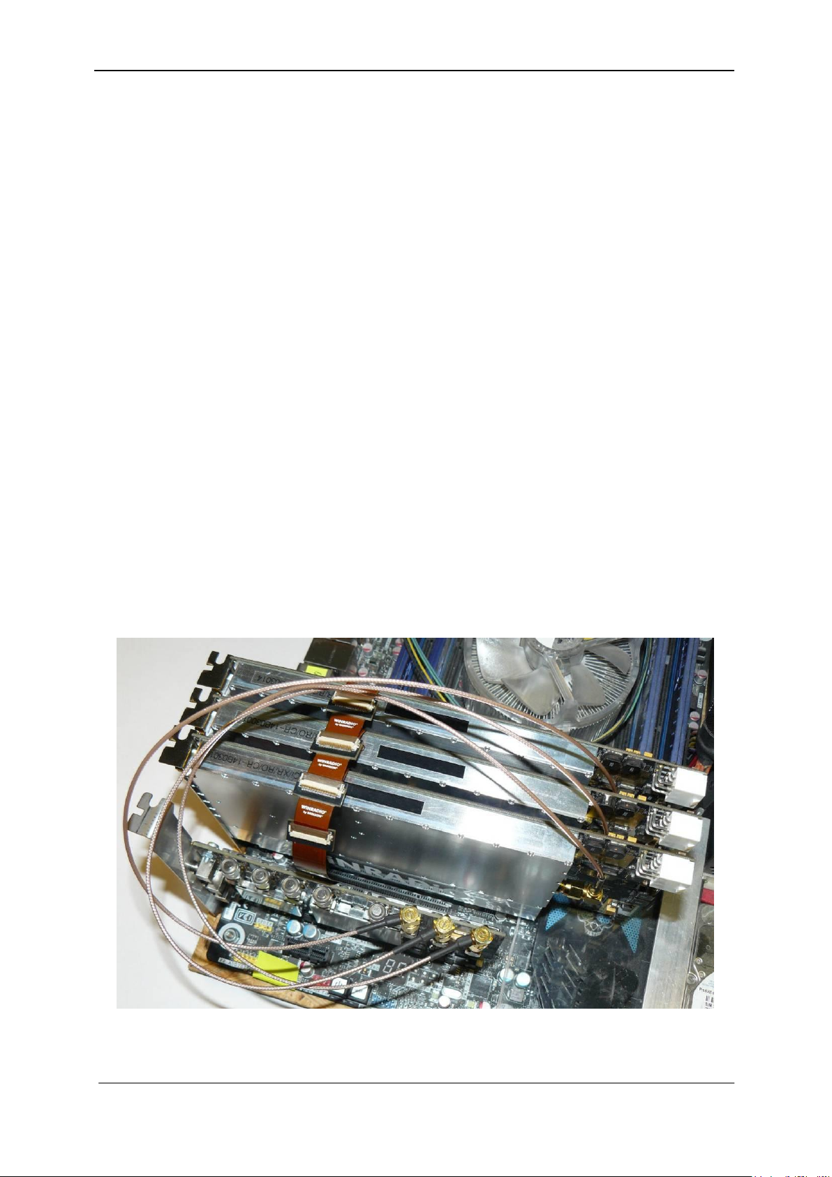
An example of a coherent three channel system is shown in Picture 1-2.
Picture 0-2: An example of three WR-G35DDCi receivers in coherent configuration, installed
into a PC
3
WR-G35DDCi Multichannel Coherent Application Guide
2 Parts description of the coherent system
2.1 WR-G35DDCi connectors
The connectors required for coherent operation of the WR-G35DDCi receivers are shown in
Pictures 2-1 and 2-2 (present when the /CR option has been fitted):
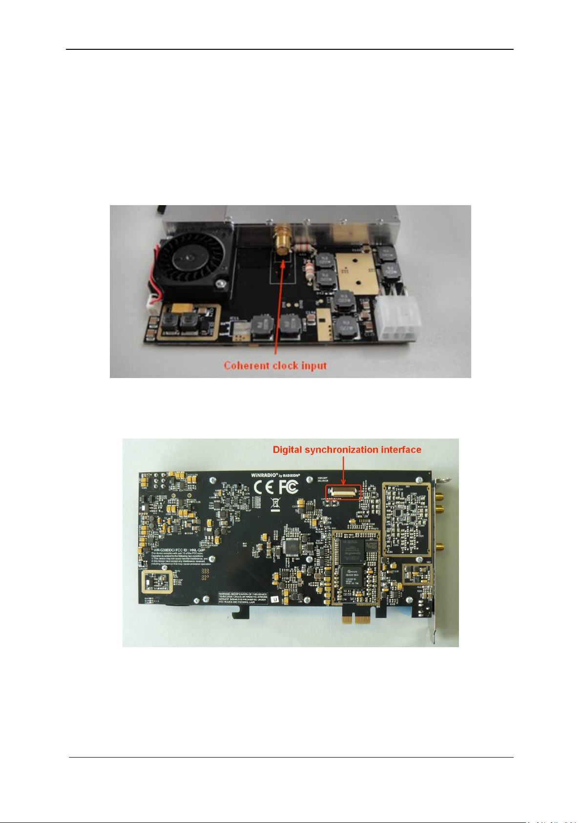
Picture 2-1: Rear panel connectors of the WR-G35DDCi
Picture 2-2: Digital synchronization connector of the WR-G35DDCi, viewed on the PCB side
4
WR-G35DDCi Multichannel Coherent Application Guide
6
2
5
1
3
4
7
9
8
9x
7x 8x
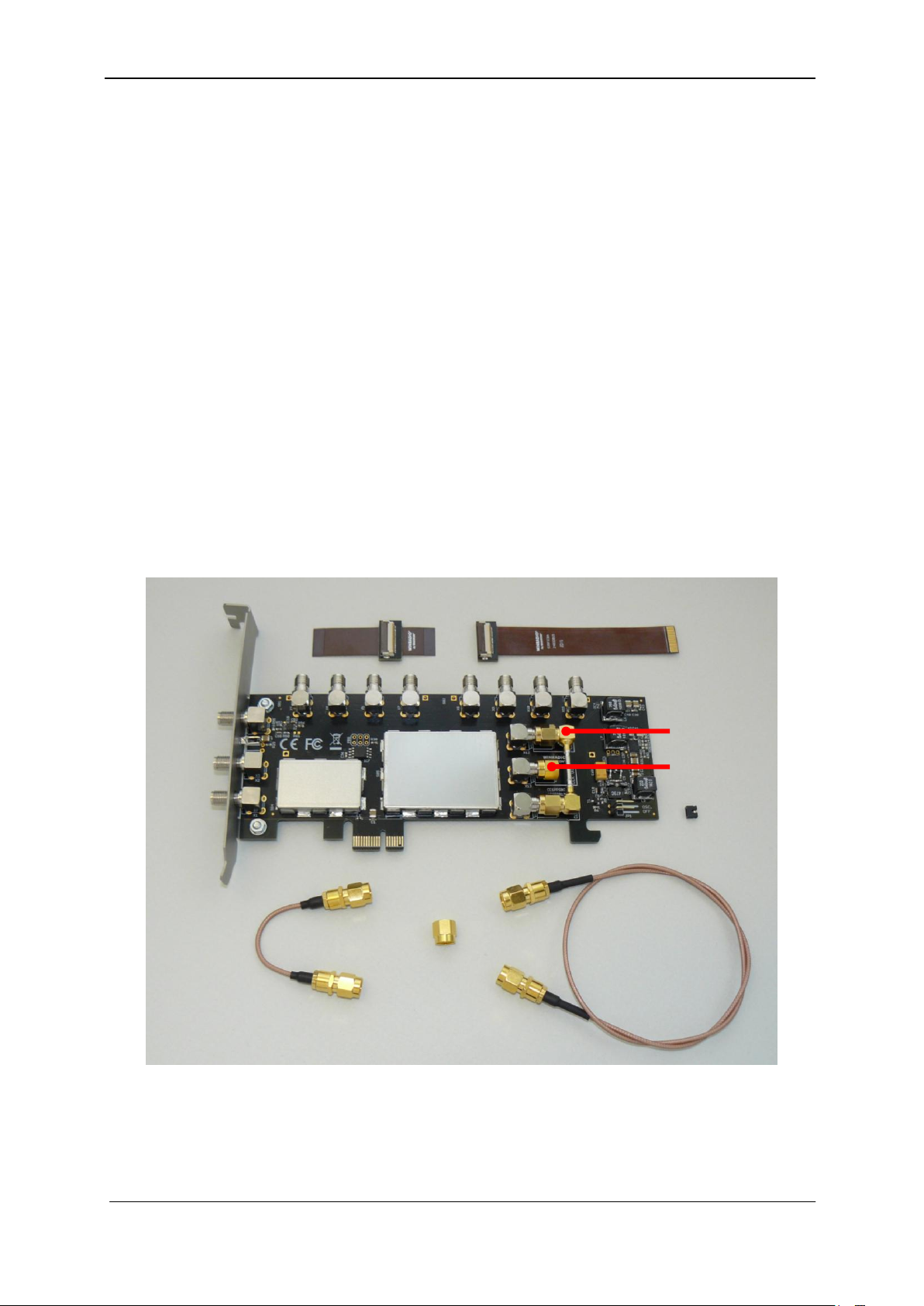
2.2 The WiNRADiO Coherence Clock & 1PPS Kit (WR-CC1PPS-100)
The ‘WiNRADiO Coherence Clock & 1PPS Kit’ (hereafter referred to as the 'Kit') provides
production and distribution of a coherent 100 MHz clock for up to eight WR-G35DDCi
receivers as well as digital synchronization of the receivers. It also features an internal
frequency reference of 0.5 ppm stability, input for external frequency reference and digital
input for a 1PPS pulse or external trigger pulse. The Kit consists of the following components
(shown in Picture 2-3):
1. Coherent clock generator board with 1PPS input
2. SMA patch cables for coherent clock distribution (9 pcs)
3. Digital synchronization cables for each WR-G35DDCi receiver (8 pcs)
4. Digital synchronization cable for Coherent clock generator board
5. Frequency reference SMA interconnect cable
6. SMA terminators (7 pcs + 1 piece pre-installed on the board, see 8 below)
7. Sampling clock SMA coaxial jumper (factory pre-installed on the board)
8. Sampling clock SMA terminator (factory pre-installed on the board)
9. Standard circuit board jumper
Picture 2-3: The WiNRADiO WR-G35DDCi Coherence Clock & 1PPS Kit
5
WR-G35DDCi Multichannel Coherent Application Guide
1
2 6 5
4 3 7
8
11
10
9
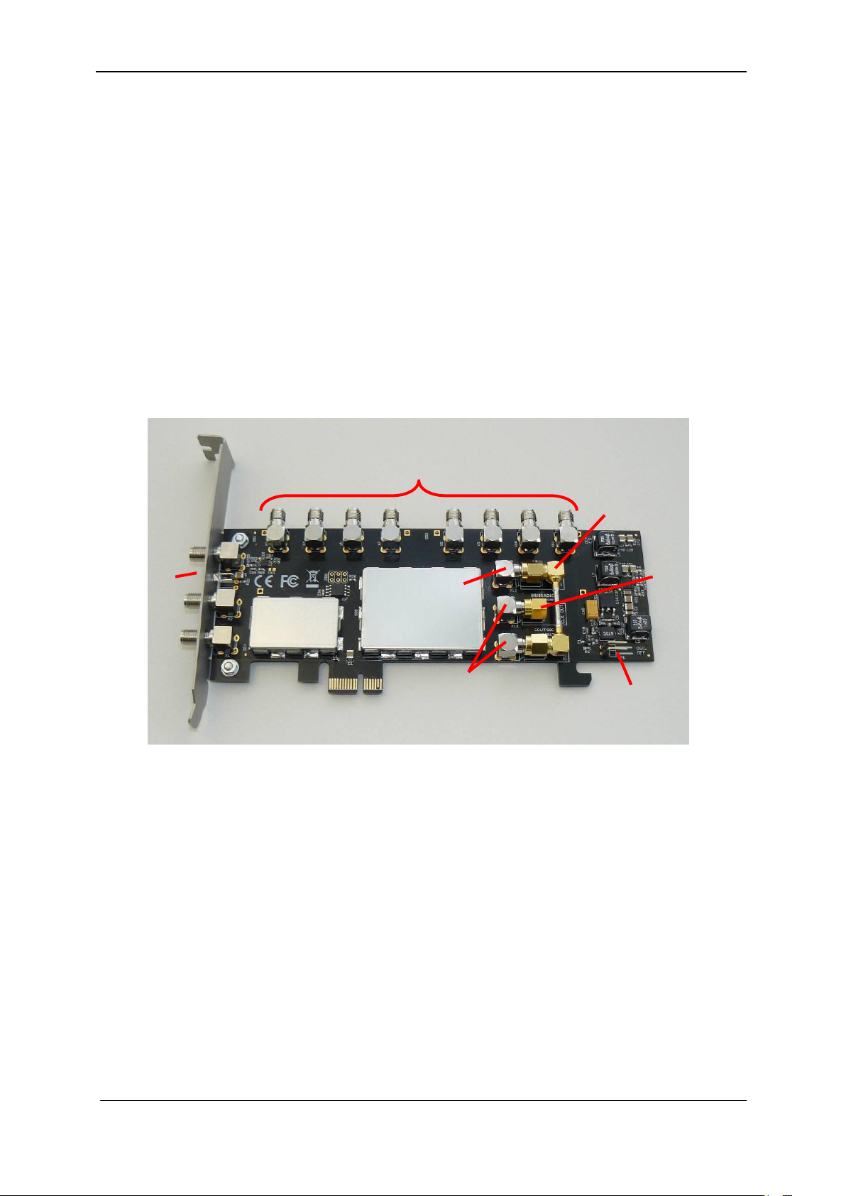
2.2.1 Coherent clock generator board with 1PPS input
The coherent clock generator board is shown in Picture 2-4. It is a PCIe card, which has to
be installed into a PC together with WR-G35DDCi receivers. The board generates a 100 MHz
sampling clock for up to eight WR-G35DDCi receivers. The sampling clock is locked to a
frequency reference, which can be internal or external. It also distributes a 1PPS trigger
signal from the 1PPS input to all connected WR-G35DDCi receivers via the digital
synchronization interface.
No software driver is required for operation of the Coherent clock generator board.
For the technical specification of the board, please refer to chapter 5 of this document.
1 PCIe connector
2 SMA connectors for sampling clock output
3 Frequency reference output REF OUT
4 Frequency reference input REF IN
5 Locked indicator
6 1PPS trigger input
Picture 2-4: Front view of Coherent clock generator board with 1 PPS input
7 SMA connectors for local oscillator output
8 SMA connector for local oscillator input
9 Pin header for disabling the oscillator
10 Factory pre-installed SMA jumper
11 Factory pre-installed SMA terminator
6
WR-G35DDCi Multichannel Coherent Application Guide
2.2.2 PCIe connector
The PCIe connector provides power to the Coherent clock generator board. As there is no
data communication running through the PCIe connector, no software driver is required for
proper operation of the board. However, the board must be installed into a PCIe slot inside a
PC.
2.2.3 SMA connectors for sampling clock output
There are eight SMA connectors for the sampling clock output provided on the Coherent
clock generator board. These are located on the top of the board and are facing upwards.
Each WR-G35DDCi receiver within a coherent group must be connected to one of these ports
using the SMA patch cables (for coherent clock distribution) supplied with the Kit and
described in Section 2.2.9. All ports are equivalent; therefore any receiver within a coherent
group can be connected to any of these ports. However, unused ports have to be terminated
using the 50 OHM SMA terminators for proper operation.
For the technical specification of the sampling clock output signal, please refer to Chapter 5.
2.2.4 Digital synchronization interface
The digital synchronization interface is located on the rear side of the board. It provides a
connection to the digital synchronization interconnection within a coherent group of receivers
via the digital synchronization cable for the Coherent clock generator board (described in
Section 2.2.10). It also distributes the 1PPS signal from the 1PPS input of the Coherent clock
generator board to all WR-G35DDCi receivers within a coherent group. The digital
synchronization cable for the coherent clock generator board attaches to this connector.
The synchronization protocol utilized on this interface is proprietary to WiNRADiO therefore
no further specification is provided.
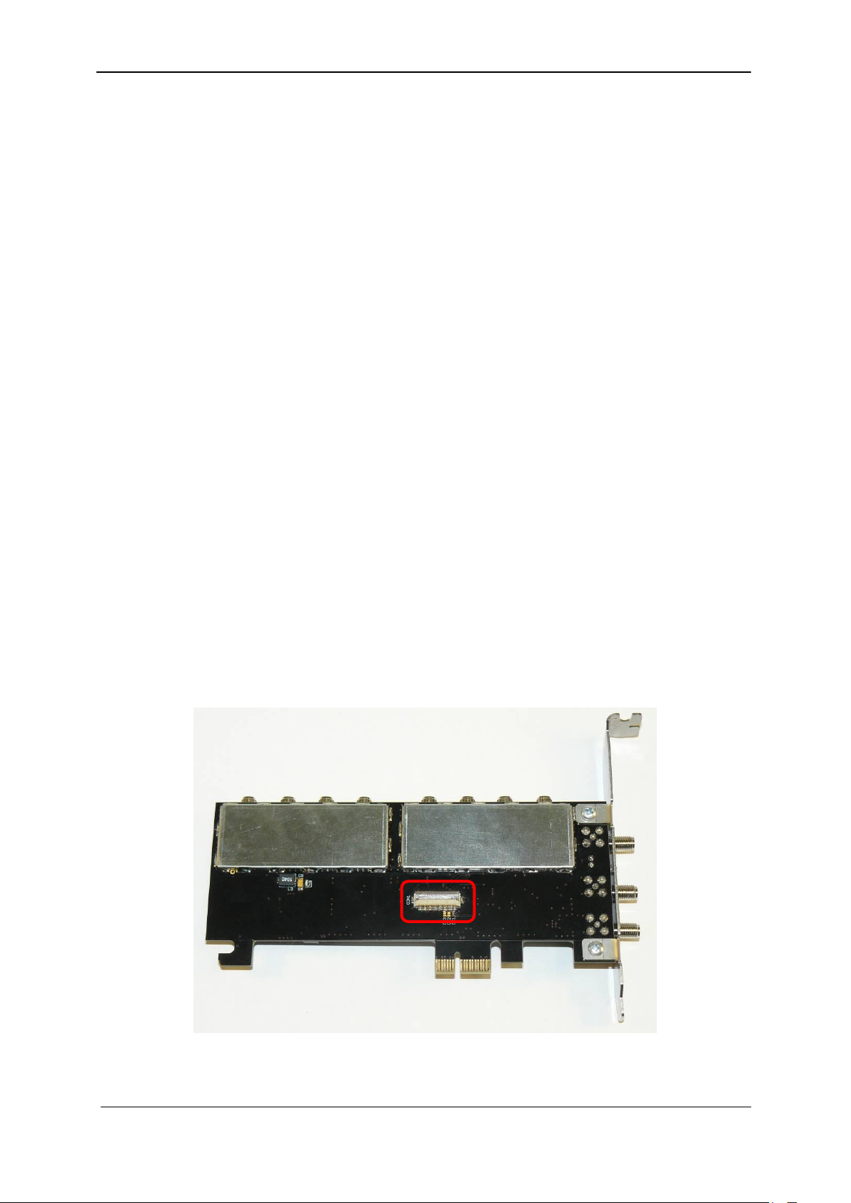
Picture 2-5: Rear view of Coherent clock generator board showing the location of the
digital synchronization interface marked in red
7

WR-G35DDCi Multichannel Coherent Application Guide
2.2.5 Frequency reference output REF OUT
The frequency reference output is an SMA connector providing the 10 MHz (internal)
frequency reference output signal. This output can be connected to the REF IN input port
(Section 2.2.6) if the internal frequency reference operation of the board is required. Use the
Frequency Reference SMA Interconnect cable (described in section 2.2.12 and provided with
the Kit) to connect the REF OUT port to the REF IN port.
If unused, this port must be properly terminated using the 50 OHM terminator.
For the technical specification of the REF OUT, please refer to Chapter 5.
2.2.6 Frequency reference input REF IN
A signal provided to the frequency reference input REF IN serves as a frequency reference
for the 100 MHz sampling clock generator. It is a 50 OHM terminated SMA connector. A 10
MHz reference signal must be provided on this input.
This input can be connected to the REF OUT output port (Section 2.2.5) if the internal
frequency reference operation of the board is required. Use the Frequency Reference SMA
Interconnect cable (described in section 2.2.12 and provided with the Kit) to connect the REF
OUT port to REF IN port.
For the technical specification of the REF IN input, please refer to Chapter 5.
2.2.7 1PPS trigger input
The 1PPS trigger input is provided for applications which require external synchronization
(using 1PPS signal from GPS or similar source) or require external triggering. It is a 50 OHM
terminated SMA connector, which accepts 5V TTL logic levels.
The signal provided to this input is processed by a fast logic comparator and then distributed
to all receivers within a coherent group of receivers over the Digital synchronization
interface.
If unused, this port can be left unconnected.
For the technical specification of the input, please refer to Chapter 5.
2.2.8 Locked indicator
The ‘Locked’ indicator is lit whenever the 100 MHz sampling clock generator is locked to the
frequency reference signal provided at the REF IN port. For more information about the REF
IN port please refer to section 2.2.6.
8
 Loading...