


WiNRADiO
®
WR-G20DWC
High-performance
20 GHz Frequency Down-converter
User’s Guide

WR-G20DWC User’s Guide
2
Published by
WiNRADiO Communications
45-47 Islington Street, Collingwood, Victoria 3066, Australia
Copyright © 2013-2015 WiNRADiO Communications, Melbourne, Australia
All rights reserved.
No part of this book may be reproduced or transmitted in any form or by any means
without written permission of the publisher.
Trademarks
WiNRADiO is a registered trademark of WiNRADiO Communications.
All other brand and product names are trademarks or registered trademarks of their
respective owners.
Printed in Australia

WR-G20DWC User’s Guide
3
Table of contents
Package contents 4
Description 4
Features 5
General 6
WR-G20DWC installation requirements 8
Software installation 8
Running WR-G20DWC software 9
10 MHz reference 10
Contacts 11

WR-G20DWC User’s Guide
4
1. Package contents
The supplied package should contain the following items:
• WR-G20DWC
• SMA-to-SMA 10 MHz reference interconnection cable
• Linear AC/DC power supply
• USB interface cable
• CD ROM with control software
• This user's guide
2. Description
The WiNRADiO WR-G20DWC is a high-performance single-conversion frequency
down-converter suitable for input frequencies up to 20 GHz.
This device contains a high-stability local oscillator, mixer and various filters to convert
an incoming UHF to SHF frequency down to an intermediate frequency of 9 kHz to
2900 MHz, which is then directly applied to the receiver's antenna. This can be used
to extend the frequency range of the WiNRADiO G39DDC and G527e receivers, as
well as third-party products, into the high UHF and SHF regions.
Unlike most simple down-converters, the WR-G20DWC unit ensures excellent
frequency stability by utilizing an ultra-high stability 0.01 ppm OCXO reference
oscillator. This makes it usable even for narrow-band modulation modes, and due to
its low noise figure it can also be used with high-end professional applications.
The WiNRADiO WR-G20DWC down-converter is especially suitable for use with the
WiNRADiO G39DDC-series wideband receivers (WR-G39DDCe and WR-G39DDCi),
whereby it integrates fully transparently to the user, i.e. the frequency entry and display
of these receivers is automatically extended up to 20 GHz.
Physically, the WR-G20WDC unit stacks neatly under or above the WiNRADiO
receivers, thus providing a neat and elegant extension of their capabilities.
Third party receiver products can also be interfaced by using the supplied software
application.

WR-G20DWC User’s Guide
5
3. Features
• Down-conversion input 2900 MHz – 20 GHz
• Bypass input frequency 9 kHz – 2900 MHz
• Output frequency 9 kHz - 2900 MHz
• Ultra-high frequency stability 0.01 ppm
• High dynamic range
• Low noise figure
• Simple installation
• Integrates with WR-G39DDC and WR-G527 receivers
• Suitable for any third-party receivers
• Low power consumption
• USB interface

WR-G20DWC User’s Guide
6
4. General
The WR-G20DWC product has two antenna inputs: RF In: 2900 MHz – 20 GHz,
Bypass In: 9kHz – 2900 MHz.
When the 0 – 2.9 GHz band is selected the signal is switched through to the IF Output.
SWITCH
IF
OUTPUT
BYPASS IN
9 kHz –
2900 MHz
Down converter
10 MHz OCXO
reference
RF In
2.9 –20 GHz
10 MHz
Ref. Out
10MHz
Ref. In
WR-G20DWC block diagram
When a band in the range 2.9 to 20 GHz is selected the signal is down-converted and
switched to the IF output.
An output connector is provided for the 10 MHz OCXO. This signal should be looped
back into the Ref. In connector, or an external 10 MHz high stability reference used.
The WR-G20DWC is controlled by a PC via the USB 2.0 interface (the device is also
USB 1.1 compatible) using WiNRADiO supplied software. When used with G39DDC
receivers, the control software becomes a "plugin" of the standard receiver control
software, which will make the WR-G20DWC usage entirely transparent to the user:
The receiver frequency entry and display becomes automatically extended to 20 GHz
and the down-conversion and internal path switching is controlled automatically.
Third-party receivers can be also used with WR-G20DWC, for which an external
program application is supplied, making it possible to control the down-conversion and
internal path switching manually by the user.
WR-G20DWC User’s Guide
7
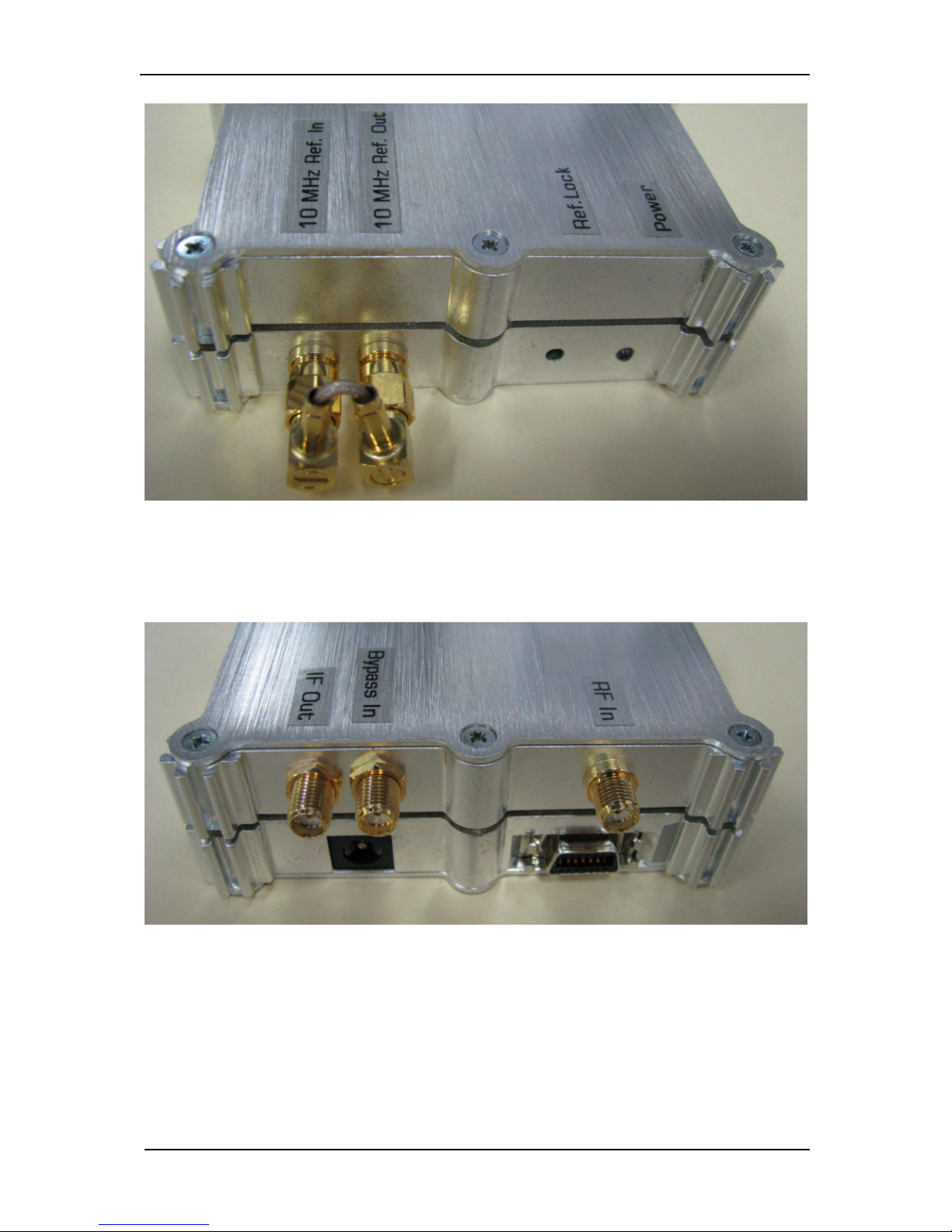
Front panel
Rear panel

WR-G20DWC User’s Guide
8
5. WR-G20DWC installation requirements
●
Operating system: Windows 2000, XP, XP64, Vista, Vista 64, 7, 7/64
(please contact us about Linux support if required)
●
3 MB of hard disk free space
●
WR-G20DWC
6. WR-G20DWC software installation
1. Make sure that WR-G20DWC is not yet connected to the PC.
2. Run the executable file 'G20DWC-install-vvv.exe' (where 'vvv' is the version of
software).
3. Follow the instructions of the installer which will take you through the installation
process.
4. Windows may show some additional dialogs which will ask you to allow driver
installation or some similar dialogs - please answer with positive answers (i.e.
"yes, I want to install the driver").
5. Connect antennas to the corresponding inputs of WR-G20DWC.
6. Connect the WR-G20DWC to your computer using a WiNRADiO USB cable and
insert the power supply cable into the WR-G20DWC.
7. After a while the 'Found new hardware wizard' window will appear. Follow the
instructions of the wizard and select the 'Install the software automatically'
option.
8. When the wizard finishes, the WR-G20DWC software is successfully installed.

WR-G20DWC User’s Guide
9
7. Running the WR-G20DWC software
7.1. Usage with third-party receiver.
If more than one WR-G20DWC is connected, and not in use, a
window will appear asking you to select which one to control.
The WR-G20DWC software control panel appears as below:
The WR-G20DWC down-converter has two signal inputs, one being a “Bypass In” for
frequencies 9 kHz to 2900 MHz, and the other “RF In” is a down-converter input for
frequencies 2900 MHz to 20 GHz.
Signals at the “IF Out” connector are in the range 9 kHz to 2900 MHz.
There are 14 sub-bands each having a band select button on the control panel. The
“0-2.9 GHz” bypass input band is switched through to the IF output with no amplification
or frequency conversion.
The table below which appears in the “About” screen shows the IF output frequency
range for each band.

WR-G20DWC User’s Guide
10
The table shows the local oscillator (LO) frequency used on each of the bands above
2.9 GHz and the IF output frequency range for the single-conversion down-converter.
For the bands where the local oscillator frequency is below the selected band, the
output spectrum is non-inverted. For input frequency Fin:
IF frequency = Fin - LO.
For the bands where the local oscillator is above the band the output spectrum is
inverted and
IF frequency = LO - Fin.
The “Power” LED indicates the presence of the 12v DC supply. Clicking on one of the
band select buttons also depresses the “On/Off” button to apply power to the internal
circuitry.
Clicking the “On/Off” button with no band selected turns on the power and it defaults
to the bypass mode i.e. 0 - 2.9 GHz.

WR-G20DWC User’s Guide
11
8. 10 MHz Reference input and output.
10 MHz Ref. Out.
This is the output from the 0.01ppm 10 MHz OCXO. The typical level is +8 dBm or
3.5Vp-p sinusoidal into an open circuit.
10 MHz Ref. In.
If using an external reference source the level should be between –10 dBm min. and
+10 dBm max. To use the internal OCXO, a coaxial link cable is required between the
Ref In and Ref. Out connectors.
The “Ref Lock” LED illuminates to indicate that the down-converter 100 MHz low
phase noise VCXO reference is frequency locked to the 10 MHz reference.

WR-G20DWC User’s Guide
12
9. Contacts
For more information about our products, please visit our Web site
www.winradio.com periodically.
If you would like to receive regular information and tips about our products, you are
welcome to register on-line using our Web page www.winradio.com/subscribe.
If you have any comments, questions or suggestions, please use our general enquiry
form at www.winradio.com/enquiry.
 Loading...