

Winpower G1536B Installation And Operation Manual
ENGINE
DIFFICULTIES
"In order to eliminate a needless waste of time to you, our customer, it is best in case
of engine trouble to contact the local dealer or distributor of that particular engine
within your area. He can often diagnose
a
problem and correct the trouble without
any difficulty. He also will have a stock of spare parts in case something has to be
replaced. All of our engines have National and International distributors or dealers.
There should be no trouble with getting our engine serviced within your area.
We
are always glad to assist you in obtaining full satisfaction from any engine assembled to a Generator of our manufacture but we know that by contacting the
local engine distributor or dealer, a more prompt correction of the engine malady
can
be achieved."
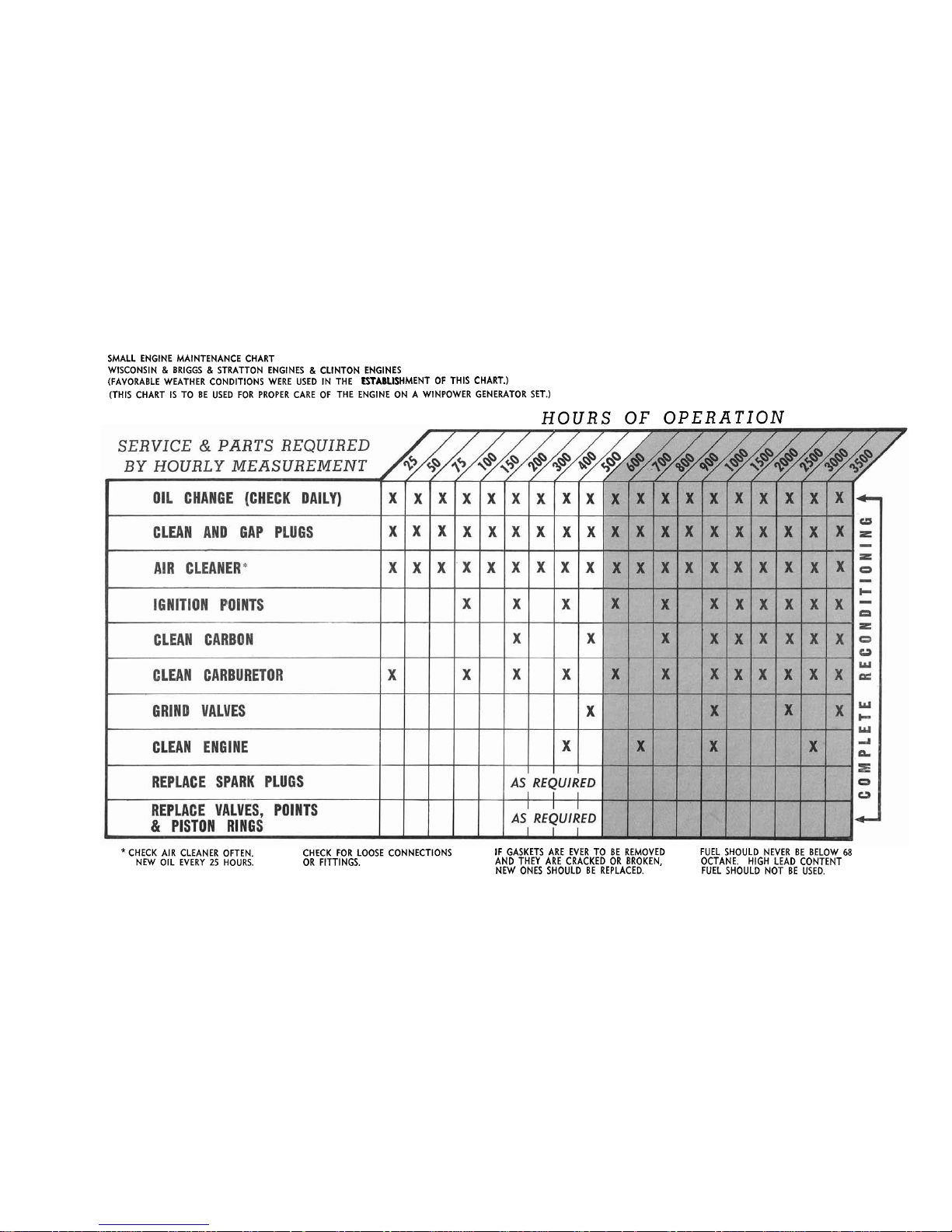
SMALL ENGINE MAINTENANCE CHART
WISCONSIN
&
BRIGGS & STRATTON ENGINES & CLINTON ENGINES
(FAVORABLE WEATHER CONDITIONS WERE USED
IN THE
ESTABLISHMENT OF THIS CHART.)
(THIS CHART
IS
TO BE USED FOR PROPER CARE OF THE ENGINE ON A WINPOWER GENERATOR SET.)
HOURS OF OPERATION
*
CHECK AIR CLEANER OFTEN.
NEW OIL EVERY
25
HOURS.
CHECK FOR LOOSE CONNECTIONS
IF GASKETS ARE EVER TO BE REMOVED FUEL SHOULD NEVER BE BELOW
68
OR FITTINGS. AND THEY ARE CRACKED OR BROKEN, OCTANE. HIGH LEAD CONTENT
NEW ONES SHOULD BE REPLACED. FUEL SHOULD NOT BE USED.
Each Generator
is
carefully inspected at the Factory and run until the brushes are
satisfactorily seated.
Then
it
is
checked for correct output under average operating
conditions.
When unpacking the machine, be sure to inspsct
it
carefully to see that no damage
occurred in transit.
If damage
is
noted, notify the transportation company ime-
diately and have them
write
the nature of the damage on the freight bill, so that
a claim can be filed
if
necessary.
If
upon installation a new Generator does not work properly,
check all of the elec-
trical connections and the Generator speed before assuming that the Generator
is
not
performing satisfactorily,
LOCATION
For best service from a ~ermanently installed unit,
it
should be installed in
a
reasonably clean and dry location.
Excessive moisture has a tendency to deterio-
rate
the electric insulation and damp surfaces always greatly increase the possi-
bility of shorts and grounds,
The surroundings should be relatively free from dirt
and dust because these or other foreign articles have a tendency to clog the venti-
lation slots, and thus cause excessive heating, This dust and dirt
is
also another
cause of rapid brush wear,
During the operation of the Generator Set, considerable heat
is
given off
by
the
engine, this thus
merits
a
good and adequate ventilation system to prevent temperature from becoming excessive. Without proper ventilation both the Engine and Generator can suffer severe damage. Under no circumstances should the temperature in
the room
be
allowed to reach 1200F.
Rxha~ist gases from Gasaline Engines are extremely poisonous!
Whenever an engine
is
installed indoors, exhaust fumes
must
be vented to the outside.
The engine should
be installed about two feet from the outside wall so the exhaust pipe
will
be
kept
short and
yet the engine
will
be a safe distance from the
wall.
Using an exhaust
pipe that
is
too small or too long
will
cause excessive back-pressure which
will
cause the engine to heat up excessively and eventlially cause serious damage to the
engine.
Pine the same
size as the exhaust hole in the engine
is
satisfactory for distances
not exceeding five feet.
For each additional ten feet use pipe
one
size larger.
Keep the number of elbows to a minimum and make sure that the
outward end of the
pipe
is
tilted slightly downward, so rain and snow do not run into the exhaust
pipe and down into the cylinders of the engine.
Where exhaust noises are to be kept to a minimum in urban areas, an underground
tank made from an old oil drum can be used successfully
if
installed above the
ground water level.
A
fifty gallon oil drum, vented above the ground and with
the bottom knocked out or pierced with holes
is
satisfactory for this purpose.
If
the exhaust pipe slants downward towards
the engine,
a
condensation trap should
be installed near the cylinder head to prevent the
water
which condenses from the
exhaust from flowing back into the cylinders
after
the engine has stopped.
This
condensation trap consists of
a
T
connection, a short piece of pipe and
a
pipe
cap.
A
petcock 3hould also
be
provided
at
the end of the cap so the
water
can
be drained
if
necessary.
The exhaust pipe should be supported so the weight
is
not applied to the engine.
In order to keep vibration of the exhaust pipe to a minimum,
a
24
inch piece of
flexible exhaust tubing should
be
installed between the engine and exhaust pipe.
Generators, which are installed to operate automatically, should preferably be
located where the temperature does not fall much below freezing.
Engines atart
and perform better
if
not subjected to excessively cold temperatures.
Batteries,
if
not fully charged
"my
also be damaged
by
low temperatures.
BASE
-
For best results from a permanently installed Generating Plant, a concrete base
should be used.
Although being mounted on concrete the Generator Set should
be
rubber shock mounted to absorb some of the vibration from the set
as
it
is
run-
ning.
Many owners, who have
small
Generator Sets use a rubber pad instead of
individual shock mounts.
This
is
a
very good application but for every day use
your rubber shock mounts are much better d-ue to the fact that dirt collects
underneath the Generator around the pad.
BA
TTE
RY
1
or 512 Volt batteries rated
at
72
ampere-hours or more
is
recommended for
starting Remote Start or
Elect,ric Start Plants of over 1500 Watts capacity.
Two
6-Volt car batteries connected in series
can
do the same job.
This can be done
by connecting the positjive terminal of one batteqr to the negative terminal of
the other. The remaining positive battery
terminal
is
joined to the positive
terminal on the side of the Generator panel and the remaining negative battery
terminal to the negative terminal on the side of the Generator also.
Speaking
of the Generator as we have above, we are referring directly to the-
ene era tor
panel.
All
connections must be clean and tight.
Check the electrolyte (fluid)
in the battery periodially to
be
sure
it
is
above the plates.
Never allow the
battery
to
remain in a discharged condition.
The charge rate on battery charging for the Generator remains constant. There
is
no worry to switch from high to low as on several other
type
Generators.
To
check the battery charger
to
find out
if
it
is
functioning,
start
the unit and
after
it
is
running smoothky, comsct, an ammeter in series to one of the battery
leads.
It
should read between 3 and 5 amps.
CAUTION:
Do not hook ammeter to
battery while cranking engine.
If
this
is
done most generally you
will
burn out
the ammeter. This
is
caused
by
the surge load in cranking.
ENGINE
FUELS
The Remote-Start Generators are equipped with fuel pumps and are designed for
use with small portable tanks or underground tanks.
Manual and Electric Start
Plants are equipped with engine mounted tanks.
The installation included in this manual shows a typical installation
of
an
Auto-
matic Stand-by Generator.
Many states and cities codes require an underground
tank
i.f
gasoline
is
to be used as fuel. In Stand-by service, the Generator may
remain idle for
a
considerable period of time.
If the gasoline has evaporated
fromthe carburetor,
it
becomes necessary to crank the engine until fuel has been
pumped up from the storage tank.
In
some locations a one quart reserve tank or
day tank may be located close to the plant to feed gasoline to the carburetor
by gravity so that
much of the prolonged cranking
is
eliminated.
GASEOUS
FDEL
Gaseous fuels can be used as a fuel for ensnes equipped with special gas-gasoline
carbu-
retion
kits
which are installed at the Factory.
These gaseous fuels may
be
natural or
manufactured gas, or a mixture
of the two, supplied to the customer through regular
gas
mains or liquified petroluem gas
(LP
or LPG) such as butane or propane - these
are
also
referred to as bottle gas since they are delivered in steel tanks under considerable
pressure.
Gaseous fuels are often preferred for permanent installations because of
convenience, safety, cost and cleaner operation.
Engines adapted for burning gaseous fuels are equipped with Model F Ensign Gas Fuel Regulators,
This regulator
is
designed to regulate the proper flow of gas over the entire
load range, from no load to full load on the Generator, and to stop the flow of gas when
the engine
is
stopped,
This
regulator
is
often referred to as the Secondary regulator
because the pressure of the gas from a storage tank or from the high pressure
gas
mains
has already been reduced by a primary regulator.
Gas reaching the secondary regulator
is
usually
at a pressure of four to
six
ounces
per
square inch, (seven to ten inches of water), When the engine
is
not running, that
is
when the pressure at the inlet to the regulator
is
highest, the pressure should not
ex-
ceed six ounces, (with greater pressure the regulator may be unable to stop the flow of
gas
)
,
When the enane Generator
is
running at
full load,
that
is
when the pressure
is
lowest,
it
should not fall below four ounces
-
less pressure may cause the engine to
be
starved for fuel. The engine
will
then lack power and be damaged internally.
Bottled gas, such as propane
is
usually stored in a liquid state in steel
tanks
under
a
pressure in excess of
70
pounds per square inch, Normally, from one-tenth to fifteen-
hundreths gallons of propane fuel
is
required per hour of operation for each horsepower
rating of the engine,
A
primary regulator must be used to reduce the pressure to about
six ounces per square inch,
Natural gas, manufactured gas or a mixture of the two
is
usually delivered at a pressure not exceeding six ounces per square inch, so that no
primary regulator
is
required.
When burning
LP
gas or natural gas having a BTU
content of
1100
or over, the Engine
Generator Plant
will
deliver
its
full rated output,
When burning mixed
gas
(natural
and manufactured) with the rating of
825
BTU,
it
will
deliver up to
80%
of
its
rated
capacity.
When burning manufactured gas of approximately
550
BTU,
it
will
produce up
to of
its
rated capacity.
Natural gas, manufactured gas and bottle gas do not usually ignite
as
readily as gaso-
line. However, since the Generators on remote starting Electric Start Generators crank
the engines at
a
high
rate of speed, no difficulty in starting
is
usually experienced
at normal temperatures.
The use of
LP
bottle gas, however
is
not recommended in freezing
temperatures,
OPERATING
ENGINES
ON
GAS
FUEL
Engines equipped with combination gas-gasoline carburetors
are properly adjusted before
they leave the Factory,
A
tag attached to the
unit
specifies whether the adjustments
were made for gasoline, propane gas
(LPG)
or natural gas.
On
this
tag also will be the
correct pressures for proper operation of
this
unit
with the new type gaseous fuels.
To operate on gasoline:
If the engine
is
equipped with a gasoline tank
it
can be used
in the regular manner,
If the engine does not have a gasolilre
tank
but
is
equipped with
 Loading...