

Winpower DR20, DR600 Installation And Operation Manual
DR20 - DR600
With DGC-2020
Engine Control
DIESEL
GENERATOR
SYSTEMS
INSTALLATION AND
OPERATIONS MANUAL
DR45I4 Shown for Comparison

SAVE THESE INSTRUCTIONS
This manual contains important instructions that
should be followed during installation and maintenance
of the generator and batteries.
Read and understand all instructions in the manual
before starting and operating the generator set.
USING THIS MANUAL
Congratulations on your choice of a Winpower generator set. You have selected a high-quality, precision-engineered generator set designed and tested to give you years
of satisfactory standby service.
To get the best performance from your new engine
generator set, it is important that you carefully read and
follow the operating instructions in this manual.
Should you experience a problem please follow the
“Things To Check” near the end of this manual. The
warranty listed in this manual describes what you can
expect from WINPOWER should you need service assistance in the future.
COPY YOUR MODEL AND SERIAL NUMBER HERE
No other WINPOWER generator has the same serial
number as yours. It is important that you record the number and other vital information here. If you should ever need
to contact us on this unit it will help us to respond to your
needs faster.
TABLE OF CONTENTS
INTRODUCTION i
GUIDE TO PRODUCT SAFETY 1
BASIC INFORMATION 2
Description 2
DGC-2020 Engine Control Layout 3
DGC-2020 Display Operations 5
RECEIVING THE GENERATOR 6
Unpacking the unit 6
Lifting the unit 7
ENGINE GENERATOR INSTALLATION 7
Installation 6
Engine Generator Set Mounting 8
Fuel Installation 8
Lubrication 8
Coolant 8
Battery Installation 9
Battery Charger/Block Heater Wiring 9
Mounting The Transfer Switch 10
AC ELECTRICAL CONNECTIONS 10
DC ELECTRICAL CONNECTIONS 12
INITIAL START-UP 13
EXERCISER CLOCK 14
TROUBLESHOOTING INFORMATION 14
APPENDIX DIRECTORY 15
Appendixes 16-29
12 MONTH WARRANTY 30
PROPER USE AND INSTALLATION
MODEL_____________________________________
SERIAL NUMBER____________________________
'M" Spec. __________________________________
PURCHASE DATE____________________________
DEALER____________________________________
You must be sure your new engine generator set is:
* Properly serviced before starting
* Operated in a well ventilated area
* Properly exhausted and gases safely dispersed
* Wired by a qualified electrician
* Operated only for its designed purposes
* Used only by operators who understand its operation
* Properly maintained
Page i

IMPORTANT SAFETY
2. FIRE HAZARD - Deisel fuel presents a hazard of possible
explosion and/or fire.
INSTRUCTIONS
SAVE THESE INSTRUCTION
This manual contains important instructions that
should be followed during installation and maintenance
of the generator and batteries.
Read and understand all instructions in the manual
before starting and operating the generator set.
This engine generator set has been designed and manufactured to allow safe, reliable performance. Poor maintenance,
improper or careless use can result in potential deadly hazards;
from electrical shock, exhaust gas asphyxiation, or fire. Please
read all safety instructions carefully before installation or use.
Keep these instructions handy for future reference. Take special
note and follow all warnings on the unit labels and in the manuals.
ANSI SAFETY DEFINITIONS
************************************************************
DANGER:
DANGER indicates an imminently hazardous situation which, if
not avoided, will result in death or serious injury. This signal word
is to be limited to the most extreme situations.
***********************************************************
************************************************************
WARNING:
WARNING indicates a potentially hazardous situation which, if
not avoided, could result in death or serious injury.
***********************************************************
a. Do not smoke or use open flame near the generator
set.
b. Keep a fire extinguisher nearby and know its proper use.
Fire extinguishers rated ABC by NFPA are appropriate.
3. DEADLY EXHAUST GAS - Exhaust fumes from any diesel
engine contain carbon monoxide, an invisible, odorless
and deadly gas that must be mixed with fresh air.
a. Operate only in well ventilated areas.
b. Never operate indoors.
c. Never operate the unit in such a way as to allow exhaust
gases to seep back into closed rooms (i.e. through
windows, walls or floors).
4. NOISE HAZARD - Excessive noise is not only tiring, but
continual exposure can lead to loss of hearing.
a. Use hearing protection equipment when working
around this equipment for long periods of time.
b. Keep your neighbors in mind when permanently install-
ing this equipment.
5. CLEANLINESS - Keep the generator and surrounding area
clean.
a. Remove all grease, ice, snow or materials that create
slippery conditions around the unit.
b. Remove any rags or other material that could create
potential fire hazards.
c. Carefully wipe up any fuel or oil spills before starting the
unit.
d. Never allow leaves or other flammable material to build
up around the engine exhaust area.
***********************************************************
CAUTION:
CAUTION indicates a potentially hazardous situation which, if not
avoided, may result in minor or moderate injury. It may also be
used to alert against unsafe practices.
************************************************************
NOTE:
CAUTION is also used on the unit labels and in this manual to
indicate a situation that could result in serious damage or
destruction of the equipment and possible personal injury.
1. ELECTRIC SHOCK - The output voltage present in this
equipment can cause a fatal electric shock. This equipment
must be operated by a responsible person.
a. Do not allow anyone to operate the generator without
proper instruction.
b. Guard against electric shock.
c. Avoid contact with live terminals or receptacles.
d. Use extreme care if operating this unit in rain or snow.
e. Use only three-prong grounded receptacles and
extension cords.
f. Be sure the unit is properly grounded to an external
ground rod driven into the earth.
6. SERVICING EQUIPMENT - All service, including the
installation or replacement of service parts, should be
performed only by a qualified technician.
a. Use only factory approved repair parts.
b. Do not work on this equipment when fatigued.
c. Never remove the protective guards, cover, or recep-
tacle panels while the engine is running.
d. Use extreme caution when working on electrical compo-
nents. High output voltages from this equipment can
cause serious injury or death.
e. Always avoid hot mufflers, exhaust manifolds, and
engine parts. They all can cause severe burns instantly.
f. Installing a generator set is not a “do-it-yourself” project.
Consult a qualified, licensed electrician or contractor.
The installation must comply with all national, state, and
local codes.
g. Always make sure unit is disabled before placing your
hands anywhere near the fan, belts, alternator or water
hoses.
60708-142
Page 1
8122-00
TESTING POLICY:
Before any generator is shipped from the factory, it is fully
checked for performance. The generator is loaded to its full
capacity, and the voltage, current, and frequency are carefully
checked.
Rated output of generators is based on engineering tests of
typical units, and is subject to, and limited by, the temperature,
altitude, fuel, and other conditions specified by the manufacturer
of the applicable engines.
INTRODUCTION AND
DESCRIPTION
** NOTICE **
These units will automatically transfer if a power outage occurs
while running in an exercise mode.
MODEL NUMBER STRUCTURE:
The WINPOWER alpha-numerical numbering system consists of a
base model designation, followed by an options section, separated
by a dash mark. The base component of the model numbering
system identifies an engine type, engine starting method, fuel type,
kilowatt rating, engine manufacturer , and number of generator poles.
Following the separation dash mark is the voltage connection and
optional installed equipment. Options include features like weather
enclosures (housing), base mounted fuel tank sizes, and trailer
options.
PRODUCT DESCRIPTION:
This engine-generator set is designed for unattended remote start
operation. It can be operated as part of a fully automatic standby
power system or independently as a local start unit in a prime power
system. The engine-generator set is fully tested at the factory prior
to shipment to insure proper operation of each individual component
as well as the total system's performance and reliability.
The engine generator set consists of a multi-cylinder, liquid cooled
engine nominally operating at 1800 rpm. The generator frequency
regulation is maintained by the engine governor to within +/- 1.5 hertz
(cps), from no load to rated load for standard mechanical governors
and to within +/- .5 hertz or better for units equipped with an electronic
governor. The generator is a single bearing, direct drive, rotating
field design. The generator is connected to the engine flywheel via
flexible drive disks. The Generator Set is skid mounted with isolation
mounts between the engine and base on all units.
Unit Orientation Note: All references used in this manual for unit
familiarization, access and component locations on the Generator
Set are oriented from a TOP (plan) VIEW with engine at the FRONT
and generator to the REAR.
WINPOWER uses a common junction box for all customer control
and power connections (both AC output and DC control). The
common electrical junction box is always on the left side at the
generator end of the machine.
A customer supplied 12 (or 24) Volt battery is required to complete
the installation. See appendix 1, to identify the voltage, size and CCA
(Cold Cranking Amp) requirements for your specific unit.
The engine is controlled and Generator Set operation is monitored
for safe operation by a programmable microprocessor based Electronic Engine Control Module (ECM) with an LCD digital display. The
Generator Set ECM control is mounted on a vertical pedestal on the
right side of the generator. (Except for the DR10 & DR20 which are
mounted on top the generator housing) The ECM is programmed
with a cycle cranking sequence - 3 cycles of 15 seconds on / 15
seconds off, and a 5 minute cool down delay. The cool down delay
can be changed in the field from 0 to 30 minutes by your dealer. Other
features, timing cycles, set points and signal output capabilities are
possible. Consult factory for procedure and passwords.
Please note that some features or packages, such as NFPA level
I & II, do not have an indication place in this numbering system.
They are issued and built with an M-Spec (i.e. M-10372) number
which can be found on the WINPOWER data tag. When the MSpec is present, supplemental inserts will accompany this
standard manual providing information about the special equipment and features installed. The standard model numbering key
that can be used along with the data tag information and/or Mspec supplements to determine the generator sets ratings and
specifications
MODEL NUMBERING SYSTEM
BUILD YOUR GENSET REQUIREMENT FROM
THE BOTTOM OF THE PAGE TO THE TOP
TRAILER OPTION IF PRESENT UNIT IS MOUNTED ON A
TRAILER WITH FUEL TANK FUEL. TANK SIZES SHOWN BY
PREVOUIS LETTER (SMALL AND MEDUIM FUEL TANKS ONLY)
FUEL TANK SIZE
M = MEDUIM
HOUSING TYPE
H = WEATHER HOUSING (WEATHER-PAK)
S = SOUND ATTENUATED/WEATHER PROTECTIVE (SOUND-PAK)
VOLTAGE
A = SINGLE PHASE 120/240
D = THREE PHASE 120/208
BASE UNIT - OPTIONS SEPARATOR
NUMBER OF POLES ON THE GENERATOR
ENGINE MANUFACTURE
V = VOLVO I = ISUZU (10 & 20 kW)
D = DEUTZ N = NG ENGINES
KILOWATTS
GENERATOR OUTPUT IN KILOWATTS WITH STANDBY
GASEOUS FUEL TYPE
N = NATURAL GAS
P = LIQUID PROPANE VAPOR
STARTING METHOD
FUEL TYPE
G R N 20 I 4 - A H M T
L = LARGES = SMALL
* = NONE
J = THREE PHASE 120/240
L = THREE PHASE 277/480
4 POLES STANDARD
I = IVECO (ALL OTHERS)
L = L/P LIQUID WITHDRAWL
NOT USED WITH DIESEL FUEL
R - REMOTE STARTING
D = DIESEL
G = GASEOUS
SEE CURRENT PRICE SHEET
TO DETERMINE CAPACITY
* = NO HOUSING
G = GM
8122-00
Page 2
60708-142
SPECIFICATIONS
GENERATOR SET:
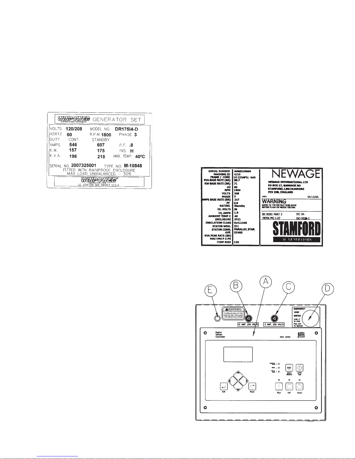
Every WINPOWER Generator Set has its own unique identity data
plate. This data plate identifies the complete unit model number,
the system serial number and has links to the individual components that form the generator set in our factory records. Several of
the major components also have their own individual identity plates
providing additional information to document build data for warranty
and replacement parts.
Typical Winpower Nameplate
Be sure to have the main WINPOWER unit data plate information
recorded inside the front cover of this manual for future reference
and for identification whenever requesting field or factory technical
assistance. Sample data plate is shown for reference. Primary fields
needed for assistance are complete model number, serial number
and especially the M-Spec number. The M-Spec number (if provided) is recorded in the ‘TYPE NO.’ block on the Lower Right of the
plate. See the appendixs in the back of this manual for individual
units specifications and wiring diagram references.
ENGINE:
The rated power of each engine-generator is limited by the
temperature, altitude and all other ambient conditions specified
by the engine manufacturer. Engine power will decrease 3-1/2%
for each 1000 ft. above sea level, and will decrease an additional
1% for each 10 degrees Fahrenheit above 60 degrees Fahrenheit. Units should not be operated in ambient temperature greater
than 125 degrees Fahrenheit.
GENERATOR:
WINPOWER Generators Sets use totally brushless, AVR (AutoVoltage Regulator) controlled broad-range generator ends. The
generator converts rotational mechanical energy into electrical
energy. Standard WINPOWER units are equipped with generators manufactured by Stamford/Newage. Each generator ‘end’
has its own data tag. The unique serial number is stamped on the
data plate and into the upper section of the mounting adapter of
the generator frame. The data label is affixed to the main frame
of the generator on the lower left side, similar to the sample
shown.
ENGINE CONTROL PANEL LAYOUT
Each engine has a nameplate on it that gives the specific engine
model number, build specification and the serial number for the
engine. See the technical data pages in the back of this manual
for individual engine specifications, fuel consumptions and wiring
diagram references.
This manual covers specific operation of the combined engine
generator set. Refer to engine operating and maintenance
instructions for specific instruction on the care and maintenance
of the engine. Oil and fuel requirements along with maintenance
schedules and engine warranty information are provided by the
individual engine manufactures.
** CAUTION **
EQUIPMENT DAMAGE - Be sure to check the engine oil level
frequently as specified in the engine manual.
The engine manufacturer has established an excellent worldwide
engine service organization; engine service is available from a
nearby authorized dealer or distributor; check the Yellow Pages
of the telephone directory under “engines,” or ask the dealer from
whom you purchased the power plant.
60708-142
Page 3
8122-00
A - DGC-2020 Digital Gen-Set Control. See Explanation
below.
B - DC Control Circuit Fuse. The 10 amp DC Circuit Fuse
protects the 12 volt circuits and engine wiring harness against
faults in wiring or control equipment. The fuse also prevents a
discharge of the battery due to a circuit fault. (Replacement
AGC-10A-250V)
C - DGC-2020 Fuse. This 3 amp DC fuse protects the DGC2020 printed circuit board. (Replacement AGC-3A-250V)
D - Emergency Stop Switch - When depressed this switch will
disconnect all the 12 volt power to the DGC-2020 shutting the
engine down. The lamp in the emergency stop switch will light
up when the switch is depressed showing that the power to the
panel has been disconnected.
E - Voltage Adjustment Rheostat. This 2 watt 1k ohm
rheostat is used to fine tune your output voltage from the
generator. If for some reason the voltage should get way out of
range and you can not get it back with the adjustment range on
the rheostat, there is a course voltage adjustment pot on the
voltage regulator
ENGINE CONTROL MODULE (DGC-2020)
Note: A CD was shipped with this unit to support the DGC-
2020. The CD contains the complete operators manual and
the software to reprogram the DGC-2020 if the need should
ever arise. Please store it in a safe place.
The DGC-2020 Digital Generator Set Controller provides
integrated engine-generator set control, protection, and
metering in a single package. Microprocessor based technology allows for exact measurement, set point adjustment, and
timing functions. Front panel controls and indicators enable
quick and simple DGC-2020 operation. Basler Electric communication software (BESTCOMSPlus) allows units to be easily customized for each application. A wide temperature-range liquid crystal
display (LCD) with backlighting can be viewed under a variety of
ambient light and temperature conditions.
FEATURES
DGC-2020 Digital Generator Set Controllers have the following
features:
• Local and Remote Generator Control
• Engine and Generator Protection
• Programmable Analog Engine Senders
• Programmable Logic
• Automatic Transfer Switch Control (Mains Failure)
• Integrated RS485 interface
• Auto Synchronizing
FUNCTIONS
DGC-2020 Digital Generator Set Controllers perform the following
functions:
Generator Protection and Metering
Generator protection guards against over voltage, under voltage,
under frequency, and over frequency. Over current and phase
imbalance protection is available as an option at the time of
manufacture. Each generator protection function has an adjustable
pickup and time delay setting. Metered generator parameters
include voltage, current, real power (watts), apparent power (VA),
and power factor (PF).
Engine Protection and Metering
Engine protection features include oil pressure and coolant temperature monitoring, over crank protection, ECU specific protection
elements, and diagnostic reporting.
ENGINE
CONTROL
MODULE
DGC-2020
8122-00
Page 4
60708-142

Metered engine parameters include oil pressure, coolant
temperature, battery voltage, speed, engine load, coolant level
(from ECU), ECU specific parameters, and run-time statistics.
All metering functions are displayed on the liquid crystal display.
The front panel display begins with the SUMMARY SCREEN.
Pressing the Right arrow key will open the MAIN MENU screen.
The MAIN MENU screen consists of METERING and SETTINGS
move downward through the menu levels and the left-arrow
button is pressed to move upward. Within a level, the up-arrow
and down-arrow buttons are used to move among items within
the menu level. Pressing the down-arrow button moves to items
lower in the list. Pressing the up-arrow button moves to items
higher in the list. During a settings editing session, the up- and
down-arrow buttons are used to raise and lower the value of the
selected setting.
Summary Screen
Summary screen can be set to standard or scrolling. When set to
standard, only the following are displayed:
• Generator Voltage
• Generator Amperage
• Generator Phase
• Generator Frequency
• Engine Oil Pressure
• Engine Coolant Temperature
• Engine Battery Voltage
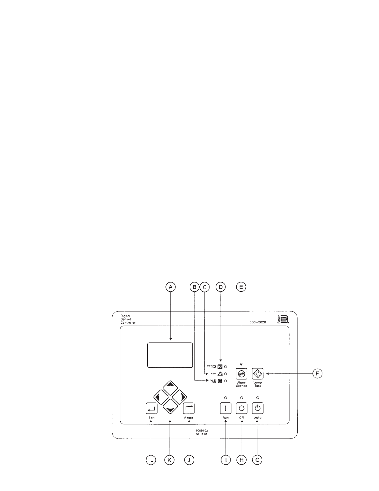
A - Liquid Crystal Display. The backlit, 64 by 128 pixel LCD
serves as the local information source for metering, alarms, prealarms and protective functions. Display operation is maintained
at -20°C. An optional LCD heater would maintain display operation at -40°C.
B - Not in Auto Indicator. This red LED lights when the DGC2020 is not operating in Auto mode.
C - Alarm Indicator. This red LED lights continuously during
alarm conditions and flashes during pre-alarm conditions.
D - Supplying Load Indicator. This green LED lights when the
generator current is greater than EPS threshold current.
E - Alarm Silence Push-button. Pressing this button opens the
relay output programmed as the horn output.
F - Lamp Test Push-button. Pressing this button tests the DGC2020 indicators by exercising all LCD pixels and lighting all LEDs.
G - Auto Push-button and Mode Indicator. Pressing the Auto
button places the DGC-2020 in Auto mode. The green Auto mode
LED lights when Auto mode is active.
H - Off Push-button and Mode Indicator. Pressing this button
places the DGC-2020 in Off mode. The red Off mode LED lights
when the DGC-2020 is in Off mode.
I - Run Push-button and Mode Indicator. Pressing this button
places the DGC-2020 in Run mode. The green Run mode LED
lights when Run mode is active.
J - Reset Push-button. This button is pressed to cancel a
settings editing session and discard any settings changes. When
pressed, this button also resets the Breaker Management PreAlarms
L - Edit Push-button. Pressing this button starts an editing
session and enables changes to the DGC-2020 settings. At the
conclusion of an editing session, the Edit push-button is pressed
again to save the setting changes.
DISPLAY OPERATION
The front panel display is used to make settings changes and
display metering values. Refer to call-outs J, K, and L in text and
illustration for information on changing settings through the front
panel and navigating through the Metering screens. When the
unit is first powered up, the clock may need to be reset. Editing
the clock provides familiarity with the edit process. All programming changes from the front panel are accessed through the edit
key to begin and exit the internal microprocessor program.
Log-in and Permissions
To Log-in, navigate to the SETTINGS, ENTER PASSWORD
screen and press the Edit key. Use the Up/Down arrow keys to
scroll through the characters. Use the Left/Right arrow keys to
enter more characters. The Owner operator password is OP.
Once the password has been entered, press the Edit key to Login. See the key stroke sequence listed below to access the
control and enter the edit mode. A LOGOUT selection now
appears in the list of SETTINGS. To logout, navigate to SETTINGS, LOGOUT and press the Edit key. The LOGOUT selection
is removed from the SETTINGS list.
Sequence for setting (or resetting) the system clock -
1) Press ‘K’ (right key) for initial set or ‘K’ (left to back up, up /
down) to choose menu item and time/date element to be
changed.
2) Press ‘L’ (Edit) to access change mode to enter Password OP as follows:
2a -Press K (up) to select O
2b -Press K (right) to move cursor
2c -Press K (up) to select P
2d -Press L (Edit) to begin change mode
3) Press ‘K’ (up or down) to choose year
4) Press ‘L’ (Edit) to enter year
5) Press ‘K’ (down) to select month mode
6) Press ‘L’ (Edit) to access month change
7) Press ‘K’ (up or down) to choose month
8) Press ‘L’ (Edit) to enter month
9) Repeat sequence 5 through 8 for day, minute, second and
DST (Daylight Saving Time).
To finish clock setting, process - Press ‘K’ (left).
K - Arrow Push-buttons. These four buttons are used to
navigate through the front panel display menus and modify
settings. The left- and right-arrow buttons are used to navigate
through the menu levels. The right arrow button is pressed to
60708-142
Page 5
8122-00

The microprocessor is still in the General Settings Edit mode.
Pressing ‘K’ (left) a second time exits the Edit mode and allows
full access to the View Only mode for all control settings and
current status. Any items to be changed are accessed by
pressing ‘K’ (up/down/right or left) to select, ‘L’ (Edit) to change
and ‘K’ (left) to exit.
Communication
Standard DGC-2020 communication features include a standard
USB port and SAE J1939 interface. Optional communication
features include a dial-out modem and RS-485 communication port.
The USB communication port can be used with BESTCOMSPlus
software to quickly configure a DGC-2020 with the desired settings
or retrieve metering values and event log records. The CANBus
interface provides high-speed communication between the DGC2020 and the engine control unit (ECU) on an electronically controlled engine. This interface provides access to oil pressure, coolant temperature, and engine speed data by reading these parameters directly from the ECU. When available, engine diagnostic data
can also be accessed. The CANBus interface supports the following protocols:
• SAE J1939 Protocol - Oil pressure, coolant temperature, and
engine speed data are received from the ECU. In addition, DTCs
(Diagnostic Trouble Codes) help diagnose any engine or related
failures. The engine DTCs are displayed on the front panel of the
DGC-2020 and may be obtained using BESTCOMSPlus software.
• MTU/MDEC Protocol - A DGC-2020 connected to a generator
Set equipped with an MTU MDEC receives Oil pressure, coolant
temperature, and engine speed data from the engine controller , along
with various alarms and pre-alarms that are MDEC specific. In addition, the DGC-2020 tracks and displays the active fault codes issued by the MDEC ECU.
Optional - Dial-Out Modem One of two optional, dial-out modems
(a US version or international version) enables remote control,
monitoring, and setting of the DGC-2020. When an alarm or prealarm condition occurs, the DGC-2020 can dial up to four telephone
numbers, in sequence, until an answer is received and the condition is annunciated.
ining the unit for damage during shipment. Avoid signing for the
equipment until a full visual assessment and inventory have been
made. Verify that you have received the right equipment and the
proper amount by matching up the equipment to the packing list.
Larger units may ship with the fuel tank and muffler removed. V erify
that those components are undamaged and removed from the truck
prior to their release.
The keys for doors of the enclosed generators sets are typically
attached to lifting eye on the base of the machine. These keys are
matched to all the doors on the generator set housing.
UNPACKING INSTRUCTIONS:
When unpacking the generator set, be sure to inspect it carefully for
freight loss or damage. If loss or damage is noted at the time of
delivery, require that the person making the delivery make note of
the loss or damage on the freight bill, or affix his signature under the
consignee’s memo of the loss or damage. Contact the carrier for
claim procedures.
When loss or damage is noted after delivery, segregate the damaged material, and contact the carrier for claim procedures.
“Concealed Damage” is understood to mean damage to the contents of a package which is not in evidence at the time of delivery by
the carrier, but which is discovered later. The carrier or carriers are
responsible for merchandise lost or damaged in transit. The title to
goods rests with the consignee when generators are shipped fob
factory, and only the consignee can legally file a claim.
***** CAUTION ****
EQUIPMENT DAMAGE - These units are shipped with oil,
and a 50/50 mix of coolant. Be sure to check all fluid
levels before operating. See engine manufacturer’s
instruction manual for recommended oil requirements
before initial starting.
UNPACKING:
(Not recommended until the unit is on-site)
Optional - RS-485 Port The RS-485 communication port uses the
Modbus communication protocol and enables remote control and
monitoring of the DGC-2020 over a polled network
.
RECEIVING THE GENERATOR
The generator set will generally be shipped by a commercial ‘common freight carrier’. Large and bulky units are often shipped on a
dedicated or specially contracted ‘Flat-Bed’ truck. The means of
shipment is determined in consultation between the WINPOWER
Sales and Shipping staff and the customer. Routing is determined
by the bulk, size, and a means available to unload the generator at
the receiving end. WINPOWER recommends units that are shipped
by common carrier be delivered to a commercial dock to allow the
Generator Set to be unloaded in a safe, efficient manner and to
minimize handling damage to the unit.
Locate the packing slip on the side of the crate or request it from
the truck driver. When receiving the unit take special care in exam-
8122-00
1. Carefully remove the crate.
2. After inspecting the engine-generator for external physical
damage, locate and check the following items packed with
the unit.
a. Owner’s operators manual.
b. Engine manufacturer’s instruction manual.
c. Battery hold-down brackets & hardware.
d. Unit components or accessory items shipped loose
for on-site installation.
e. Optional accessories (i.e. remote annunciator)
3. Remove main frame hold down bolts.
4. Unit can now be lifted from shipping rails.
Page 6
60708-142
LIFTING THE GENERATOR SET
NOTICE - Personal Injury
To prevent injury to persons or equipment, observe the following guidelines when lifting the generator:
Due to the different designs, configurations, options, weights, site
conditions, and available material handling equipment, specific lifting instructions are not provided for each individual generator set
model. General guidelines provided are applicable to the entire
standby generator line. It is the responsibility of the installing party
to follow the lifting equipment’s operators manual to prevent injury
to personnel and damage to the generator. Smaller Generator Sets
may not require use of overhead lifting equipment and may be placed
on the pad with basic material handling equipment, i.e. a forklift.
CAUTION: - Do not attempt to lift the generator set by the means
of the lifting eyes on the engine or generator end.
These lifting points are only for use during the manufacturing process and are designed for lifting of the individual Generator Set
component.
WINPOWER has designed all of its Generators Sets to be lifted at
the corners with an appropriate lifting rig. The lifting points are
located on the side rails of the generator base or on the optional
base mounted fuel tank of a Diesel Generator Set.
The generator set can be lifted with properly rated chains or cables
along with the use of spreader bars. The spreader bars should be
long enough so that the lift cables or chains do not come into contact with the generator set. Use of commercially available lifting
fixtures may also be used. Always be sure that the equipment is
properly rated for the weight of the generator. Failure to do so can
cause damage to the generator, injury to personnel or even death.
The generator set and fuel tank may or may not be shipped as a
complete unit. If the fuel tank is shipped separate from the generator, place the tank on the cement pad first, and then place the generator on top of the fuel tank.
***************
***** WARNING ****
***************
NEVER - attempt to lift the fuel tank while filled with fuel. Sloshing of the fuel can cause a shift in the balance of the fuel tank,
making for a DANGEROUS, unbalanced lifting load. If the generator was shipped on the fuel tank, use the lifting points located on the fuel tank to move the entire Generator Set into
place. DO NOT place fuel in the tank prior to lifting.
Depending on generator set size and configuration, the exhaust
system may ‘ship loose’ with the generator set for installation on
site. The muffler and its attaching brackets must be mounted on
top of the generator housing prior to operating the engine
generator set.
INSTALLATION
60708-142
Page 7
8122-00

***************
***** WARNING ****
***************
PERSONAL INJURY - Before proceeding with the installation,
be sure the DGC-2020 is in the "stop" position. Before
proceeding with the installation, be sure the Generator MLCB
(Main Line Circuit Breaker) is in the ‘OFF’ position and the
unit starting battery is disconnected.
FUEL INSTALLATION
The fuel supply should be as close to the engine as possible. This
will reduce the installation cost of fuel runs and minimize line losses.
The diesel fuel supply should be no more than 3 feet below the fuel
inlet on the pump. If your fuel supply is lower than three feet you may
have to install an additional lift pump to bring the fuel up to the
mechanical fuel pump on the engine.
GENERAL INFORMATION
These engine/generator sets are generally supplied as weather
enclosed packages for quick installation on an outdoor concrete
pad. They are also available as open skid mounted units for indoor
installation in a building or protective enclosure supplied by the
installer. The factory weather enclosures are available as standard
or acoustical housing intended for outdoor installation only. Factory
weather enclosed units are not intended to be used indoors and
no support is available to assist in re-engineering finished
packaged units.
All versions must be bolted to a solid base for proper operation. A
properly designed concrete pad is necessary for stationary operation. A substantial DOT certified trailer is required for mobile applications. Consult a qualified, licensed electrician or contractor to
install and wire this Generator Set. The installation must comply
with all national, state, and local codes.
Before beginning the installation process, recheck the voltage,
phase and amperage rating of the Generator Set and ATS (Automatic Transfer Switch). Be certain they can handle the intended load
and are compatible with the entrance voltage, phase and current
ratings. Plans for installation should be prepared with proper
attention to mechanical and electrical engineering detail to assure a
satisfactory system installation.
The information in this manual is offered only as a guide to finalizing
your installation plans.
The information in this manual is offered to assist you in providing the
proper fuel for your engine. However, this information is only provided to inform you of the engine’s requirements and assist in
making you aware of the decisions you must make. In no case
should the instructions or information provided be interpreted to
conflict with any local, state or national codes. If in doubt, always
consult your local fire marshal or fuel supplier.
INSTALLING THE FUEL LINE
Engine generator sets are properly adjusted before they leave the
factory. Connecting a fuel supply with adequate supply volume is
critical to reliable operation. Diesel units with optional base mounted
fuel tanks are pre-plumbed to the mechanical fuel pump on the
engine.
Open skid mounted Diesel units are often supplied with capped inlet
and return lines. The use of a suitable customer supplied flexible fuel
line is essential between the engine and fuel supply to provide a
vibration break between your fuel supply and the engine.
***************
***** WARNING ****
***************
FIRE DANGER - Connecting rigid fuel line (i.e. steel or copper
line) directly to the inlet fuel filter or fuel pump may cause the
fuel line to crack during operation creating a serious fire
hazard.
NOTICE
For full service switching of the entire load, the ATS must be ‘SE’
(Service Entrance) rated or must have a properly rated fusible
disconnect installed before the ATS to protect the contacts.
.
ENGINE GENERATOR SET MOUNTING
The unit’s main frame must be bolted solidly to a 4 to 6 inch thick
cement pad. The engine-generator is mounted on a sub-frame
which is attached with special shock mounts to the main frame.
This allows the engine-generator free movement without affecting
the control panel which is mounted on the main frame.
Do not shock mount the main frame. Engine vibration will be
transmitted to the control panel causing erroneous start/stop
cycles and premature control failure.
The unit should be mounted to allow for ample working room
around it. A general rule to follow is five (5) feet of clearance on
all sides. (Code NFPA 37)
8122-00
LUBRICATION
Before starting the engine, check the oil level in the crankcase. If
it is low, refill to the full mark with the proper weight/grade of oil as
recommended by the engine manufacturer’s maintenance
instructions. The necessity of using the correct oil, and keeping
the crankcase full cannot be over emphasized. Failure to use the
proper oil and keep the crankcase properly filled will cause
excessive engine wear and shorten its useful life.
COOLANT
Before starting the engine, check the coolant level in the radiator.
If it is low, refill as specified in the engine manufacturer’s maintenance instructions. The radiator should be filled to about 1 inch
below the filler neck. For additional information on engine coolant
requirements see engine manufacturer’s maintenance instructions.
Page 8
60708-142
 Loading...