

Winpower Arc Welder User Manual
x?!t
W
INPOWER
CORPORATION
175
AMP
Dm
Cm
PART I BELT
AND
PULLEY
Preliminary 'Check
1.
Check for broken belt.
2.
check for .slipping belt or slipping
pulley.
If the belt or a1:crnator pulley
is
slipping, the
arc will start strong and die away as the alternator-slows down.
It
will be noticeable at high
amp settings. The belt should be tight and have
very little "give" when checked by hand after removing the belt screen. (Fig.
1-1)
Caution - Replace screen before starting the
welder engine.
Note - The belt will burn (melt) and be ruined
if allowed to slip for any length of time.
Pulle-; Alignment and Belt Tension
If belt breaks, turns over or jumps out of the
grooves after a short period of time, or does not
last when replaced, THERE IS
SO?!ETHING WRONG WITH
EITHER THE
ALIGWENT OR THE TENSION OF THE BELT.
It
will do no good to replace the belt without
correcting the problem.
SYMPTOMS PROBABLE CAUSE
7--
Belt burns, melts or has
small cracks on inside. Belt too loose.
Belt breaks with clean break. Belt too tight.
Belt breaks along one edge, Belt not in
jumps out of'groove or turns
alignment or too
over in groove. tight.
Burr on Pulley
CORRECT BELT ALIGNMENT
AND
PROPER TENSION
is
cru-
cial to belt life.
ELARE SURE BELT IS ALIGNED.
The belt should be checked for tightness after a
few hours of operation of a new machine.
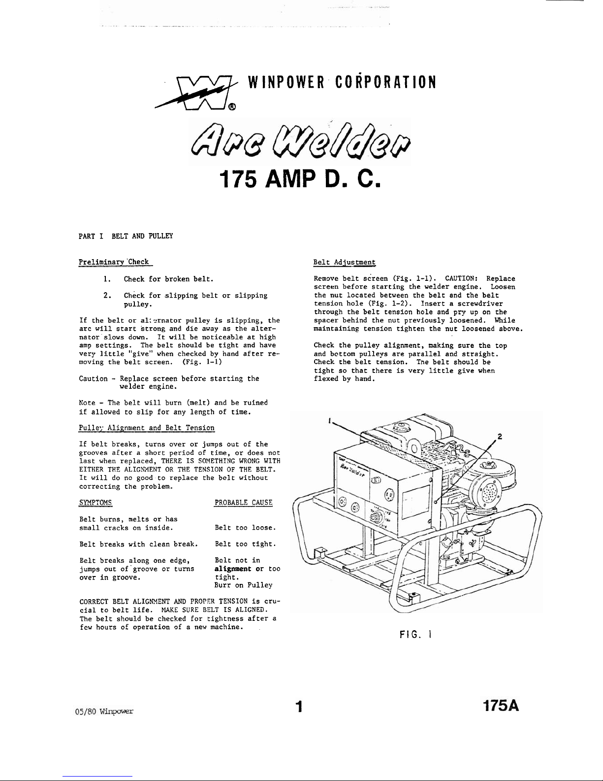
Belt Adjustment
Remove belt screen (Fig. 1-1). CAUTION: Replace
screen before starting the welder engine. Loosen
the nut located between the belt and the belt
tension hole
(Fig.
1-2). Insert a screwdriver
through the belt tension hole and pry up on the
spacer behind the nut previously loosened. While
maintaining tension tighten the nut loosened above.
Check the pulley alignment,
making sure the top
and bcttom pulleys are parallel and straight.
Check the belt tension. The belt should be
tight so that there
is
very little give when
flexed by hand.
FIG.
I
Pulley Removal
To remove the alternator pulley, remove the nut
and lockwasher, apply even pressure to the pulley
with a screwdriver and
heat with a propane torch
_
until the Loctite loosens and the pulley will
slip off.
Note:
Trying to remove the pulley without heat
will damage
it.
Both alternator and engine pulley
must have Loctite to keep them from slipping.
Use
high strength Loctite, Cat. No. 271-41. Use
instructions supplied with the Loctite.
To remove the engine pulley, clean the shaft of
dirt and rust in front of the pulley, apply pressure to the pulley with a
wheel puller and a~ply
heat to the pulley until the Loctite loosens and
the pulley will slip off.
Note:
Trying to re-
move with
a
wheel puller without heat xi11 bed
the pulley.
PART
I1
DETER4INE THE FAILIYC UWIT
Engine Lugs Down
If the engine powering a Winpower welder "lugs down"
this indicates an engine problem,
not
a
welder
problem. The problem
is
simply that the welder
is
calling for more power than the engine can
supply and the
RRl's
drop. If a lugging condition occurs, more output can be obtained by turning the current adjustment knob
down
to a lower
setting so the engine
RP?I1s do not drop.
NOTE: A drop in output and engine lug can occur
because of an
uncuned or worn engine, high
altitude or extreaely hot days that cause a reduction
in engine power. (There
is
a 1I drop for each 10
degrees
F
above 60 degrees F and
a
3%
drop for
each
1000 feet above sea level. Contact engine
manufacturer for further details.)
Lov Open Circuit Vnltage-
The open circuit voltage
will
be low if the en-
gine
is
not running Pull speed (3600 RPPl's).
Measure
the open circuit voltage at the
weldizg
receptacles with the engise running full speed,
not welding, no accessory power being used, and
the current adjustment knob setting at 175
amns.
Three Circuits
The alternator on the Winpower welder has three
separate circuits.
1. Control Circuit
2. Welder Circuit
3. Accessory
Circl~it
All three of these circuits have their own individual winding and are not connected electrically
to each other.
-.
Exciter Check
If the unit
is
completely dead, suspect excitation
problems, especially
.if
:he
unit hns heen sitting
unused for a long
time.
Check the exciter wire
connection at the engine and insure
the exciter
wire
is
not loose, broken or shorted to the frame.
The welder should be running full speed with the
knob setting at
17%.
Voltage Check to determine failing circuit
By
using the following procedure and examples before removing the shroud, the failing circuit can
normally be determined
(i.z.
welder, accessory,
or control).
If the welder comes to you removed
from thc engine and no ex?lanation of the problem,
the
checkout procedure in later parts of this book
will still Find the problem.
IT
the welder
is
puttin:; out anytlling at all, mea-
sllrc the I1.C. onen circuit voltage of both the
r~elder and accessory.
iiieldrr should be approxi-
mately 70
V.D.C.
and the accessory should be about
125
V.11.C.
>leasure with knob set at maximum amps.
SEFOHE C!IECKIXC VOLTAGE
TO
DETEY.ITNE FAILISG UNIT
iiAKE SURE
PKOBLM
IS HOT LO:.' ENGINE PGVER, LOW
ENGINE RPM's, OR EXCITER PROBLEM.
Examnle I Unit conpletely dead, no welder or
accessory voltzge. Problem
is
in the
control circuit.
Examnle 2 Low voltage outnut. The maximum open
--
circuit voltage welder
is
measured at
45
volts, (should he 70), and maximum
open circuit voltage accessory
is
74
volts, (should be 125).
Tlie problem
is
in the control circuit.
Exanple 3 Low current outpuc . !laximum weider
--
open circuit voltage
is
73, (o.k.),
and maximumaccessory open circuit
voLtage
is
122 (0.k.). Again, pro-
blem
is
in thc control circuit.
Example 4 No welder output. Welder own circuit
voltage zero (should be
70).
Accessory
open circuit voltage 120 (0.k.). Problem
is
in the welder circuit.
Sxample 5 Low welder output. Yaximl~m welder open
circuit voltage
is
48 (should be 70).
Xaximum accessory open circuit voltage
is
120 (0.k.). Problem
is
not
in the
control circuit, but in the welder
circuit.
Example 6 No accessory output. Welder open cir-
cuit voltage 70
(0.k.). Accessory open
circuit voltage zero (should be 125).
Problem
is
in accessory circuit.
Example 7 Low accessory output. Welder open cir-
cuit voltage
is
74 (0.k.). Accessory
open circuit voltage
is
80
(should be
125).
Problem
is
not
in the concrol
circuit but
is
in accessory circuit.
Note - If problem
is
in the accessory circuit;
-
check the 4 fuses
(1
on panel and 3 under thc
sllroud). Tlli. fl~scs affect only the L20V accessory.
PART
I11
CONTROL CIRCUIT MINTENANCE Ccrnponent T'esting
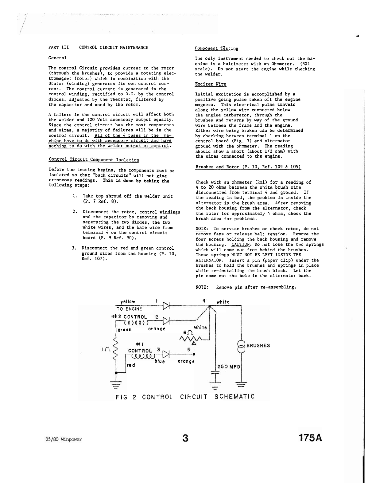
General
The control Circuit provides current to the rotor
(through the brushes), to provide a rotating electromagnet (rotor) which in combination with the
Stator
(winding) generates
its
own control cur-
rent. The control current
is
generated in the
control winding, rectified to D.C. by the control
diodes, adjusted by the rheostat, filtered by
the capacitor and used by
the rotor.
A
failure in the control circuit will affect both
the welder and 120 Volt accessory output equally.
Since the control circuit has the most components
and wires, a majority of failures will be in the
control circuit.
All
of the 4 fuses in the ma-
chine have to do with accessorv circuit and have
nothing to do with the welder output or
co11trol.
The only instrument needed
to
check out the ma-
chine
is
a
Multimeter with an Ohmmeter.
(RX1
scale). Do not start the engine while ciircking
the welder.
Exciter Wire
Initial excitation
is
accomplished by a
positive going pulse taken off the engine
magneto. This electrical pulse travels
along the yellow wire connected below
the engine carburetor, through the
brushes and returns by way of the ground
wire between the frame and the engine.
Either wire being broken can be determined
by checking between terminal
1
on the
control board (Fig.
3)
and alternator
ground
with the ohmmeter. The reading
should show a short (about 1/2 ohm) with
the wires connected to the engine.
Control Circuit Component Isolation
Brushes and Rotor (P. 10, Ref. 109 & 105)
Before the testing begins, the components must be
isolated so that "back circuits" will not give
erroneous readings.
This
is
done by taking the
Check with an ohmmeter (Rxl) for a reading of
following steps:
4
to 20 ohms between the white brush wire
1.
Take top shroud off the welder unit
(P.
7
Ref.
8).
2.
Disconnect the rotor, control windings
and the capacitor by removing and
separating the two diodes, the two
white wires, and the bare wire from
ter~tinal 4 on the control circuit
board
(P. 9 Ref. 90).
3.
Disconnect the red and green control
grcund wires from the housing
(P. 10.
Ref.
107).
disconnected from terminal 4 and ground. If
the reading
is
bad, the problem
is
inside the
alternator in the brush area. After removing
the back housing from the alternator, check
the rotor for approximately
4
ohms, check the
brush area for problems.
NOTE: To service brushes or check rotor, do not
remove fans or release belt tension. Remove the
four screws holding the back housing and
remove
the housing. CAUTION: Do not lose the two springs
which
will
come
04:
from behind the brushes.
These springs
MUST
NOT
BE
LEFT INSIDE THE
ALTERNATOR. Insert a pin (paper clip) under
the
brushes to hold the brushes and springs in place
while re-installing the brush block. Let the
pin come out the hole in the alternator back.
NO'TE:
Reiaove pin after re-assembung
.
yellow
I
,,,
4'
white
TO
EKGINE
L/1
1
#
2
CONTROL
green
orange
white
6fl
blue
orange
red
FIG. 2
CONTROL
CIhCUIT
SC
 Loading...