

Page 1
Page 2

1 /
Contents
1. OVERVIEW ................................................................................................................... 2
2. PRODUCT PARAMETER ............................................................................................... 3
3. PRODUCT STRUCTURE AND SPARES ......................................................................... 3
4. JUDGEMENT OF MAINBOARD SIGNAL AND CONNECTION ........................................ 4
4.1. CONVERTER BOARD C1 ........................................................................................................ 4
4.2. CONVERTER BOARD C2 ........................................................................................................ 5
4.3. CONVERTER BOARD C3 ........................................................................................................ 7
4.4. CONVERTER BOARD C4 ........................................................................................................ 8
4.5. CONVERTER BOARD C5 AND C6 ............................................................................................ 9
4.6. CONVERTER BOARD C7 AND C8 .......................................................................................... 10
4.7. CONVERTER BOARD CD/S1 (FOR SAMSUNG USIT 96PIN SINGLE LCD MODULE CABLE
SEQUENCE) .................................................................................................................................. 13
4.8. CONVERTER BOARD S3 (FOR SAMSUNG USIT 96PIN DUAL LCD MODULE CABLE SEQUENCE).... 14
4.9. CONVERTER BOARD V1 (FOR 4K-VBYONE CABLE SEQUENCE) ............................................. 15
5. USER GUIDE.................................................................................................................16
5.1. MAIN INTERFACE DESCRIPTION .............................................................................................. 16
5.2. CONNECTION INSTRUCTION ................................................................................................... 16
5.3. TESTING AND OPERATION...................................................................................................... 17
5.3.1. Enter and exit the menu interface .............................................................................. 17
5.3.2. Number of signal lanes ............................................................................................... 18
5.3.3. Color Mode ................................................................................................................. 18
5.3.4. Color bits .................................................................................................................... 18
5.3.5. Screen Division ............................................................................................................ 19
5.3.6. Display Mode .............................................................................................................. 19
5.3.7. Image Adjustment ...................................................................................................... 20
6. PRECIOUS POINTS ......................................................................................................20
7. APPENDIX ONE ...........................................................................................................22
8. APPENDIX TWO ..........................................................................................................22
9. APPENDIX THREE .......................................................................................................23
Page 3

2 / 27
EXV9210
1. Overview
For various flat panel display technologies, TFT-LCD (Thin Film Transistor-Liquid Crystal
Display) technology dominates the flat panel display market due to its low operating voltage,
low power consumption, long life, no radiation and low cost characteristics. The driving system
of the TFT-LCD panel consists of a gate driver GD (Gate Driver), a source driver SD (Source
Driver) and a timing controller T-CON (Timing Controller). The T-CON converts the sync control
signal and data signal received from the signal source to specific input signals required by the
GD and SD respectively, and sends the data signal to each SD through the interface protocol. As
the mainstream display technology, TFT-LCD is developing towards a large screen, high
resolution and high color depth, resulting in a dramatic increase in the amount of transmission
data . The performance of the interface protocol is directly related to quality of the display.
Therefore, for various TFT-LCD display technologies, the interface protocol is the key point to
determine whether the data signal between T-CON and SD can be transmitted correctly.
In response to market demand, the interface protocol has developed for three
generations. The first generation uses TTL or CMOS levels to transfer data in parallel. The
second-generation interface protocol adopts a multi-drop bus structure of low-swing
differential signaling and serial transmission. The third-generation interface protocol uses a
point-to-point architecture, the P2P architecture, where the T-CON and each SD are
transmitted by separate differential data pairs. In addition to retaining the advantages of the
second-generation interface protocol, the point-to-point structure greatly reduces the number
of transmission lines, and the signal line impedance is not affected by SD loading. These
advantages ensure data transmission stable and reliable based on the point-to-point interface
protocol, and they support large-size, high-speed, high-resolution, and high-color depth TFTLCD.
EXV9210 is a P2P signal converter, which can convert P2P signal to HDMI signal, or directly
display the signal image. At present, there are many types of P2P signals on the market
including CSPI, CEDS, iSP, EPI, etc. EXV9210 can directly convert these P2P signals into image
signals for display on a 5-inch screen, or convert these signals into HDMI signals on external
display. EXV9210 makes production testing and after-sales maintenance easy and fast.
EXV9210 support stand-alone debugging function. If you use this function, you should first
exit PC debugging function and then press “RESET” button in tester device. After that,you can
use tester device buttons to debug functions you need. While you use PC debugging function,
all tester device buttons will be invalid.EXV9210 support English version menu.
Note: EXV9210 can communication with PC by USB or RS232 interface to fulfill FCT function
(
More details , you can review EXV9210 user guide).
Page 4
3 / 27
EXV9210
2. Product Parameter
Item
Parameter
Products Name
P2P signal Converter device
Model
EXV9210
Input Power
5V/5A
LCD size
5 inches
Input Signal type
USIT----of Samsung
CSPI----of CSOT
CEDS----of BOE
ISP----of AUO
EPI----of LG
V-by-One
Output signal type
HDMI/1080P
Product size
170*120*33mm
Warranty
1 year
3. product structure and spares
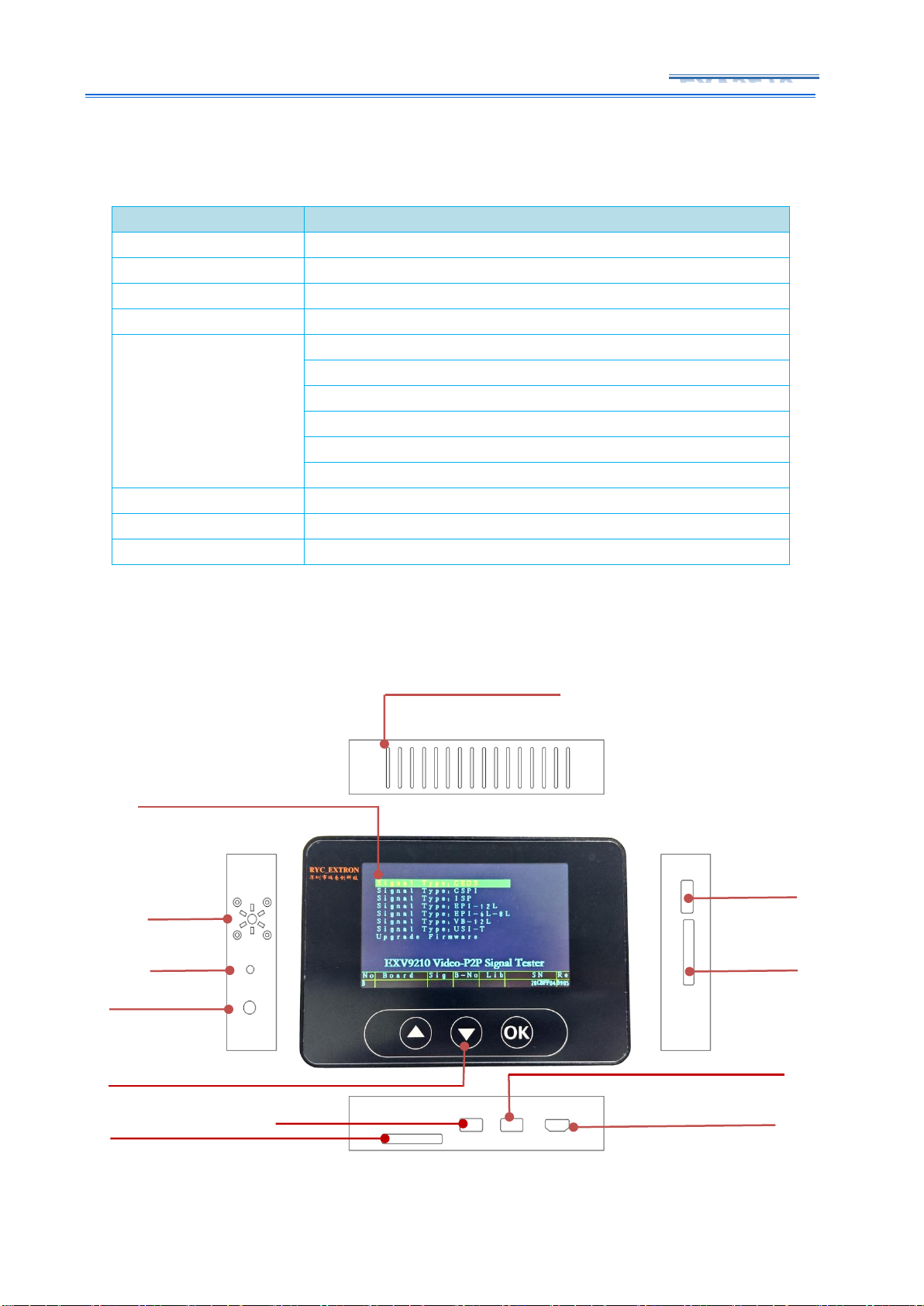
Heat Dissipation Hole
5 inches LCD module
Fan
Reset
Power Input
Reserve
Link port
Touch button
USB2
USB1
HDMI output
Signal Input
Page 5
4 / 27
EXV9210
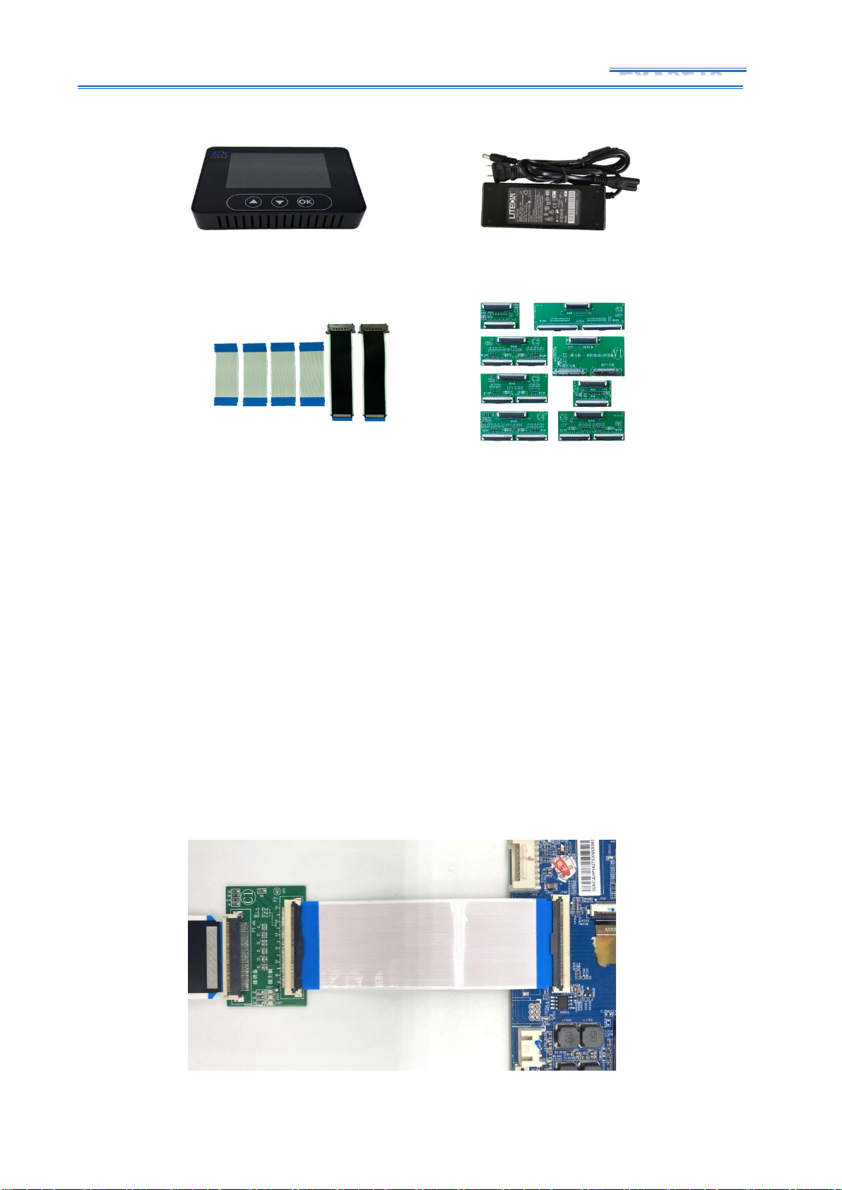
Figure 3-1 EXV9210 Structure
Figure 3-2 EXV9210 Standard Product and spares List
4. Judgement of mainboard signal and Connection
4.1. Converter board C1
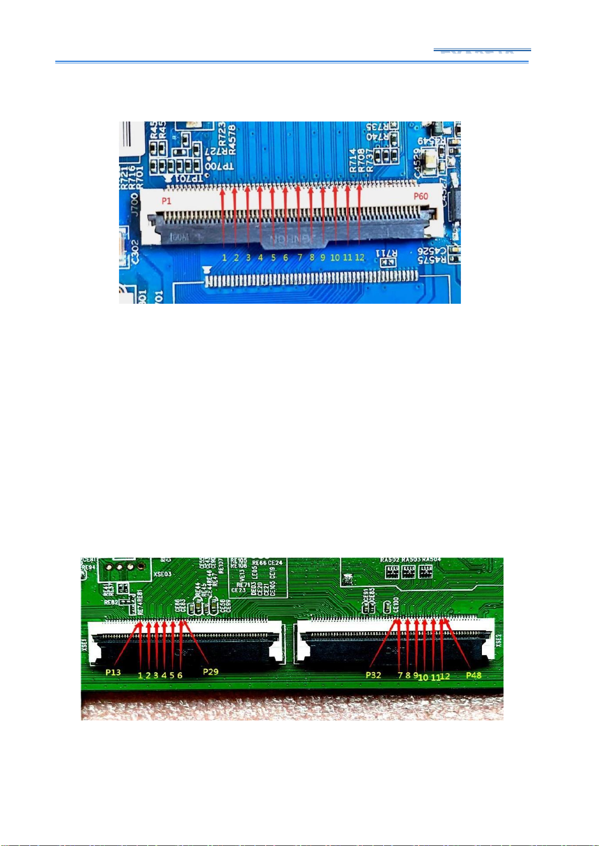
The P2P signal is generally 12 pairs of differential signal cables, and a few special
motherboards contain 8 pairs or 6 pairs of differential signal cables, they are including 60 Pin
single LCD module cables and 60Pin dual LCD module cables. For the 60Pin single LCD module
cable sequence, there are 12 pairs of differential signal cables, each pair of differential signal
cables is separated by a ground line, as shown in Figure 4-1-1, P13-P47 are differential signal
cables, and differential cables It is separated by ground wire, and the wire sequence is tested by
converter board C1, as shown in Figure 4-1-2 .
Host*1
5V*5A power*1
FFC Flat cable*6
Converter Board*8
Page 6
5 / 27
EXV9210
Figure 4-1-1 60Pin Single LCD module cable P2P sequence
Figure 4-1-2 Converter board C1 Connection
4.2. Converter Board C2
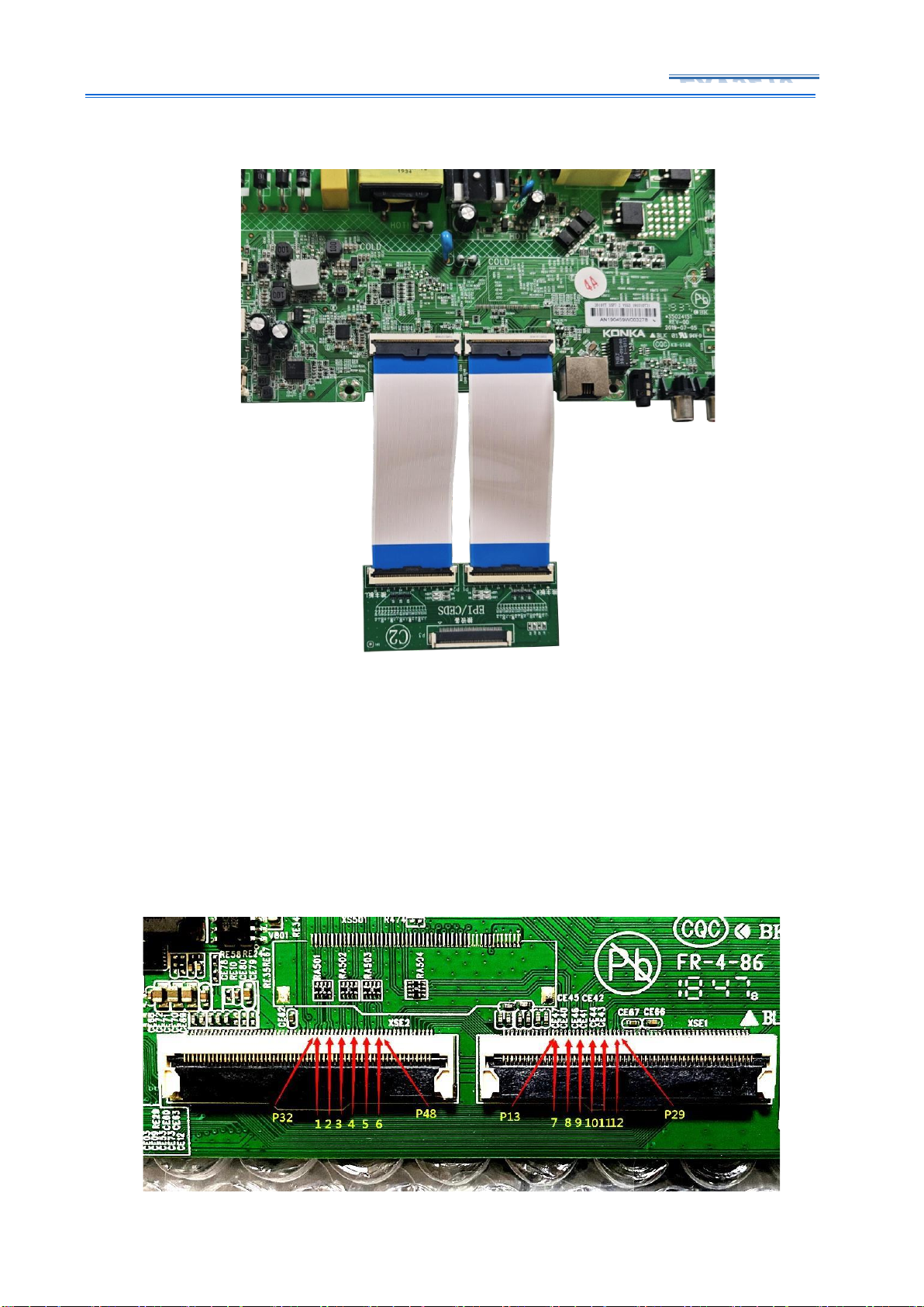
The P2P signal of the 60Pin dual LCD module cable is more complicated. During the test, the
pin position of the differential cable must be in one-to-one correspondence with the converter
board, and cannot connect incorrectly. As shown in Figure 4-2-1, for 60Pin dua LCD module
cable P2P signal, each LCD module cable contains 6 pairs of differential signal cables, and each
pair of differential signal cable is separated by a ground wire. Among them, the left LCD module
cable P13-P29, the right LCD module cable P32-P48 is the position of the differential signal line,
the line sequence is connected to the C2 converter board, as shown in Figure 4-2-2.
Figure 4-2-1 60Pin Dual LCD module cable P2P sequence
Page 7
6 / 27
EXV9210
Figure 4-2-2 Converter Board C2 Connection
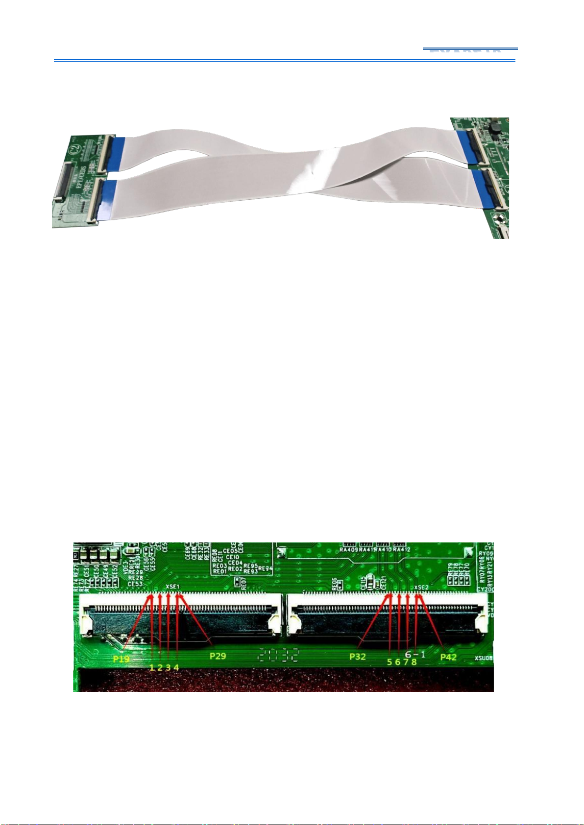
There is a P2P motherboard with the same cable sequence as converter board C2, but the
two 60Pin sockets are placed in opposite directions, and the cable sequence is as shown in
Figure 4-2-3, the left LCD module cable P32-P48, the right LCD module cable P13-P29 are the
positions of the differential signal lines. When testing the mainboard of this cable sequence,
you need only cross the LCD module cable and insert them into converter board C2, as shown
in Figure 4-2-4
Page 8
7 / 27
EXV9210
Figure 4-2-3 60Pin Dual LCD module cable P2P sequence
-
Figure 4-2-4 Converter Board C2 Connection
4.3. Converter Board C3
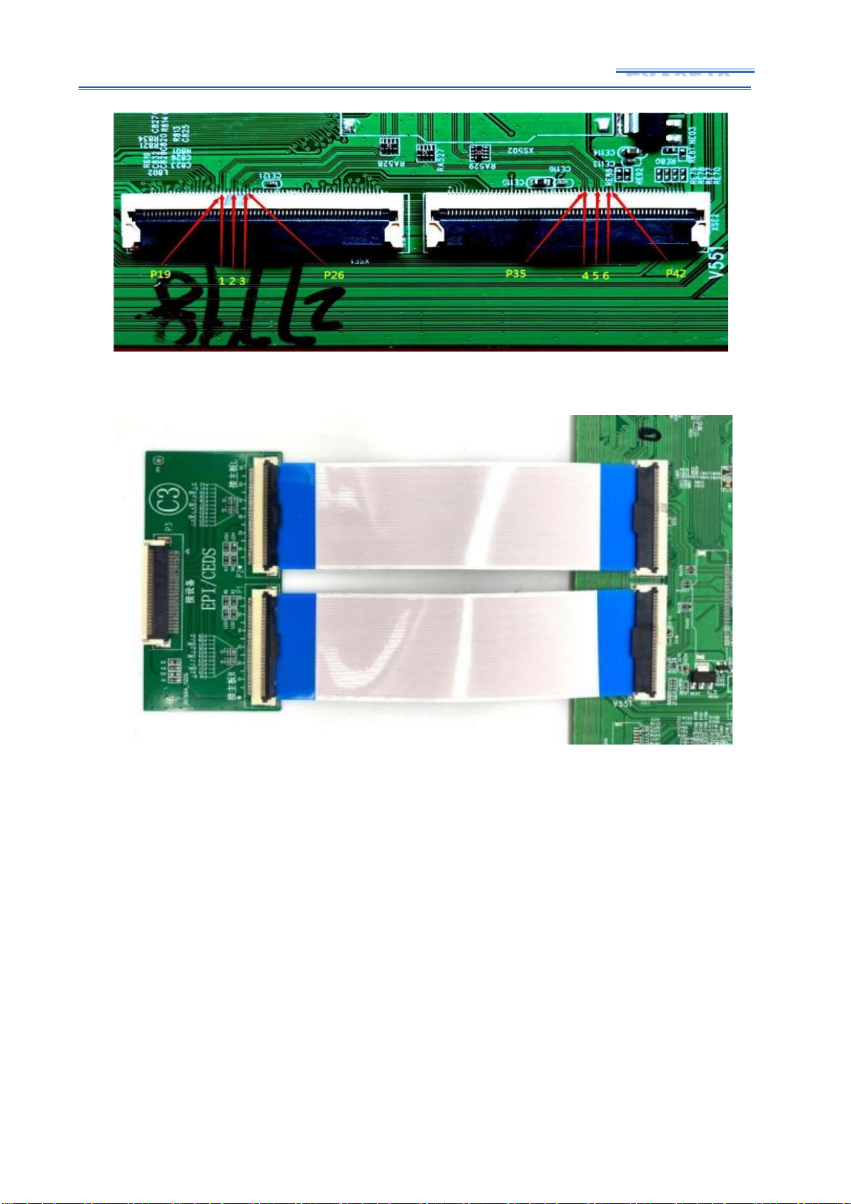
In addition to the 12 pairs of differential signals, there are also 8 pairs or 6 pairs of 60
Pin dual LCD module cable P2P signals, and the left and right sockets respectively contain 4
pairs or 3 pairs of differential signal lines. As shown in Figure 4-3-1, the left screen line P19P29 of the 8 pairs of differential signal lines and the right LCD module cable P32-42 are the
positions of the differential signal cable and each pair of differential signal cables is separated
by a ground wire. The cable sequence of the 6 pairs of differential signal lines, the left screen
line P19-P26, the right screen line P35-42 is the position of the differential signal line, which is
the same as the 8 pairs of differential signal lines, except that there is one pair of differential
signal lines on the left and right sides, and the positions are the same. are the same, as shown
in Figure 4-3-2. These two line sequences can be tested with the same converterboard C3, as
shown in Figure 4-3-3.
Figure 4-3-1 60Pin Dual LCD module cable P2P sequence
Page 9
8 / 27
EXV9210
Figure 4-3-2 60Pin Dual LCD module cable P2P sequence
Figure 4-3-3 Converter board C3 Connection
4.4. Converter Board C4
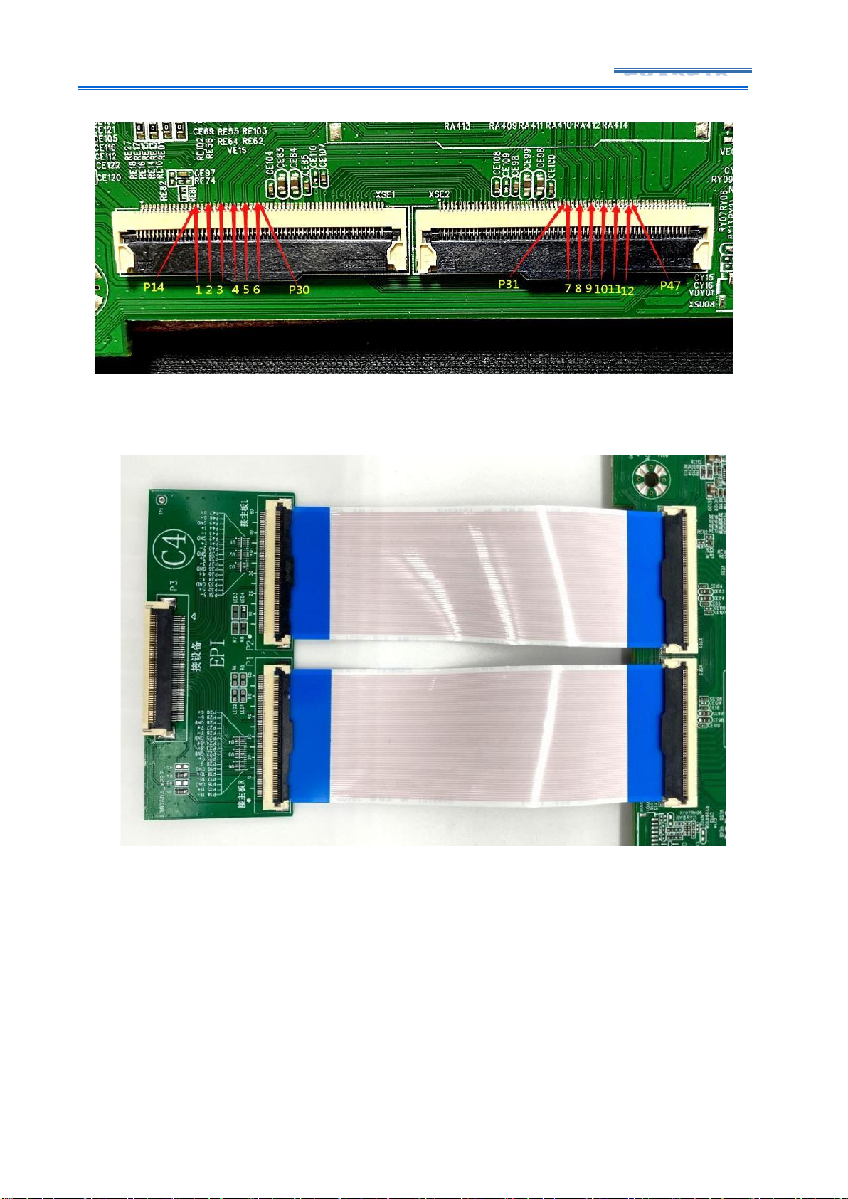
Among these 60Pin dual LCD module cable P2P signals, there is a cable sequence that is
very similar to the cable sequence corresponding to Converter board C2, so you must pay
attention and distinguish one from another when testing. As shown in Figure 4-4-1, the P2P
signal cable sequence of 60Pindual LCD module cables, the left LCD module cable P14-P30, and
the right LCD module cable P31-P47 are the positions of the differential signal cables.
Compared with the corresponding line sequence of the converter board C2, only One foot was
staggered. When testing the P2P signal of this cable sequence, it is necessary to connect the
converter board C4 for testing, as shown in Figure 4-4-2. Since the cable sequences of the two
converter boards are very similar, during the test, we must pay attention to distinguish it from
the C2 converterboard.
Page 10
9 / 27
EXV9210
Figure 4-4-1 60Pin Dual LCD module cable P2P sequence
Figure 4-4-2 converter board C4 Connection
4.5. Converter Board C5 and C6
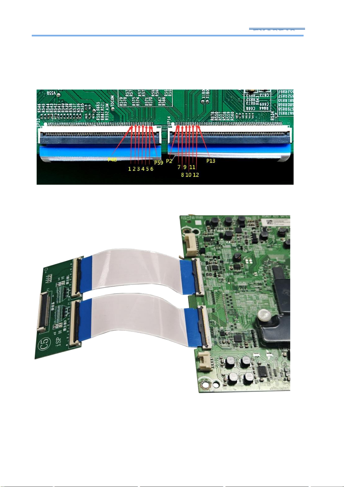
There is also a line sequence for the P2P signal of 60Pin dual LCD module cable, which
includes 12 pairs of differential cable either, but the differential signal cables are not directly
separated by ground lines, as shown in Figure 4-5-1, the left LCD module cable P48-P59, The
right LCD module cable P2-P13 is the position of the differential signal cable. Judging from the
position of the differential signal cable, this cable sequence corresponds to following two
Page 11
10 / 27
EXV9210
converter boards: C5 and C6. Among them, C5 corresponds to the iSP signal, and C6
corresponds to the CSPI signal. You need choose suitable boards according to the schematic
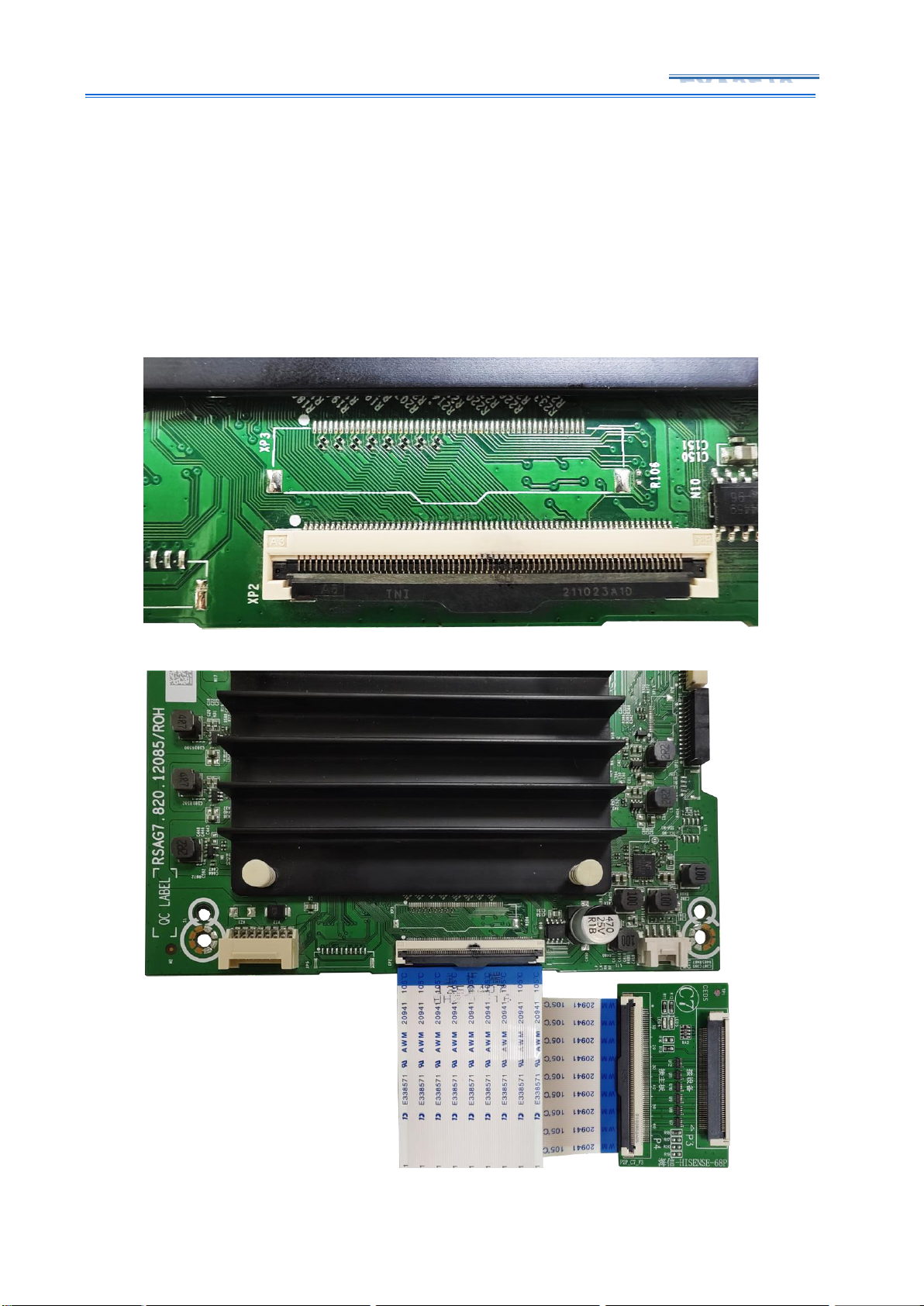
diagram when testing. As shown in Figure 4-5-2, it is the wiring diagram of the iSP signal main
board. The iSP signal is connected to the C5 converterboard.
Figure 4-5-1 60Pin Dual LCD module cable P2P sequence
Figure 4-5-2 Converter Board C5 Connection
4.6. Converter board C7 and C8
P2P signal 68Pin single LCDmodule cable sequence include Hisense 68P and Skyworth 68P
two cable sequences, corresponding to C7 and C8 two converter boards respectively. The
Page 12
11 / 27
EXV9210
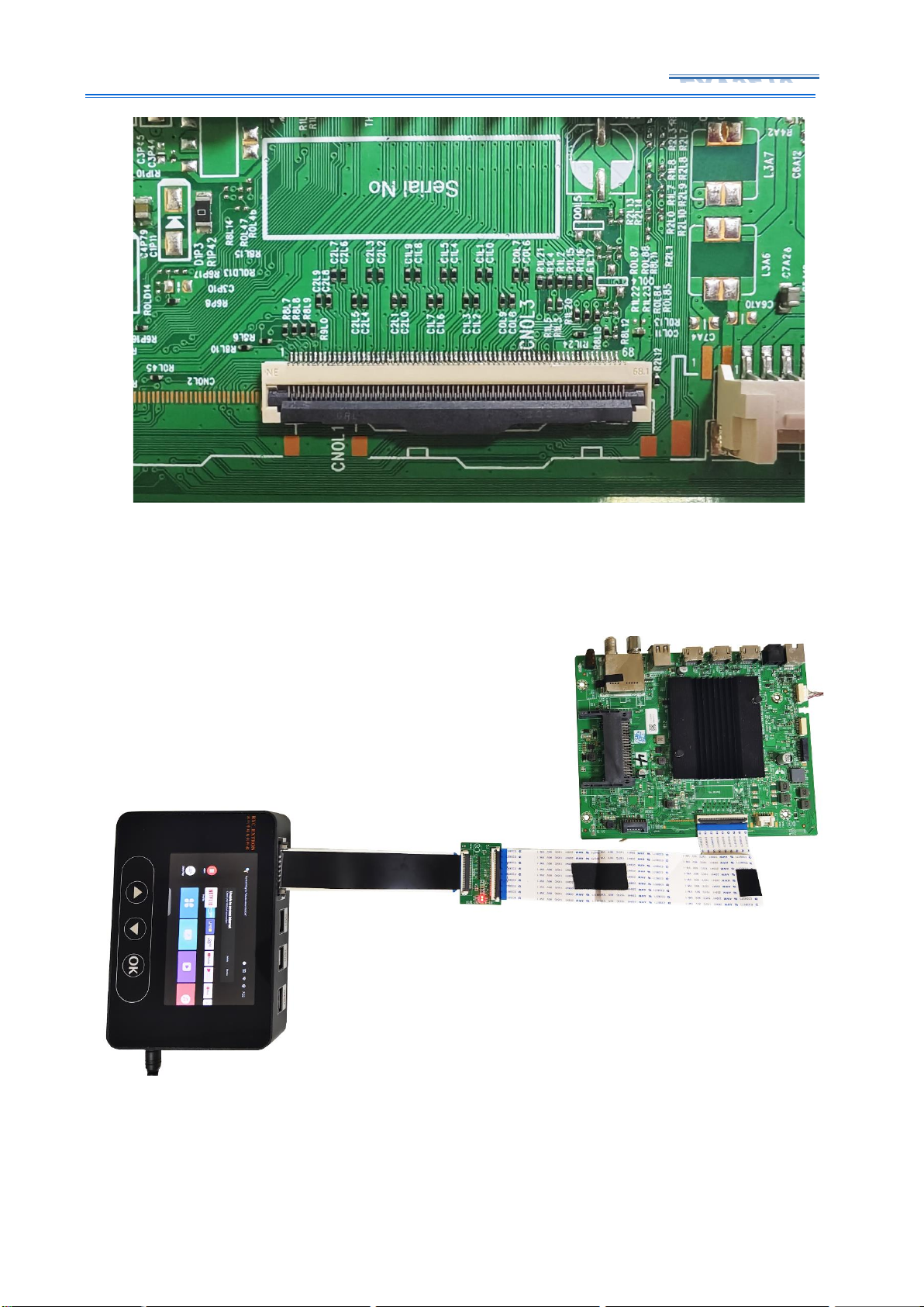
position and number of differential signal cables of these two cable sequences are all 12 pairs
of differential signal cables, each pair of differential signal cable are separated by ground wire.
Converter board can be determined by the schematic diagram, P2P motherboard statistics or
consulting engineers. Hisense 68Pin shown in Figure 4-6-1, P9-P43 are all differential signal
cables, which are separated by ground wire. This cable sequence can be tested by C7 converter
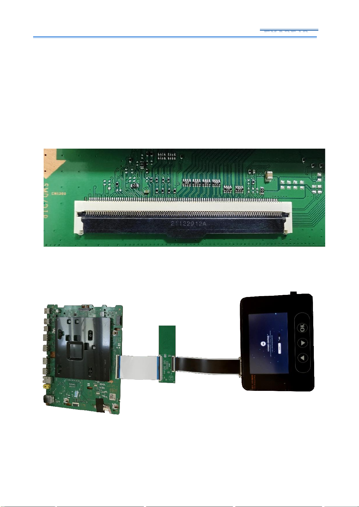
board shown in Figure 4-6-2. Skyworth 68Pin shown in Figure 4-6-3, P9-P43 are differential
signal cables, the differential cable are separated by ground wire, the cable sequence can be
tested with converter board C8 shown in Figure 4-6-4.
Figure 4-6-1 Hisense 68Pin
Figure 4-6-2 Hisense 68Pin C7 connection
Page 13
12 / 27
EXV9210
Figure 4-6-3 Skyworth 68Pin
Figure 4-6-4 Skyworth 68Pin C8 connection
Page 14
13 / 27
EXV9210
4.7. Converter board CD/S1 (for Samsung USIT 96Pin single LCD module
cable sequence)
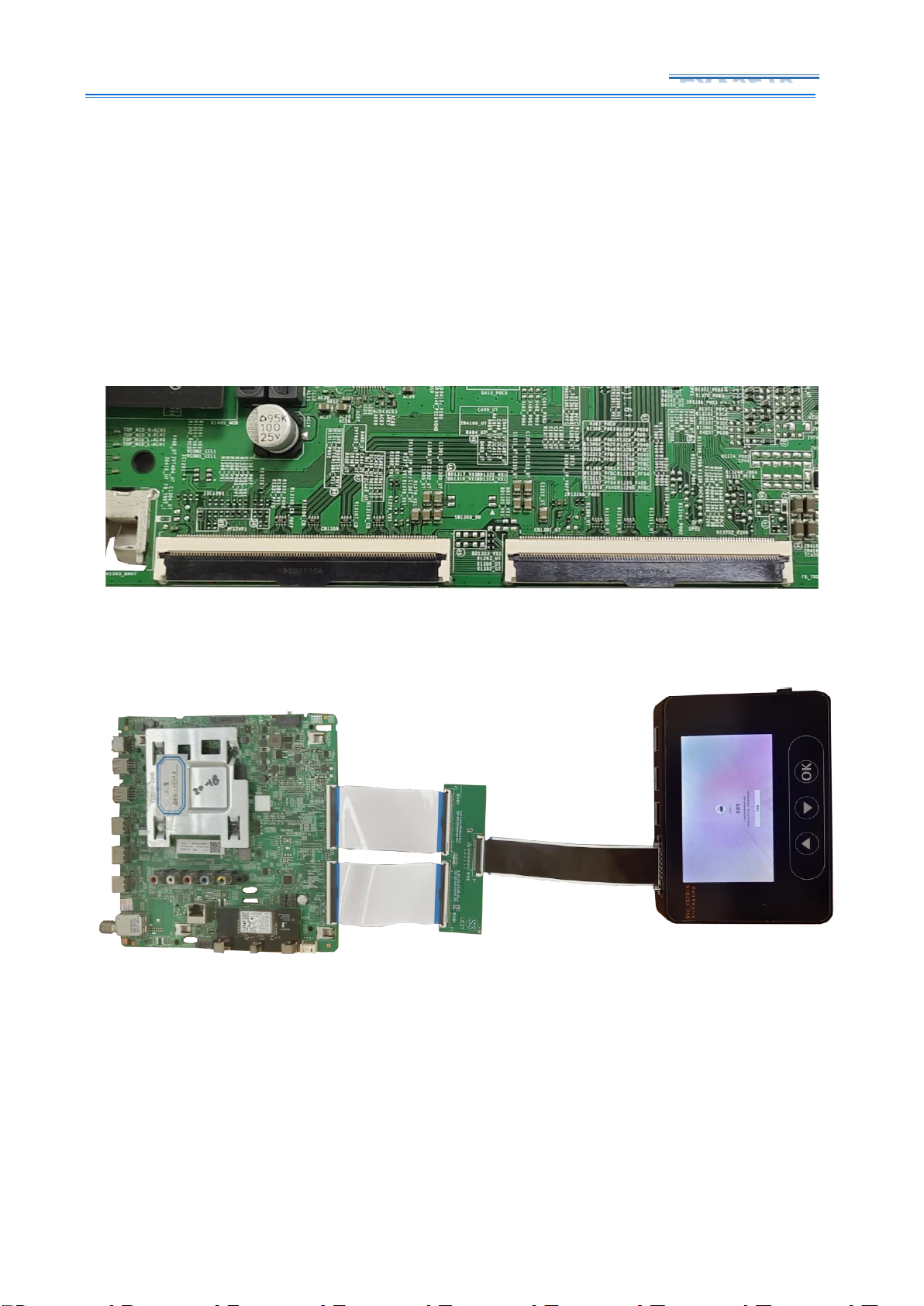
The Samsung USIT signal in P2P signal can be divided into 96Pin single LCD module cable
sequence and 96Pin dual LCD module cable sequence. the USIT single LCD module cable
sequence contains 12 pairs of differential signal cable. Each pair of differential signal cables are
separated by ground wire as shown in Figure 4-7-1, P44-P78 are differential signal cables,
differential cables are separated by ground wire, this cable sequence is tested by converter
board CD/S1, as shown in Figure 4-7-2
Figure 4-7-1 single cable USIT
Figure 4-7-2 single cable USIT S1 connection
Page 15
14 / 27
EXV9210
4.8. Converter board S3 (for Samsung USIT 96Pin dual LCD module cable
sequence)
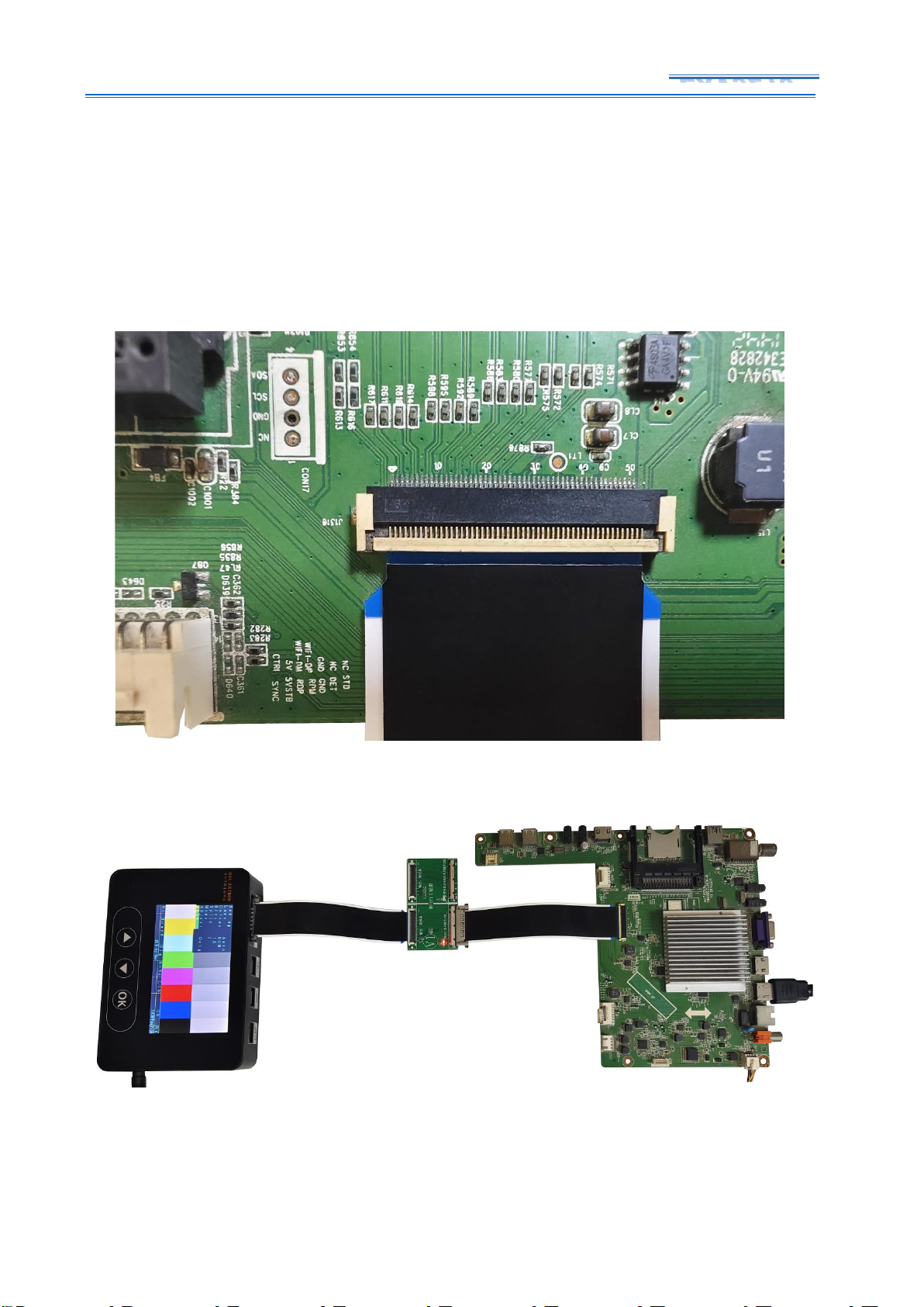
USIT 96Pin dual LCD module cable sequence usually include 12 pairs or 16 pairs of
differential signal cables, each pair of differential signal cables are separated by four pins and
two ground wires. As shown in Figure 4-8-1, the cable sequence contains 12 pairs of differential
signal cables, the left LCD module cable P47-P78 and the right LCD module cable P26-P57 are
all differential signal cable position, each pair of differential signal cable are separated by four
pins and two ground wires. It is tested by S3 converter board, as shown in Figure 4-8-2.
Figure 4-8-1 dual cables USIT
Figure 4-8-2 dual cables USIT S3 connection
Page 16
15 / 27
EXV9210
4.9. Converter board V1 (for 4K-VBYONE cable sequence)
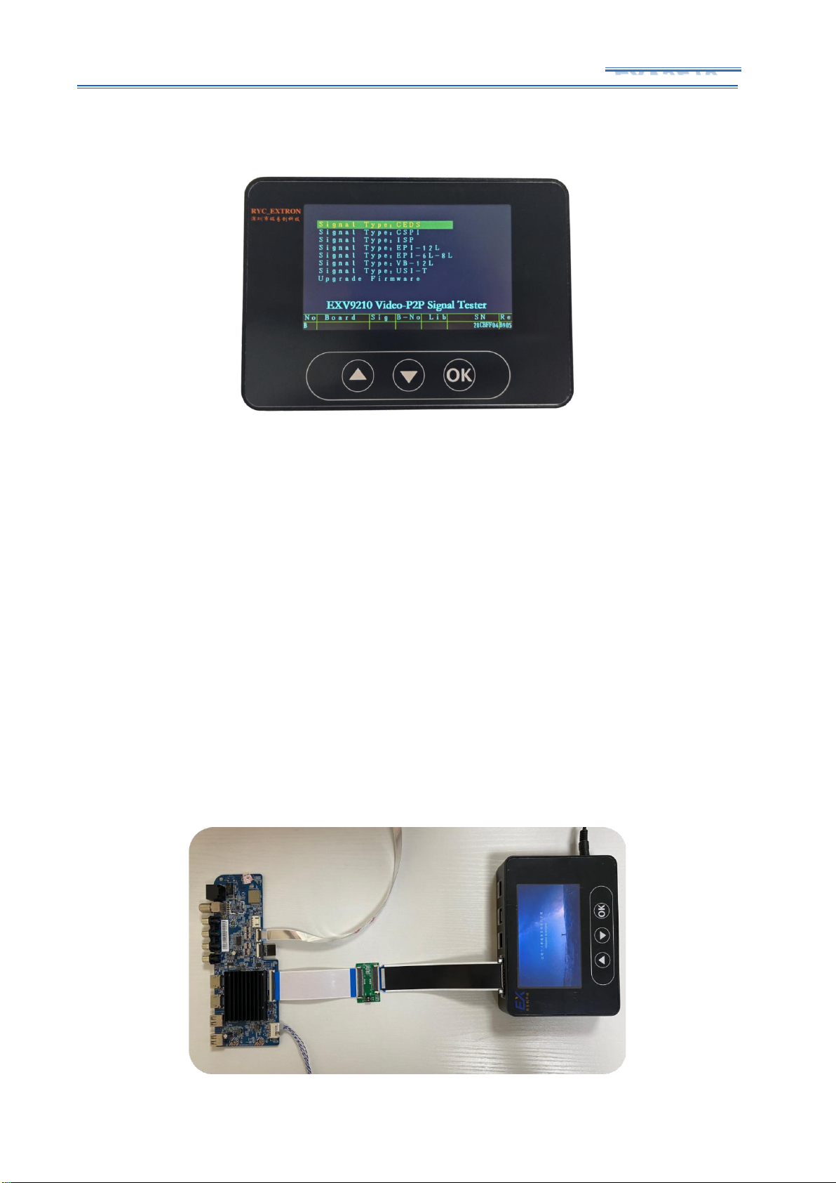
EXV9210 can test P2P signals TV motherboard as well as well as 4K-VBYONE signal
motherboard. 4K-VBYONE cable sequence generally include 8 pairs of differential signal cable,
and separated by the capacitor and the main chip , its VLCD power supply pins are generally 7
or 8. As shown in Figure 4-9-1 for 4K-VBYONE cable sequence, tested by Converter board V1,
as shown in Figure 4-9-2.
Figure 4-9-1 VBYONE signal
Figure 4-9-2 VBYONE signal V1 connection
Page 17
16 / 27
EXV9210
5. User Guide
5.1. Main Interface Description
Figure 5-1 Main interfaces of EXV9210
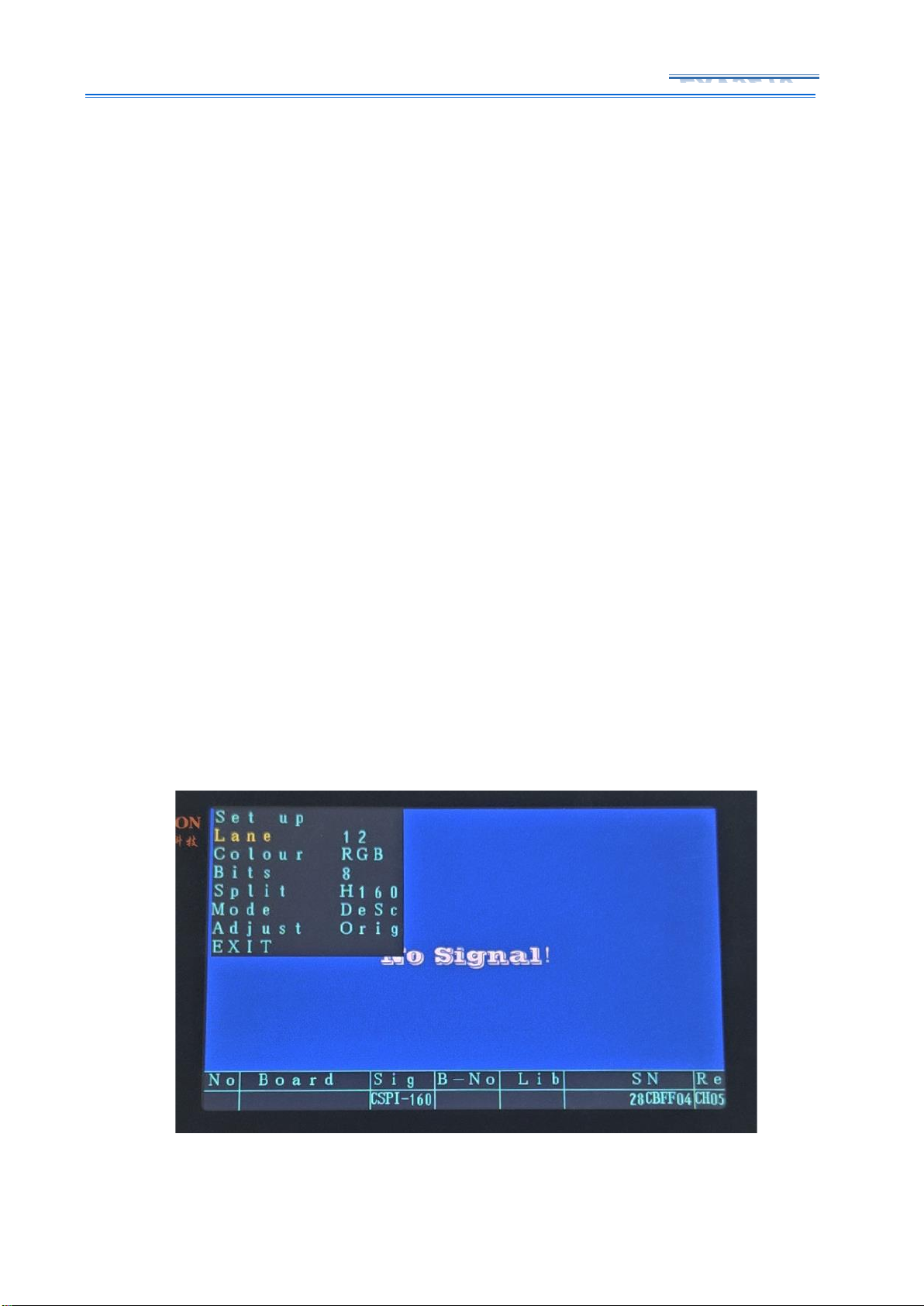
EXV9210 use 5V power and plug in ,you can see main interface as Figure 5-1 shown.In the
main interface, you can use ‘up’ and ‘down’ buttons to select the type of mainboard signals tested,
and press the ‘OK’ button to confirm the selection. After selecting the signal type, you can press
and hold the ‘OK’ button again to return to the initial interface, or power on again.
5.2. Connection Instruction
The P2P motherboard LCD module cable include either 2 60Pin or 1 60Pin FFC LCD module
cable, which cannot be directly connected to the EXV9210 signal converter. It must first pass
through the P2P signal converter board and perform cable sequence conversion before
connecting to the converter for testing. EXV9210 is equipped with 6 converter boards, here
takes a single 60Pin LCD module cable as an example, the connection sample is shown in Figure
5-2, the main board is connected to converter board through a 60Pin LCD module cable,
converted into the 51-pin cable sequence, and then connected to the EXV9210 signal converter.
Figure 5-2 P2P Signal mainboard Connection Map
Page 18
17 / 27
EXV9210
5.3. Testing and Operation
Since there are many types of P2P signals at present, and various types of signals contain
multiple formats, even if the right motherboard type is selected, problems such as
incompleteness and color cast may still occur. It needs to be adjusted to a normal image
through various parameter selections. It should be noted that if the main board signal type is
not selected correctly, the image will not appear, and the "No Signal" screen will be displayed.
Before testing, it is necessary to judge the main board output signal type.
5.3.1. Enter and exit the menu interface
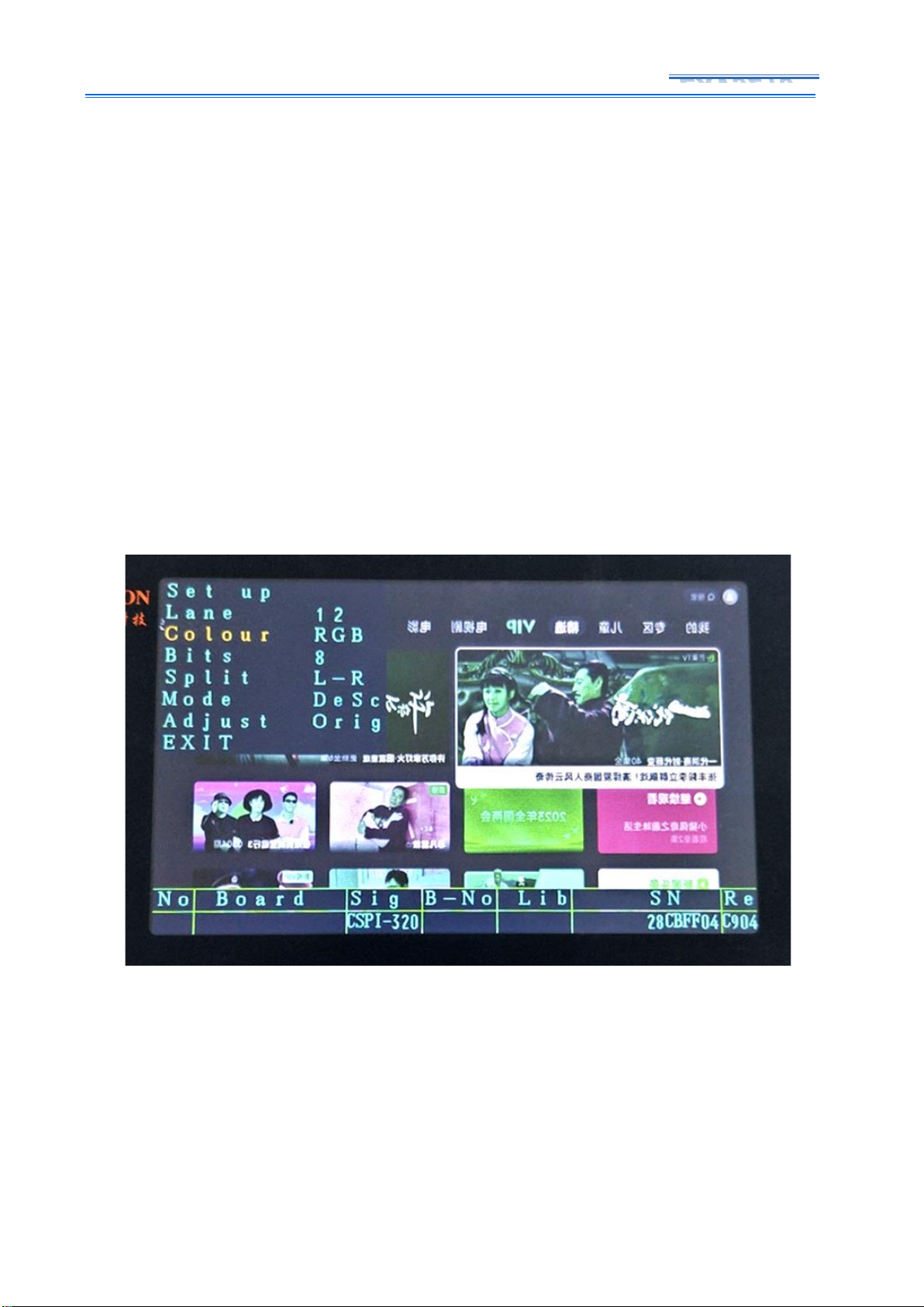
After selecting the mainboard type, touch the “OK” button to call up the screen parameter
setting menu. If the mainboard is not powered on, you can see the screen as shown in Figure 53-1. It should be noted that the menu is only displayed on the 5-inch screen. If an external
monitor is connected via HDMI, the menu will not be displayed on the monitor. After calling out
the screen parameter setting menu, you can select the parameters by pressing the "Up",
"Down" and "OK" buttons. After the setting is completed, you can select "Exit Menu" to exit.
Since the display parameters of different signal motherboards are different, in order to simplify
the setting menu, simplify the operation steps, and select motherboards with different signal
types, the interface of the screen parameter setting menu is different. After the mainboard is
turned on and the image signal is connected, the screen parameters can also be set. If there is
no display or the screen is stuck after connecting to the mainboard signal, it means that the
signal type is wrong, and you can return to the main interface to select the signal type again.
Figure 5-3-1 Menu Display
Page 19
18 / 27
EXV9210
5.3.2. Number of signal lanes
Select the number of signal lanes, you may see, it has options: "6", "8", "12","16", "24".
Except for USIT, the number of signal lanes of various P2P signals is fixed. After the signal type
is selected, the number of signal lanes is also selected by default.
5.3.3. Color Mode
Because if the mainboard signal is connected, the complete image can be displayed on
the EXV9210, but the color of the image is wrong, as shown in Figure 5-3-3, it can be set in the
color mode. Choose motherboards with different signal types, and the color mode menu
options are different. During the test, if you encounter the problem of image color cast, you
can adjust it through the color mode. The above modes are all the modes that have been
tested so far. If other color modes appear in the future, you can upgrade and add color modes
to solve the problem.
Figure 5-3-3 Color Mode Setting
5.3.4. Color bits
There are two settings for color bits: "8" and "10". Currently, the common P2P
signals are all 8 bits, and the USIT motherboard can automatically determine the 8
and 10 bits without the need for manual adjustment. VBYONE has 8-bit and 10-bit
Page 20
19 / 27
EXV9210
options that require manual selection.
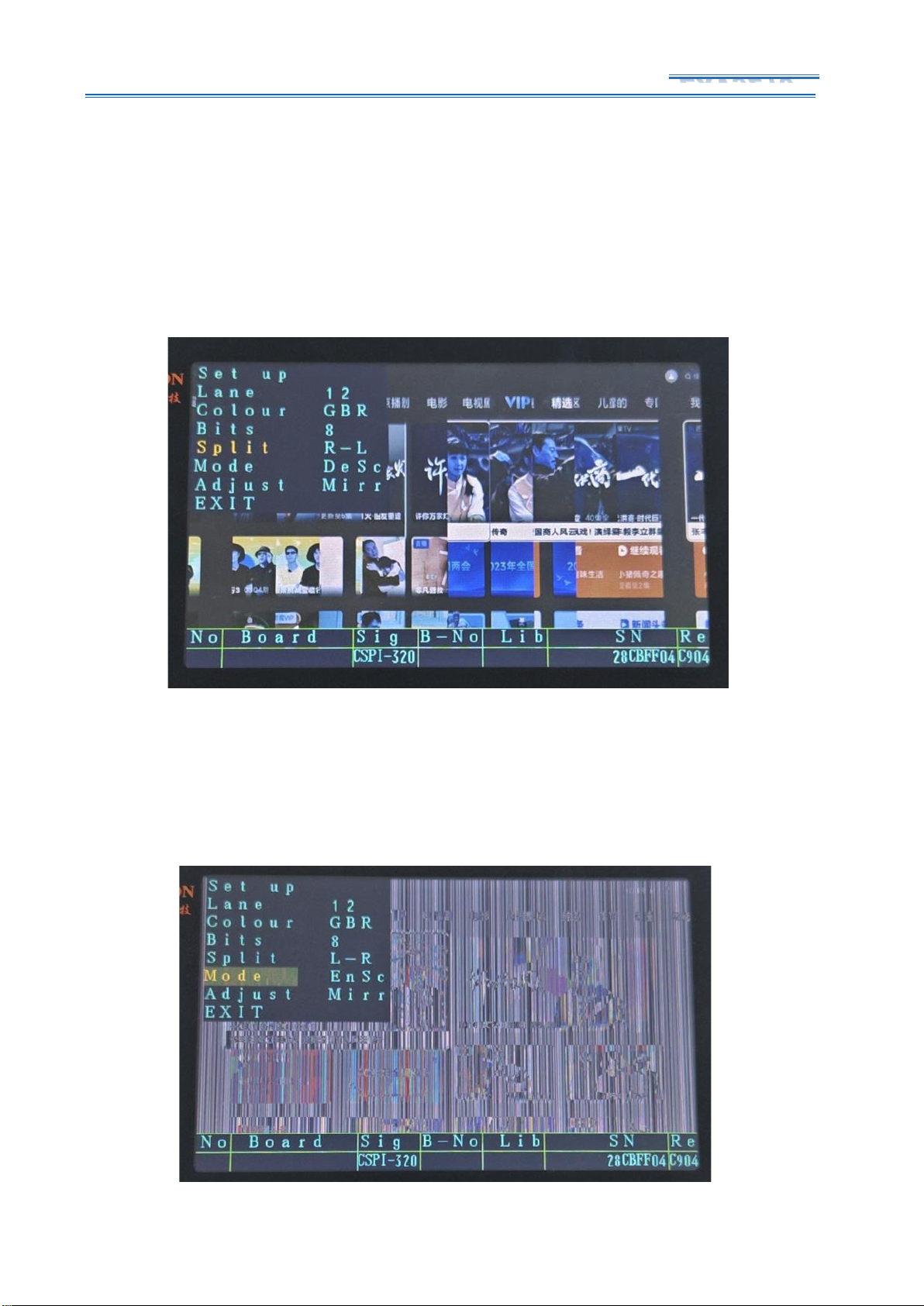
5.3.5. Screen Division
If the mainboard signal is connected, the image will appear multiple screens, which can be
set in “Screen Division”, select different signal motherboards, screen division menu options are
different, some motherboards do not have this options, as shown in Figure 5-3- 5, there are
multiple screens, which can be set and adjusted in screen division menu.
Figure 5-3-5 split screen setting
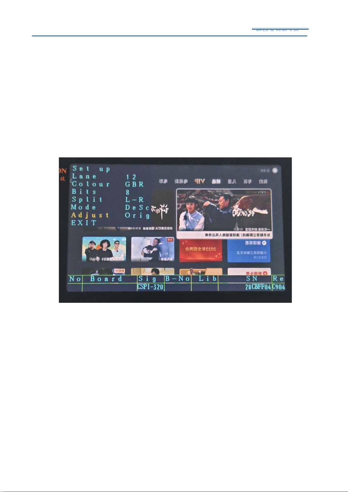
5.3.6. Display Mode
The display mode has two settings: "DeSc" and "EnSc". If the mainboard signal is
connected, EXV9210 cannot see the image clearly, only vertical bars can be seen, as shown in
Figure 5-3-6, you can perform two operations in the display mode. switching of display modes
Figure 5-3-6 Display Mode Setting
Page 21
20 / 27
EXV9210
When entering the testing of CEDS or USIT, there will be another display mode
corresponding to it. Incorrect display mode settings may result in no images. In this case, you
can first check the attached table or consult technical support.
5.3.7. Image Adjustment
As most P2P signal motherboards, the output image is a mirror image, so EXV9210 adds an
image adjustment mode, which can flip the image mirror image. As shown in Figure 5-3-7, the
display mode has two settings: "original" and "mirror". "Original" is the image output by the
mainboard. Selecting the "mirror" mode can mirror the image output from the mainboard.
Figure 5-3-7 Image Adjustment Setting
6. Precious points
➢ Some motherboards may need to adjust multiple parameters, and normal images
cannot appear after adjusting a single parameter.
➢ Please pay attention to regular replacement for consumable flat cable.
➢ The Flat cable interface socket of some motherboards is wider than the screen cable,
and the flat cable can be moved left and right when inserted. Note that the flat cable is
inserted in the middle to prevent misalignment. You can test it with a multimeter before
powering on.
Page 22
21 / 27
EXV9210
➢ Please use the 12V power supply that comes with the machine for the power supply of
the converter. If you want to substitute it, please use the power supply whose AC end is a
three-wire plug to reduce electrostatic interference.
➢ If the image flickers or blick, check LCD module flat cable connection and then power on
again.
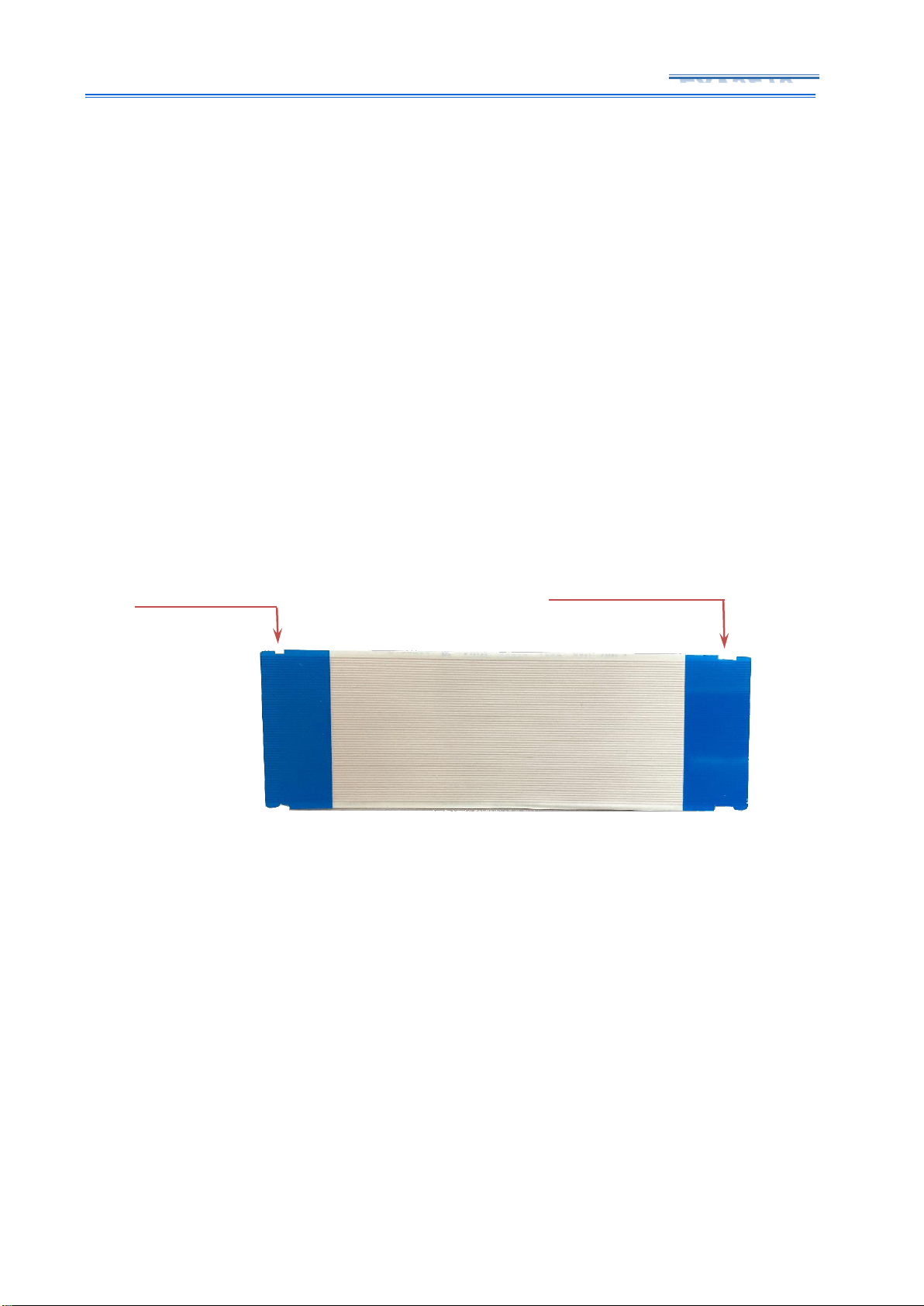
➢ The widths of the gaps at the two ends of flat cable provided by EXV9210 are different.
Pay attention to the direction when connecting. The narrow gap end is connected to
converter board, and the wide gap end is connected to the motherboard. Due to some
motherboards, the interface socket will be deeper, and the commonly used flat cables will
not be long enough. Therefore, it is necessary to connect the wide-notch flat cable, as
shown in Figure 6-1.
Figure 6-1 60Pin Flat cable
Wide notch to connect
Main-boards
Narrow notch to connect
converter boards
Page 23
22 / 27
EXV9210
7. Appendix One
According to the current motherboard test results, types of P2P signal motherboards are
CSPI, CEDS, EPI and iSP. These LCD modules corresponding to these four types of P2P come
from different brands of LCD module manufacturers. During testing, you can help to judge P2P
signal type according to LCD module manufacturer. As shown in Figure 7-1, the corresponding
signals of the P2P signal LCD module produced by several major LCD module manufacturers are
listed. You should be noted that this method is only used as an auxiliary judgment, as a
reference, and cannot ensure 100% accuracy.
Manufacturer
Mainboard Signal type
USIT
Samsung
CSOT
CSPI
BOE
CEDS
LG
EPI
AUO
ISP
Figure 7-1 LCD module and P2P signal types
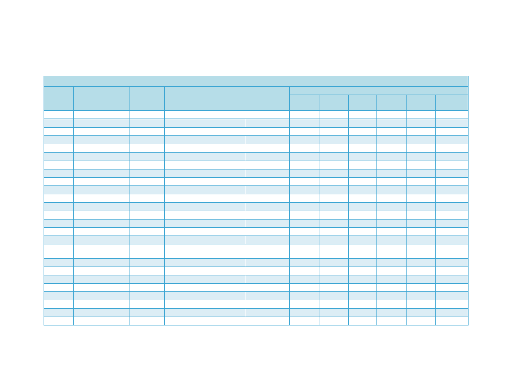
8. Appendix Two, testing table for USI-T main board
NO
主板编号
Pin
转接板
Signal
Lane
Colour
Bits
VSF
Mode
Adjust
1
BN41-02855A
96*1
CD
USIT
12
RGB
8
100Hz
F0
Mirr 2 BN41-02749A-000
96*1
CD
USIT
12
RGB
8
100Hz
F0
Mirr 3 BN41-02703A
96*2
S3
USIT
12
GBR
8
50Hz
F0
Mirr
4
BN41-02568B
96*2
S3
USIT
16
RGB
8
50Hz
F0
Mirr
96*2
S3
USIT
12
GBR
8
50Hz
F1
Mirr 5 BN41-02528A
96*2
S3
USIT
12
GBR
8
50Hz
F2
Mirr 7 BN41-02570B
96*2
S3
USIT
24
RGB/GBR
10
120Hz
F1
Mirr 8 BN41-02504A
96*2
S3
USIT
24
GBR
10
120Hz
F0
Mirr 9 BN41-02710A
96*2
S3
USIT
12
GBR
8
50Hz
F1
Mirr
10
BN41-02634B
96*2
S3
USIT
24
RGB
10
120Hz
F1
Mirr
11
ML41A050594A
96*1
CD
USIT
12
8
60Hz
F3
Mirr
12
BN41-02756B
96*1
CD
USIT
12
GBR
8
50Hz
F0
Mirr
13
BN41-02572A
96*2
S3
USIT
24
GBR
10
120Hz
F3
Mirr
14
BN41-02695A
96*2
S3
USIT
24
GBR
8
120hz
F2
Mirr
Page 24
23 /
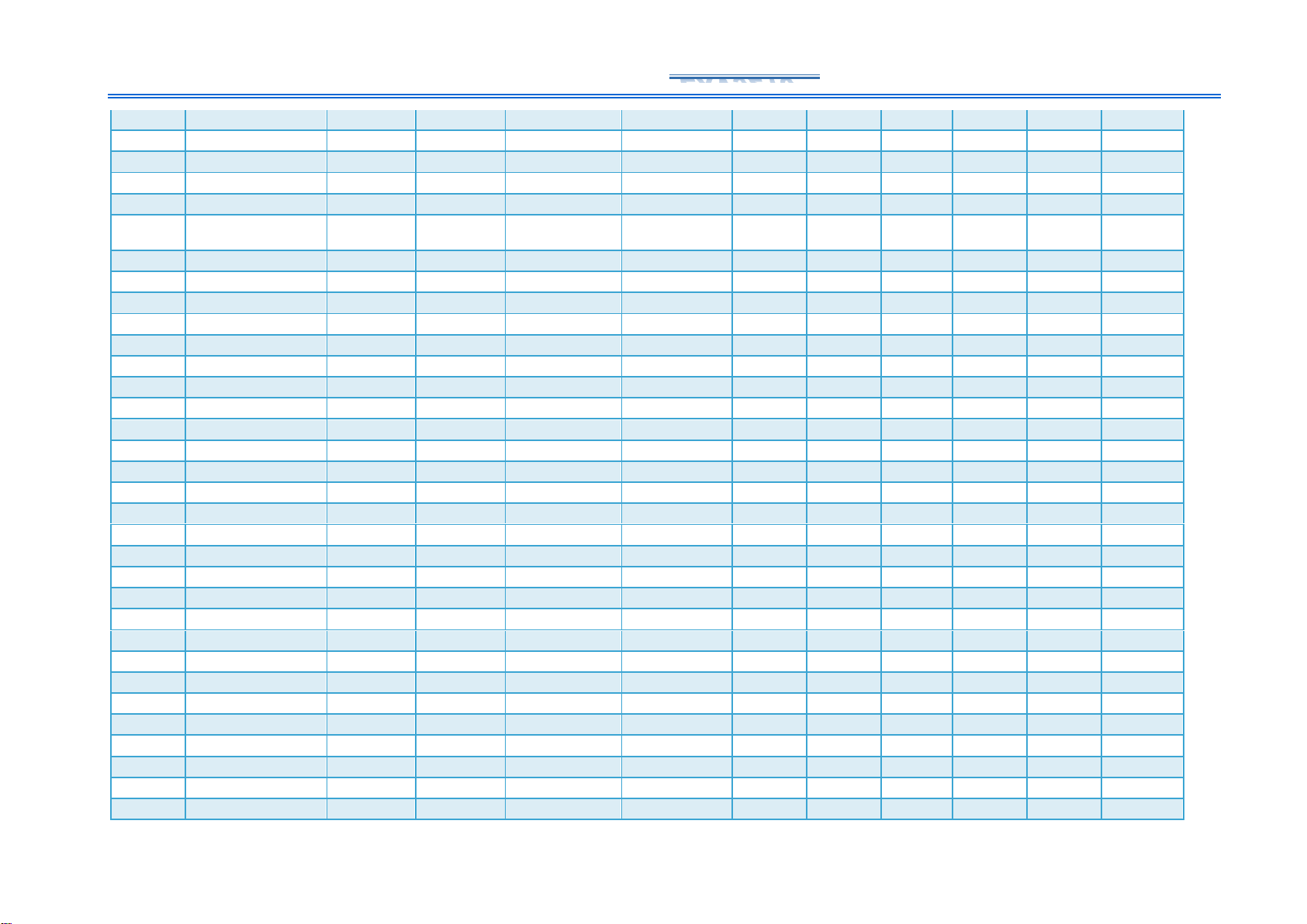
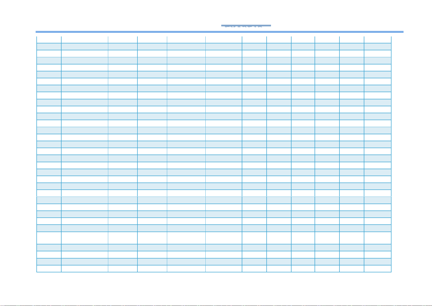
9. Appendix Three testing table for some P2P main board
P2P main-board statistics table (incomplete statistics)
Item
Main-board No.s
Main-board
Brand
LCD
module
cable P
Converter No.s
Signal type
Panel parameter settings
Signal
Channels
Color
Mode
Color bit
Screen
Division
Display
Mode
Image
Adjustment
1
40-M96526-MAB2HG
TCL
dual 60P
C6
CSPI
12
RGB 8 R-L
DeSc
Orig
2
TD.T963T.775(T)
TCL
dual 60P
C6
CSPI
12
RGB 8 L-R
DeSc
Mirr
3
40-T972AH-MPC2HG
TCL
dual 60P
C6
CSPI
12
RGB 8 L-R
DeSc
Mirr
4
40-M848CY-MAC2HG
TCL
dual 60P
C6
CSPI
12
RGB 8 L-R
DeSc
Mirr
5
40-M84806-MAA2HG
TCL
single 60P
C1
CSPI
12
RGB 8 R-L
DeSc
Orig
6
40-T972B1-MPA2HG
TCL
dual 60P
C4
iSP
12
RGB 8 L-R
DeSc
Mirr
7
40-M9652F-MAB2HG
TCL
single 60P
C1
CSPI
12
GBR 8 L-R
DeSc
Mirr
8
40-T963A4-MAB2HG
TCL
single 60P
C1
CSPI
12
RGB 8 L-R
EnSc2
Mirr
9
TT963B2
TCL
dual 60P
C6
CSPI
12
Comb
8
R-L
DeSc
Orig
10
TT963B1
TCL
dual 60P
C6
CSPI
12
RGB
8
H160
DeSc
Mirr
11
40-M848C6-MAD2HG
TCL
dual 60P
C6
CSPI
12
RGB 8 R-L
DeSc
Orig
12
TD.RT2851MT.776(T)
TCL
dual 60P
C6
CSPI
12
GBR
8
H160
DeSc
Mirr
13
TPD.T972T.PC775
TCL
dual 60P
C6
CSPI
12
RGB 8 R-L
DeSc
Orig
14
201-MT963B1N-02
TCL
dual 60P
C6
CSPI
12
RGB
8
H160
DeSc
Mirr
15
40-T972A5-MAD2HG
TCL
dual 60P
C6
CSPI
12
GBR 8 L-R
DeSc
Mirr
16
40-T982L2-MAC2HG
TCL
dual 60P
C6
CSPI
12
RGB 8 L-R
DeSc
Mirr
17
1.30.01.TTL972D100-04
TCL
dual 60P
C6
CSPI
12
RGB 8 R-L
EnSc
Orig
18
40-T972AQ-MPA2HG
TCL
dual 60P
C6
CSPI
12
RGB 8 R-L
EnSc
Orig
19
40-T972AM-MPA2HG
TCL
dual 60P
C6
CSPI
12
RGB 8 R-L
DeSc
Orig
20
40-T972A7-MAB2HG
TCL
dual 60P
C6
CSPI
12
GBR 8 L-R
DeSc
Orig
21
40-M848CD-MAA2HG
TCL
dual 60P
C5
iSP
12
RGB 8 L-R
EnSc
Mirr
22
TPD.T972T.PC779
TCL
dual 60P
C6
CSPI
12
RGB 8 R-L
EnSc
Orig
23
40-M9652F-MAC2HG
TCL
single 60P
C1
CSPI
12
GBR 8 L-R
DeSc
Mirr
24
40-T982L4-MAC2HG
TCL
dual 60P
C6
CSPI
12
RGB 8 L-R
DeSc
Mirr
25
TPD.T972T.PC778
TCL
dual 60P
C6
CSPI
12
RGB 8 R-L
DeSc
Orig
Page 25
24 / 27
EXV9210
26
40-M848CJ-MAA2HG
TCL
dual 60P
C6
CSPI
12
Comb
8
R-L
DeSc
Orig
27
40-T9722A4-MPB2HG
TCL
dual 60P
C6
CSPI
12
RGB 8 L-R
DeSc
Mirr
28
40-T972A7-MPC2HG
TCL
dual 60P
C6
CSPI
12
Comb
8
R-L
DeSc
Orig
29
40-M9652A-MAB2HG
TCL
dual 60P
C6
CSPI
12
Comb
8
R-L
DeSc
Orig
30
40-T972AH-MPE2HG
TCL
dual 60P
C6
CSPI
12
Comb
8
R-L
EnSc
Orig
31
40-M838CMMAC2HG
TCL
dual 60P
C6
CSPI
12
RGB 8 L-R
DeSc
Mirr
32
40-MR17T5-MAA2HG
TCL
dual 60P
C6
VB12
12
8
R-L
Orig
33
40-M653G2-MAC2HG
TCL
single 96P
CC
CSPI
12
RGB
8
120Hz
EnSc
Mirr
34
40-M653J1-MAA2HG
TCL
single 96P
CC
CSPI
12
RGB
8
120Hz
EnSc
Mirr
35
40-T963T4-MAB2HG
TCL
dual 60P
C4 改
EPI-6L-8L
6
RGB1
8
Nor1
DeSc
Mirr
36
40-R51MPD-MAC2HG
TCL
dual 60P
C6
CSPI
12
RGB 8 R-L
EnSc
Orig
37
35024151
Konka
dual 60P
C2
EPI-12L
12
RGBW
8
——
——
Mirr
38
35023559
Konka
dual 60P
C2
EPI-12L
12
RGBW
8
——
——
Mirr
39
35023120
Konka
dual 60P
C2_CR
EPI-12L
12
GBWR
8
——
——
Mirr
40
35023995
Konka
dual 60P
C3
EPI-6L-8L
6
RGB0 8
EnSc
Mirr
41
35023230
Konka
dual 60P
C2_CR
EPI-12L
12
GBWR
8
——
——
Mirr
42
35024926
Konka
dual 60P
C3
EPI-6L-8L
6
RGB0
8
——
——
Mirr
43
35024941
Konka
dual 60P
C4
CEDS
12
GBR 8
Mirr
44
35025002
Konka
dual 60P
C6
CSPI
12
RGB 8 R-L
EnSc 45
35023119
Konka
dual 60P
C2_CR
EPI-12L
12
GBWR
8
——
——
Mirr
46
35023030
Konka
dual 60P
C2
EPI-12L
12
GBWR
8
——
——
Mirr
47
35026166
Konka
dual 60P
C4
CEDS
12
BGR
8
H160
Kon0
Mirr
48
35023199
Konka
dual 60P
C2
EPI-12L
12
RGBW 8
Mirr
49
35023887
Konka
dual 60P
C2
EPI-12L
12
RGBW 8
Mirr
50
35025658
Konka
dual 60P
C4
EPI-12L
12
RGBW 8
Mirr
51
35024406
Konka
dual 60P
C3
EPI-6L-8L
6
EnSc
52
35023899
Konka
dual 60P
C3
EPI-6L-8L
6
EnSc
53
35022752
Konka
dual 60P
C2
EPI-12L
12
GBWR
8
——
——
Mirr
54
35022505
Konka
dual 60P
C2
EPI-12L
12
GBWR
8
——
——
Mirr
55
35023631
Konka
dual 60P
C2_CR
EPI-12L
12
RGBW 8
56
RSAG7.820.7918
Hisense
dual 60P
C5
iSP
12
RGB 8 R-L
EnSc
Mirr
57
RSAG7.820.9850
Hisense
dual 60P
C4
CEDS
12
BGR
8
——
——
Mirr
58
RSAG7.820.8768
Hisense
dual 60P
C5
iSP
12
RGB 8 L-R
EnSc
Mirr
Page 26
25 / 27
EXV9210
59
RSAG7.820.8002
Hisense
dual 60P
C5
iSP
12
RGB 8 R-L
EnSc
Mirr
60
RSAG7.820.10510
Hisense
dual 60P
C4
CEDS
12
BGR
8
——
——
Mirr
61
RSAG7.820.9428
Hisense
dual 60P
C5
iSP
12
RGB 8 L-R
EnSc
Mirr
62
RSAG7.820.8802
Hisense
dual 60P
C4
EPI
12
RGBW
8
——
——
Mirr
63
RSAG7.820.10637
Hisense
single 68P
C7-海信/C4+
CEDS
12
BGR
8
——
——
Mirr
64
RSAG7.820.10688
Hisense
single 68P
C7-海信/C5+
iSP
12
RGB 8 L-R
EnSc
Mirr
65
RSAG7.820.12206
Hisense
single 68P
C7-海信/C6+
CSPI
12
RGB 8 L-R
EnSc
Mirr
66
RSAG.820.10264
Hisense
dual 60P
C4
CEDS
8
GBR
8
H320
DeSc
Mirr
67
RSAG7.820.9132
Hisense
dual 60P
C5
i SP
12
RGB 8 L-R
EnSc
Mirr
68
RSAG7.820.9180
Hisense
dual 60P
C5
iSP
12
RGB 8 L-R
EnSc
Mirr
69
RSAG7.820.10360
Hisense
dual 60P
C5
iSP
12
GBR 8 L-R
EnSc
Mirr
70
RSAG7.820.9603
Hisense
dual 60P
C6
CSPI
12
Comb
8
R-L
EnSc
Mirr
71
RSAG7.820.9250
Hisense
dual 60P
C4
CEDS
12
RGB
8
H160
Mirr
72
RSAG7.820.12085
Hisense
single 68P
C7-海信
CEDS
12
BGR
8
H320
Mi0
Mirr
73
RSAG7.820.9479
Hisense
dual 60P
C5
iSP
12
RGB 8 L-R
EnSc
Mirr
74
RSAG7.820.8803
Hisense
dual 68P
C2
CEDS
12
BGR
8
H320
Nor0
Mirr
75
RSAG7.820.9638
Hisense
dual 68P
C2
CEDS
12
BGR
8
H320
Mi0
Mirr
76
RSAG7.820.9538
Hisense
dual 68P
C2
CEDS
12
BGR
8
H320
Mi0
Mirr
77
RSAG7.820.10527
Hisense
dual 60P
C4
CEDS
12
BGR
8
H320
Mi0
Mirr
78
RSAG7.820.12440
Hisense
single 68P
C7-海信
CEDS
12
RGB
8
H320
Mi0
Mirr
79
RSAG7.820.9516
Hisense
dual 60P
C6
CSPI
12
GBR 8 L-R
EnSc2
Mirr
80
RSAG7.820.13197
Hisense
single 68P
C7-海信
CSPI
12
RGB 8 L-R
DeSc
Mirr
81
5800-A7S770-1P20
Skyworth
single 68P
C8
VB-12
自动
RGB
10
1 分屏
——
Orig
82
5800-A9S200-0P00
Skyworth
dual 60P
C2
EPI
12
GBWR 8
Mirr
83
5800-A9R520-0P00
Skyworth
dual 60P
C2-CR
EPI
12
GBWR 8
Mirr
84
5800-A8H520-1P00
Skyworth
dual 60P
C2
EPI-12L
12
RGBW
8
——
——
Mirr
85
5823-A8S380-0P00
Skyworth
dual 60P
C3
EPI-6L-8L
6
RGBW 8
Nor0
Mirr
86
5800-A8S790-0P60
Skyworth
dual 60P
C2
EPI
12
GBWR 8
Mirr
87
5800-A7S780-0P00
Skyworth
single 68
针
C8
CEDS
12
BGR
8
H320
Mi0
Mirr
88
5800-A9R490-0P10
Skyworth
dual 60P
C2-CR
EPI
12
GBWR 8
Mirr
89
5800-A8H200-0P20
Skyworth
dual 60P
C2
iSP
12
90
A7T855
Skyworth
single 68P
C8
CEDS
12
BGR
8
H320
Nor0
Mirr
91
A7T855
Skyworth
single 68P
C8
VB-12
8
10 2
Page 27
26 / 27
EXV9210
92
A9K56G0
Skyworth
single 68P
C8
CEDS
12
BGR
8
H320
Mi0
Mirr
93
A9K56G0
Skyworth
single 68P
C8
VB-12
8
10 1
Orig
94
5851-A8R391-2P00
Skyworth
dual 60P
C6
CSPI
12
RGB 8 R-L
DeSc
Orig
95
5800-A7S720-0P20
Skyworth
dual 68P
C2
CEDS
12
BGR
8
H320
Mi0
Mirr
96
JUC7.820.10003598
Changhong
dual 60P
C6
CSPI
12
RGB 8 R-L
DeSc
Orig
97
JUC7.820.10004874
Changhong
dual 60P
C4
iSP
12
RGB 8 L-R
DeSc
Mirr
98
JUC7.820.10000030
Changhong
single 60P
C1
CSPI
12
GBR 8 L-R
DeSc
Mirr
99
JUC7.820.00243711
Changhong
dual 60P
C5
iSP
12
RGB 8 L-R
EnSc
Mirr
100
JUC7.820.10002717
Changhong
dual 60P
C6
CSPI
12
GBR 8 R-L
EnSc
Orig
101
JUC7.820.00238776
Changhong
dual 60P
C6
CSPI
12
RGB 8 R-L
DeSc
Orig
102
JUC7.820.10002718
Changhong
single 60P
C1
12
Mirr
103
JUC7.820.00235160
Changhong
dual 60P
C5
iSP
12
GBR 8 L-R
EnSc
Mirr
104
JUC7.820.00236783
Changhong
dual 60P
C3
EPI-6L-8L
6
RGBW
8
——
EnSc
Mirr
105
TD.T963.793
Mi
single 60P
C1
CSPI
12
Comb
8
L-R
DeSc
Mirr
106
DKTV-B014-T963
Mi
single 60P
C1
CSPI
12
GBR 8 R-L
EnSc
Orig
107
TD.MT9632.793
Mi
single 60P
C1
CPSI/CEDS/VBY1
108
DKTV-B015-9638
Mi
single 60P
C1
CPSI/CEDS/VBY1
109
TD.MT9638.791
Mi
single 60P
C1
CPSI/VBY1
110
TD.MT9632.793-RZ4J
Mi
single 60P
C1
CEDS
12
BGR
8
H320
KON0
Mirr
111
TD.MT9638.792
Mi
single 60P
C1
CPSI/VBY1
Note: 1. The P2P main-board, at the output end of the screen line, has a high-voltage GAMA signal output. If connection is wrong, the protection
circuit of the instrument will be damaged, and the internal chip will be seriously damaged. Therefore, it is highly recommended that you should
read the user guide carefully before operation, and make sure you understand the contents, and then operate in strict accordance with the
instructions
2.Some P2P main-boards are plugged into different Panel IDs or flashed with different firmware, and the motherboards can output images of
different signal types to match different panel.
 Loading...