

Page 1
™
Supported Model
• C4-DIN-8REL-E 8-Channel Relay
8-Channel
Relay
Installation Guide
Environmental
Operational Temperature 32˚ F - 104˚ F
(0˚ C - 40˚ C)
Humidity 5% - 95%
Non-condensing
Storage -4˚ F - 158˚ F
(-20˚ C - 70˚ C)
Dimensions
H x W x D 8.5” x 4.3” x 2.3” (215 mm x 109 mm x 57 mm)
DIN Module Width 12M
Weight 2.9 lbs. (1.3 kg)
Shipping Weight 3.3 lbs. (1.49 kg)
Introduction
The Control4® 8-Channel Relay controls up to eight (8) devices from one (1)
module in the Control4 system. It installs in a panelized backbox using typical
wiring standards and communicates to the Control4 system using a CAT5 Ethernet
connection.
Box Contents
• 8-Channel Relay
• Warranty Card
• 8-ChannelRelayInstallationGuide (this document)
• 8-ChannelRelayWiringGuide
Specifications and Supported Fixtures
The specifications are described below.
Model Number C4-DIN-8REL-E
Power Requirements 100-277VAC, 50/60 Hz
Line Feeds (Circuits) 4
Power Consumption 3W
Supported Load Types Incandescent, Halogen, Electronic Low Voltage
Transformers (ELV); Magnetic Low Voltage
Transformers (MLV); Fluorescents; Compact
Fluorescents; LEDs; Motors.
Control Communcations Ethernet
Load Ratings
120V 240V 277V
Module Max 64A 64A 64A
Line-In 1 Max 16A 16A 16A
Line-In 2 Max 16A 16A 16A
Line-In 3 Max 16A 16A 16A
Line-In 4 Max 16A 16A 16A
Individual Channel Max 16A
1HP
Connectors
Sixteen (16) Line Voltage
Screw Terminals (Line 1, Line
2, Line 3, Line 4, Neutral,
Earth Ground, Loads 1-8, Aux
In, Aux Out, unused)
One (1) Ethernet RJ-45
One (1) 26AWG to 12AWG (.12mm2 to 4mm2)
per terminal
16A
2HP
16A
Warnings and Considerations
WARNING! This device must be installed by a licensed electrician in
accordance with all national and local electrical codes..
WARNING! Improper use or installation can cause SERIOUS INJURY,
DEATH or LOSS/DAMAGE OF PROPERTY.
WARNING! This device must be protected by a circuit breaker (20A max).
WARNING! Ensure that all circuit breakers feeding into the panel are OFF
before installing or servicing the devices.
CAUTION! The panel used with this device is air cooled. Install the panel
in a location where the vented cover is not blocked. At least 12 inches
(30cm) clearance is required away from the front of the panel. Some local
codes may require as much as 30 inches clearance.
CAUTION! Only install this device indoors.
IMPORTANT! Using this product in a manner other than outlined in this
document voids your warranty. Further, Control4 is NOT liable for any
damage incurred with the misuse of this product. See “Troubleshooting.”
IMPORTANT! Changes or modifications not expressly approved by
Control4 could void the user’s authority to operate the equipment.
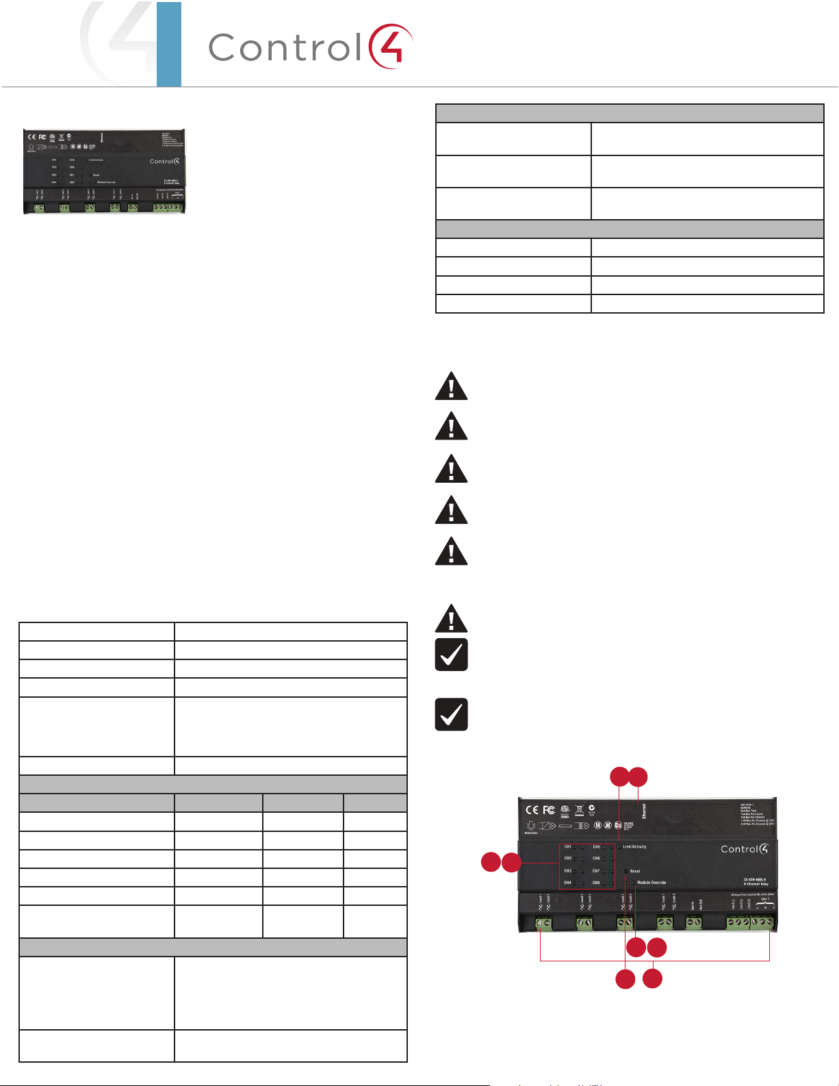
Figure 1. Front View
2
6
3
4
7
8
1
5
1 Line Voltage Terminals
2 Link/Activity LED
3 Channel Status LEDs
4 Channel Buttons
Page 2
5 Reset Button (recessed)
6 Ethernet RJ-45 Port
7 Module Status LED
8 Module Override Button
Pre-Installation Instructions
Before You Install in a Control4 Panel
1 Use Composer Pro to add the 8-Channel Relay to a project, define its location
in a panel, and print the Panel, Module, or Load Schedule Reports. See the
ComposerProUserGuide for details.
2 Install the panel following the instructions in the 5-Slotand2-SlotPanel
InstallationGuide.
3 Install and wire the Terminal Block for the 8-Channel Relay following the
instructions in the TerminalBlockInstallationGuide and in the location
defined by the Composer Pro Panel Reports.
4 Verify that all bypass jumpers are securely installed in the Terminal Block
assemblies. Each 8-Channel Relay Terminal Block assembly should have eight
(8) bypass jumpers installed, connecting each black Terminal Block to two
(2) red Terminal Blocks, and connecting each set of three (3) white Terminal
Bocks together.
Figure 2. Terminal Block Bypass Jumpers
Install in a Control4 Panel
1 The 8-Channel Relay should be installed in the panel next to the previously-
installed 8-Channel Relay Terminal Block. The location of the device in the
panel is defined by the Composer Pro Panel Report.
2 With the green screw terminals on the left side of the 8-Channel Relay, hold
the Relay upright and angle it to the right so that the right side of the module
fits onto the rail in the panel.
NOTE: The 8-Channel Relay installs with the Line Voltage Connector on
the left side and the Ethernet port on the right side.
3 With the right side already in place, push forward on the left side of the
8-Channel Relay to snap it onto the rail (see Figure 3).
Figure 3. Snap on the 8-Channel Relay - Control4 Panels
Bypass
Jumpers
5 Turn on the circuit breaker(s) feeding the Terminal Block. Verify that
the circuit breaker(s) do not trip. If a breaker trips, do not proceed with
installation until the problem has been resolved.
6 Turn OFF the circuit breakers for all lines coming into the panel.
7 Remove the four (4) bypass jumpers that connect each black terminal to two
(2) red terminals by unscrewing all three (3) screws in each bypass jumper
until the entire bypass jumper can be pulled out. (Do NOT remove the bypass
jumpers connecting the white Terminal Blocks together.)
IMPORTANT! Store the bypass jumper for possible later use. The bypass
jumper should be reinstalled any time the load will be serviced. Test the
circuit with the jumper installed prior to removing the jumper again.
Damage to the module caused by miswiring is not covered by the
warranty.
Before You Install in a Third-Party DIN Rail Panel
1 Install the third-party panel according to the third-party instructions.
2 Install the panel in a well-ventilated area.
IMPORTANT! Test all wiring for short circuits before installing the module.
Damage to the module caused by miswiring is not covered by the
Control4 warranty.
Installation Instructions
CAUTION! Turn o all breakers feeding into the panel before proceeding.
NOTE: To remove the module, push the module toward the left side, pull
out from the left side, and remove it from the right side of the rail.
4 Wire the module according to the wiring diagrams in the 8-ChannelRelay
WiringGuide and the reports from Composer Pro.
NOTE: Wiring between the Terminal Blocks and the module will be easiest
when stranded wire is used. All wires between the Terminal Block and
the 8-Channel Relay must use the same gauge wire as the field wiring
connected to the Terminal Block.
• At the terminal block side, strip the wires 0.35 in. (9 mm) and tighten
to 7 in-lb (0.8Nm).
• At the module side, strip the wires 0.3 in. (7 mm) and tighten to 5.3
in-lb (0.6Nm).
5 On the right side of the 8-Channel Relay, connect the Ethernet CAT5 cable to
the RJ-45 port.
6 Install the other modules in the panel as defined in the Panel Reports from
Composer Pro and their respective installation guide.
7 Turn the circuit breakers back ON and test all connected loads by clicking the
channel override buttons.
Install in a Third-Party Panel
CAUTION! Turn o all breakers feeding into the panel before proceeding.
1 With the green screw terminals facing down, hold the 8-Channel Relay
lengthwise and angle it up so that the top side of the module fits onto the rail.
NOTE: The 8-Channel Relay installs with the Line Voltage Connectors
facing down and the Ethernet port facing up.
2 With the top side already in place, rotate the 8-Channel Relay down to snap it
onto the rail (see Figure 4).
Page 3

™
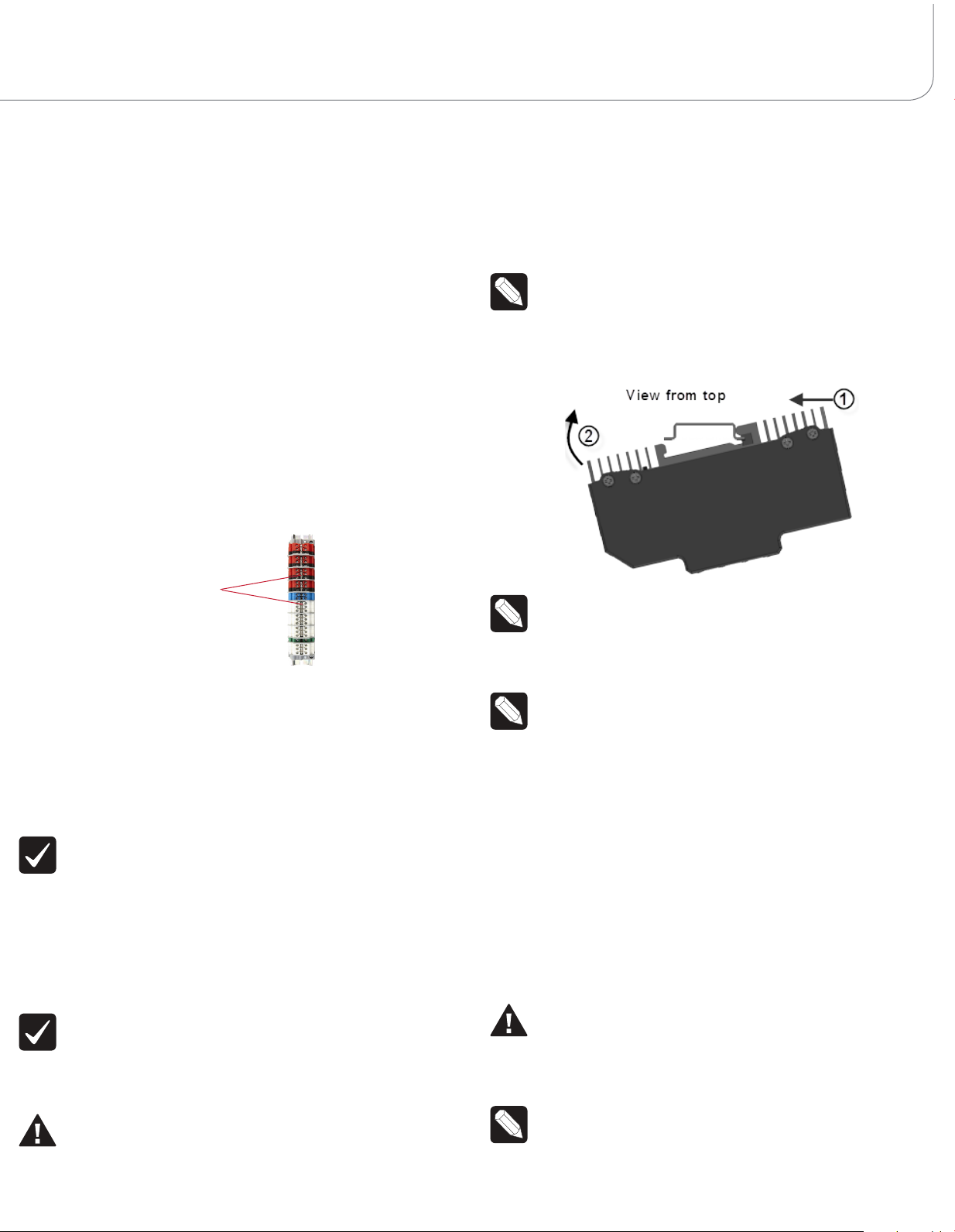
Figure 4. Snap on the 8-Channel Relay - Third-Party Panels
NOTE: To remove the module, pull the module out from the bottom, rotate
the module up, and lift it o.
3 Wire the module according to the wiring diagram in the 8-ChannelRelay
WiringGuide and the reports from Composer Pro.
Strip the wires 0.3 in. (7 mm) and tighten to 5.3 in-lb (0.6Nm).
4 On the top of the 8-Channel Relay, connect the Ethernet CAT5 cable to the
RJ-45 port.
5 Install the other modules in the panel as defined in their respective installation
guide.
6 Turn the circuit breakers back ON and test all connected loads by clicking the
channel override buttons.
Additionally, the browser configuration tool can be used to view the current
temperature of the module as well as any channel short circuit faults.
LEDs
The indicator lights on the front of the 8-Channel Relay communicate the status of
the device.
Indicator LED Color Status Notes
Module Override Blue Power on, normal
Black O
Red Thermal overload See “Faults” section
Channels Blue Load on
Black Load o
Red Short Circuit Fault See “Faults” section
Link/Activity Solid Green Link
Orange Activity
Flashing
Green
operation
below
below
Firmware updating Flashing gets faster
as update proceeds
Channel and Module Override Buttons
During normal operation, the buttons on the front of the 8-Channel Relay
behave in the following manner:
Wiring Diagrams
The wiring diagrams show the wiring details for Control4 8-Channel Relays. Refer
to the 8-ChannelRelayWiringGuideto view those diagrams.
Operation and Configuration
Composer Pro Configuration and Reports
Use Composer Pro to define the properties of each 8-Channel Relay, its location
in a panel, and the loads that are connected to it. Composer Pro can then be used
to generate Panel Reports, Module Reports, and Load Schedule Reports. These
reports are essential to ensuring that each 8-Channel Relay is properly installed
in the correct location and wired to the appropriate loads. Please refer to the
ComposerProUserGuide for detailed information.
Browser Configuration Tool
Basic properties for each load as well as the network configuration for the
8-Channel Relay can be set using a standard web browser.
To open the configuration page, simply start the browser and type in the
IP address of the Relay. Alternatively, the Properties page for the module in
Composer Pro > System Design view has a link to the browser configuration page.
The browser configuration tool can be used to set the following properties:
• Network Settings
- DHCP Enable/Disable
- IP Address
- Subnet Mask
- IP Gateway
• Control Settings for each Channel
- Module Override Level
Button Action Result
CH1-CH8 Click Toggles the load on and
o.
Module Override Click Toggles between the
module override scene
and all channels o.
Hold for five (5) seconds Sets the module override
scene to current channel
on/o settings. The Module Override LED will
blink rapidly to indicate
that the override scene
has been saved.
The following button tap sequences are available using the CH1 and CH8
buttons.
Function CH1 CH8 CH1
Identify 4
Reboot Device 15
Factory Reset 9 4 9
Reset Button
NOTE: The Reset button is recessed and must be pressed using a
paperclip or similar device.
A single click of the Reset button is equivalent to powering the 8-Channel Relay
o and back on. Additionally, certain special activities can be accomplished by
pressing and holding a specific button while clicking the Reset button. Note
that the same activity is possible by pressing and holding the designated button
while power cycling the 8- Channel Relay:
Page 4

Hold Button While
Clicking Reset
CH7 Sets the device to DHCP-disabled and forces the IP
address to 192.168.1.200.
CH8 Toggles between DHCP-enabled and DHCP-disabled.
Module Override Restores the factory image (do not perform unless
directed to do so by Control4 Technical Support).
Result
Overtemp Fault
Symptom Possible Solution
Verify that all line inputs on the module (Line 1, 2, 3, &
4) are all receiving power.
Verify that the light bulb is not burned out.
Loads do not turn o Verify that the Terminal Block jumpers that connect
the black Terminal Block to the red Terminal Blocks
have been removed.
Module overheats Verify that the module is receiving proper ventilation.
• Occurs if the module reaches an unsafe operating temperature.
• All loads attached to the module will turn o.
• The Module Override LED will turn red.
• The fault condition cannot be cleared nor loads turned back on until the
device has reached a safe operating temperature. Once the device has
reached a safe operating temperature, the fault will automatically clear. Note,
though, that loads will not automatically turn back on after the fault has
cleared.
Manual Overrides
Prior to installation of the control system, or in case a problem occurs with the
control system or the network, it is possible to control the loads attached to the
8-Channel Relay via several methods:
• Override Scene
- The module override scene is stored in the module itself and does not
require interaction from the control system.
- The default setting for this override scene is all loads on.
- The override scene settings can be changed using the buttons on the
front of the module (see the “Channel and Module Overrides” section
above), the Browser Configuration Tool, or Composer Pro.
• Module Override Button
- Clicking the Module Override button toggles the attached loads between
the stored override scene and all loads o.
• Auxiliary Override Contacts
- The Aux In and Aux Out terminals on the 8-Channel Relay can be wired
to a standard line-voltage toggle switch installed in a hidden but convenient
location, such as a closet.
- Each time the attached switch is flipped, the 8-Channel Relay will toggle
between the stored override scene and all loads o.
- If desired, a single toggle switch can be wired to the Aux In contact on
multiple Control4 Panelized Lighting modules, but all modules sharing an
auxiliary override switch MUST BE ON THE SAME ELECTRICAL PHASE.
- The desired location of the Auxiliary Override Switch can be defined in
Composer Pro for each module. This information will appear in the Module
Report generated by Composer Pro.
• Channel Override Buttons
- The channel override buttons on the front of the module provide individual
control of each load attached to the 8-Channel Relay. Click the specific
Channel Override button to toggle the load on/o.
Regulatory/Safety Information
To review Regulatory information for your particular Control4 products, see
the information located on the Control4 website at: http://www.control4.com/
regulatory/.
Warranty
For complete warranty information, including details on consumer legal rights as
well as warranty exclusions, review the Warranty card or visit www.control4.com/
warranty.
About this Document
Part Number: 200-00235, Rev A 09/28/2012
Troubleshooting
Symptom Possible Solution
Module does not
power on
Load does not turn on Verify that the load is wired to the proper channel
Copyright ©2012 Control4. All rights reserved. Control4, the Control4 logo, the Control4 iQ logo and the Control4 certified logo are registered trademarks or trademarks of Control4 Corporation in
the United States and/or other countries. All other names and brands may be claimed as the property of their respective owners Pricing and specifications are subject to change without notice
Verify that the circuit breaker is on.
Verify that Line-In 1 is connected to the power.
terminal.
 Loading...