

Page 1
™
Load Symbols
Wireless Puck
Dimmer and
Switch Module
Installation Guide
Supported Models
• C4-DM201-Z Wireless Puck Dimmer
• C4-SM201-Z Wireless Puck Switch
Box Contents
• Wireless Puck Module
• Warranty Card
• WirelessPuckDimmerandSwitchModuleInstallationGuide (this document)
Specifications and Supported Fixtures
Power: 220-240VAC 50/60 Hz
C4-DM201-Z
Dimmer
Supported Load Types: Incandescent; Halogen;
Magnetic Low Voltage
(MLV); Electronic Low
Voltage (ELV); Phase-cut
dimmable: Fluorescent,
Compact Fluorescent,
and LED fixtures.
Maximum Load*
(@240V)
Minimum Load* with
Neutral
(@240V)
Minimum Load* without Neutral
(@240V)
Auxiliary LEDs 220-240VAC
Operating
Temperature:
Communications: IEEE 802.15.4, 2.4 GHz, 15-channel, spread spectrum
* Notes: The maximum and minimum load requirements for fluorescent, CFL and LED loads can
vary greatly depending upon the specific fixture and/or bulb being used. At higher wattages,
these load types have significant in-rush current which can trip the protection circuitry on the
device. At low wattages, some CFL and LED loads will not be able to completely shut o.
In both cases, the quality and performance of these load types varies greatly from manufacturer
to manufacturer. When using these load types, we recommend testing in advance. If problems
are found, simply changing to a dierent bulb manufacturer may solve the problem.
Additionally, we do not recommend the use of fluorescent, CFL, or LED loads without a neutral
connected to the Dimmer due to the capacitive nature of these load types.
Incandescent: 400W
Halogen: 400W
Fluorescent: 250W
CFL: 250W
LED: 250W
Incandescent: 5W
Halogen: 5W
Fluorescent: 10W
CFL: 10W
LED: 10W
Incandescent: 10W
Halogen: 10W
Fluorescent: N/A
CFL: N/A
LED: N/A
All load ratings are based on an ambient temperature
of 25 degrees Celsius.
radio
C4-SM201-Z
Switch
Incandescent; Halogen;
Magnetic Low Voltage
(MLV); Electronic Low
Voltage (ELV); Fluorescent; Compact Fluorescent; LED fixtures; and
Motors (ceiling fan and
exhaust fan).
Incandescent: 400W
Halogen: 400W
Fluorescent: 250W
CFL: 250W
LED: 250W
Motor: 1/4 HP
None
N/A
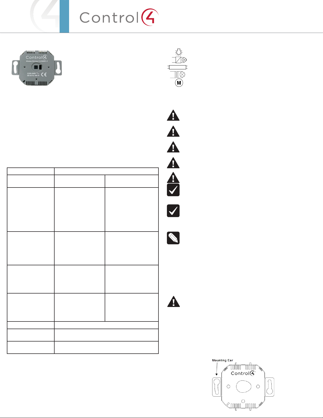
Incandescent Lamp
Electronic Step-Down Converter
Electronic Ballast Fluorescent Lamp
Iron Core Transformer
Motors
Warnings and Considerations
WARNING! Install in accordance with all national and local electrical
codes.
WARNING! Improper use or installation can cause SERIOUS INJURY,
DEATH or LOSS/DAMAGE OF PROPERTY.
WARNING! If you are unsure about any part of these instructions, consult
a qualified electrician.
WARNING! If you are not sure which wires are Live, Load, Neutral, or
Earth/Ground, have a trained electrician perform the installation.
CAUTION! Do not install to control a receptacle.
IMPORTANT! Using this product in a manner other than outlined in this
document voids your warranty. Further, Control4 is NOT liable for any
damage incurred with the misuse of this product.
IMPORTANT! Changes or modifications not expressly approved by
Control4 could void the user’s authority to operate the equipment.
Installation Instructions
NOTE: The Puck Module can be wired and installed several dierent
ways. Please follow the instructions below that are appropriate for your
installation.
1 Ensure that the location and intended use meet the following criteria:
• The range and performance of the wireless control system is highly
dependent on: (1) distance between devices; (2) layout of the home; (3)
walls separating the devices; and (4) electrical equipment located near the
devices.
• DO NOT exceed the maximum load rating of the device (see the previous
section, “Specifications and Supported Fixtures”).
WARNING! Disconnect the power before installing or servicing this
device.
2 Switch o and isolate the mains power at the main consumer unit or fusebox
before starting any installation or maintenance.
3 Strip each wire’s insulation back 4.5 mm (3/16 in.) from the wire end.
4 If the Puck Module will be mounted to the wallbox using the yoke plate or will
be installed “floating” in the box rather than mounted to it, snap o the Puck
Module mounting ears with a pair of pliers (see Figure 1).
Figure 1. Puck Module with Removable Mounting Ears
Page 2
Wiring
1 Identify and connect the Line, Load, and Neutral (if applicable) wires to the
screw terminals on the Puck Module according to the relevant wiring diagram
(see Figures 2, 3, 4, or 5). The Puck Module does not require an earth ground.
NOTE: Wiring configurations can dier depending upon how the fixture
was wired by the electrician.
2 If applicable, identify and connect the external keypad/switch wires to the
screw terminals on the Puck Module according to the relevant wiring diagram
(see Figures 2, 3, 4, or 5).
WARNING! The LED1 and LED2 Terminals provide line voltage to the
indicator LEDs. Remove power from the device before servicing.
Mounting the Puck Module to the Wallbox or the Wall with the
Mounting Ears
NOTE: The mounting ears are designed for wallboxes that utilize
mounting holes which are 60mm apart. They can also be used to mount
the Puck Module directly to the wall surrounding the wallbox if the wallbox
does not have mounting holes.
1 Ensure that the Control4 logo on the Puck Module is facing up (see Figure 1).
2 Fit the wires back into the wallbox. Fold the wires into a zigzag pattern so
that they easily fold into the wallbox.
3 Secure the Puck Module to the wallbox (or wall) using the mounting screws
appropriate for the wallbox or wall material. The Control4 logo should be
horizontal.
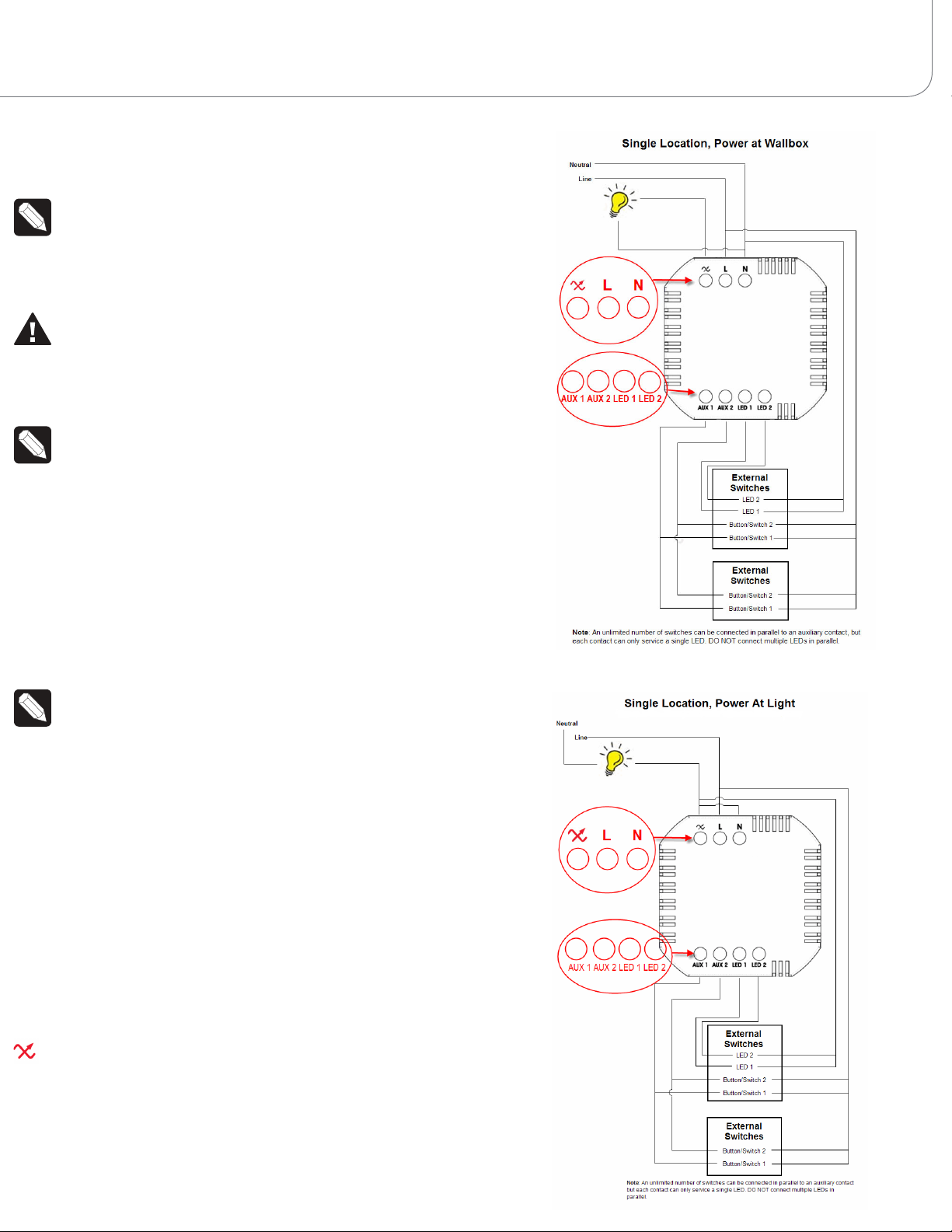
Figure 2. Single Location, Power at Wallbox
Installing the Puck Module Inside the Wallbox in a ‘Floating’
Position
NOTE: If local electrical code allows it, the Puck Module can be installed
inside the wallbox in a free floating manner. If the wallbox is deep enough,
this allows an external switch/keypad to be mounted to the wallbox in
front of the Puck Module.
1 Remove the Puck Module mounting ears (see Figure 1).
2 Fit the wires back into the wallbox. Fold the wires into a zigzag pattern so
that they easily fold into the wallbox
3 Push the Puck Module into the wallbox.
Finishing the Installation
1 When the wiring and installation are complete, turn on the mains power.
2 Test the Puck Module to see if it is working properly (see “Operation and
Configuration” on Page 2).
Sample Wiring Configurations
Figures 2, 3, 4, and 5 show wiring for a single or multiple locations.
—Load wire.
L—Line wire.
N—Neutral wire.
Aux 1, Aux 2—Auxiliary switch(es). Use Composer Pro to define the behavior.
LED 1, LED 2—220-240V indicator LEDs (lamps) on auxiliary switches. Use
Composer to define the behavior.
Figure 3. Single Location, Power at Light
(DO NOT use with Switch Puck or with fluorescent, CFL, or LED Loads)
Page 3

™
DO NOT use with Switch Puck or with fluorescent, CFL, or LED loads
Page 4

Operation and Configuration
1 The Puck Module must be identified and configured using the Control4
Composer software application. See the ComposerProUserGuide for
information about configuring the Puck Module.
2 To test/operate the Puck Module prior to configuration:
• PressandreleasetheIdentify button on the puck to toggle the load. With
a Puck Dimmer, pressing and holding the Identify button will ramp/fade
the load. The LED on the ID button will be lit when the load is on, and the
LED will be o when the load is o.
Figure 6. Puck Module with Button LED
• Both auxiliary contacts are configured to toggle the load by default. If a
keypad/switch is connected to an auxiliary contact, press and release the
button to toggle the load.
• The default behavior for both auxiliary LEDs is Load On = LED on, Load
O = LED O.
3 In the case of a short circuit or overload condition, the Puck Module has
built-in circuit protection that will put the module into a safe mode. When an
incandescent bulb burns out, it creates a momentary high-current situation
that can activate this protection. If the protection has been activated:
• The LED on the Puck Module and any LEDs on connected switches will
blink once every two (2) seconds.
• To reset the device:
• Click the ID button on the puck, OR
• Press and release the button connected to auxiliary Contact 1 (One).
• If the Puck Module goes back into safe mode after resetting, the fault
condition still exists and must be addressed before attempting to reset the
Puck Module again.
• When the Puck Module returns to safe mode within 10 seconds of a reset,
it cannot be reset by a single click of the ID button or auxiliary contact.
To reset the device in this case:
• Click the ID button on the puck 15 times, OR
• Press and release the button connected to auxiliary Contact 1 (One)
15 times.
4 Button tap sequences can be performed using either the button on the
Puck Module or the buttons attached to the auxiliary contact. When using
a latching switch, each toggle of the switch (up to down or down to up) is
treated as one (1) tap.
Troubleshooting
1 If the load does not turn on:
• Ensure that the circuit breaker is not turned o or tripped.
• Ensure that the light bulb is not burned out and is screwed in properly.
• Ensure that the Puck Module is not in short circuit safe mode. (See Step 3
in the “Operation and Configuration.”)
• Check for proper wiring (see “Sample Wiring Diagrams”).
2 If the button(s) connected to the auxiliary contacts do not operate the load,
check for proper wiring (see “Sample Wiring Diagrams”).
3 If the LEDs connected to the auxiliary LED terminals do not illuminate:
• Check for proper wiring (see “Sample Wiring Diagrams”).
• Ensure that the LEDs are designed to operate at 220-240V.
Regulatory/Safety Compliance
To review regulatory information for your particular Control4 products, see
the information located on the Control4 website at: http://www.control4.com/
regulatory/.
Patent Information
Protected under U.S. Patents 7,336,463 and licensed under U.S. Patents 5,905,442
and 5,982,103
Warranty
For complete warranty information, including details on consumer legal rights as
well as warranty exclusions, visit www.control4.com/warranty.
About this Document
Part Number: 200-00205 Rev B, 7/29/2011
Function Button on Puck Aux. Contact 1 Aux. Contacts
1 & 2
Identify 4 4 N/A
ZigBee Channel 7 7 N /A
Reboot Device 15 15 N/A
Factory Reset 9 22 9-4-9
Leave Mesh &
Reset
13 30 13-4-13
©2011 Control4. All rights reserved. Control4, the Control4 logo, the Control4 iQ logo and the Control4 certified logo are registered trademarks or trademarks of
Control4 Corporation in the United States and/or other countries. All other names and brands may be claimed as the property of their respective owners.
 Loading...