

Page 1
H.264 5-Megapixel
NVR Series
Quick Guide
Page 2

H.264 5-Megapixel Network Video Recorder Series Quick Guide
Page 1
About this document
This document includes instructions for basic operating the H264 5-Megapixel Series
Network Video Recorder.
Electromagnetic Compatibility (EMC)
This equipment generates, uses and can radiate radio frequency energy and, if not
installed and used in accordance with the instructions, may cause harmful interference
to radio communications. However, there is no guarantee that interference will not occur
in a particular installation.
If this equipment does cause harmful interference to radio or television reception, which
can be determined by turning the equipment off and on, the user is encouraged to try
to correct the interference by one or more of the following measures: Re-orient or
relocate the receiving antenna. Increase the separation between the equipment and
receiver. Connect the equipment to an outlet on a different circuit to the receiver.
Consult your dealer or an experienced radio/TV technician for help. Shielded (STP)
network cables must be used with this unit to ensure compliance with EMC standards.
Professional 2U 19” NVR / Lite 16CH NVR has been tested and found to comply with the
limits for a Class A digital device, pursuant to part 15 of the FCC Rules. These limits are
designed to provide reasonable protection against harmful interference when the
equipment is operated in a commercial environment. Operation of this equipment in a
residential area is likely to cause harmful interference in which case the user will be
required to correct the interference at his/her own expense.
Professional 1U 19” NVR has been tested and found to comply with the limits for a class
B digital device, pursuant to part 15 of the FCC Rules. These limits are designed to
provide reasonable protection against harmful interference in a residential installation.
Operation of this equipment in a residential area is likely to cause interference, in which
case the user at his/her own expense will be required to take whatever measures may be
required to correct the interference.
Page 3

H.264 5-Megapixel Network Video Recorder Series Quick Guide
CAUTION
Features
Standalone NVR
Supports 5-megapixel and 1080p 60 FPS H.264 IP cameras
Up to 6 Mbps incoming network throughput
Full HD 1080p HDMI and VGA output
Compatible with iOS and Android devices
Metadata can be embedded into videos
Supports Setup Wizard
HTML5 streaming multiple browser supported
P2P easy remote access supported
Caution
Do not drop or strike the equipment
Do not install the equipment near naked flames or heat sources
Do not expose this unit to rain, moisture, smoke or dusty environments
Do not cover the opening of the unit with cloth or plastic or install this unit in
Page 2
a poorly-ventilated place. Allow 10 cm between this unit and its surroundings
Do not continue to operate the unit under abnormal conditions such as
detection of smoke, strange smell, or malfunctioned screen whilst power is
turned on
Do not touch the power connection with wet hands
Do not damage the power cord or leave it under pressure
To avoid unnecessary magnetic interference, do not operate this unit near
magnets, speaker system, etc.
All connection cables must be grounded properly
RISK OF EXPLOSION IF BATTERY IS REPLACED WITH AN INCORRECT TYPE
DISPOSE OF USED BATTERIES ACCORDING TO THE INSTRUCTIONS
Page 4
H.264 5-Megapixel Network Video Recorder Series Quick Guide
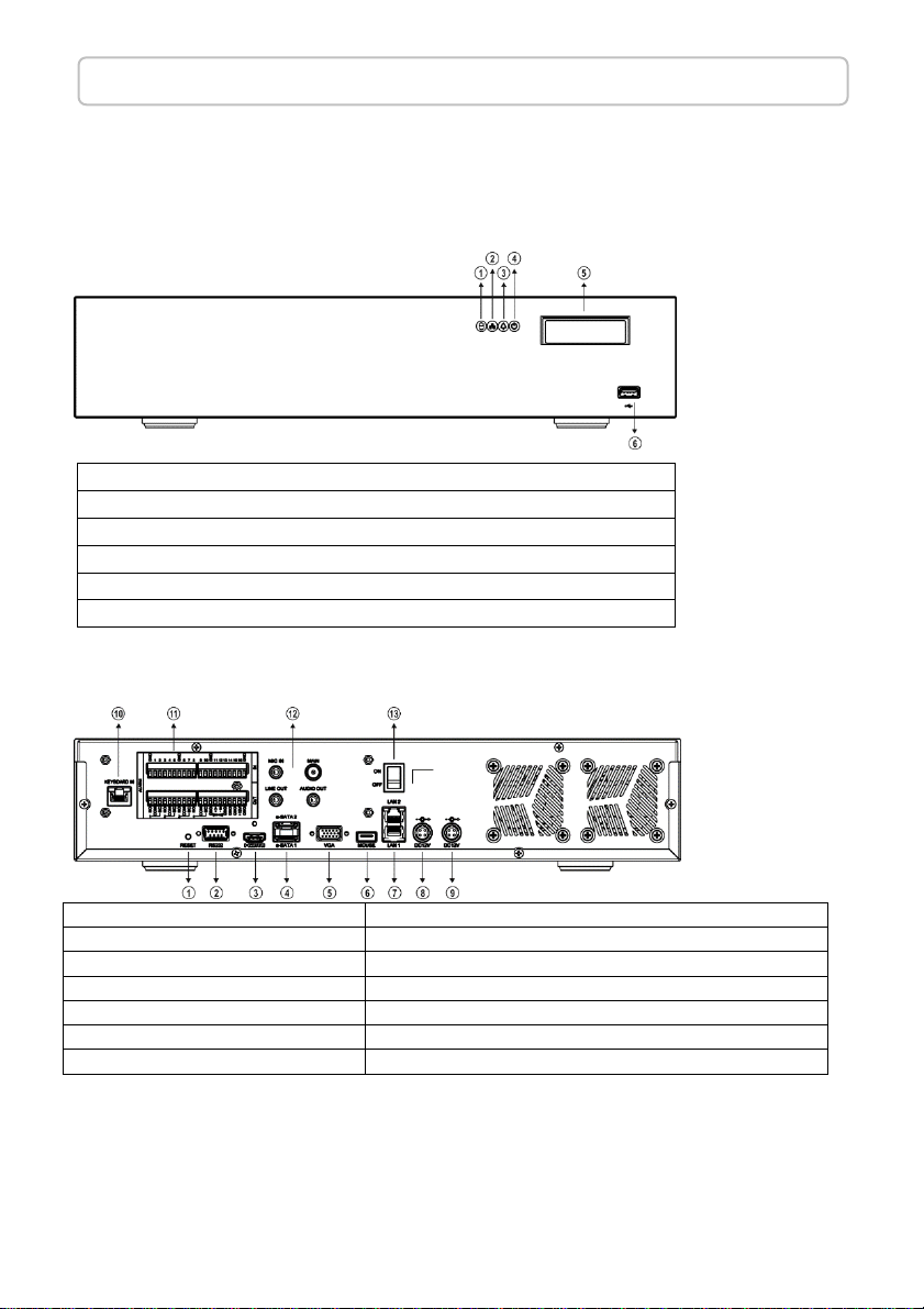
1. Hardware reset button
8.
Primary power socket
2. RS-232 connector
9.
Secondary power socket
3. HDMI output connector
10.
Keyboard
-
in connector
4. eSATA
connector
11.
DI/DO, RS
-
485, and DC 12 V output
5. VGA output connector
12.
MIC IN, LINE OUT, AUDIO OUT
,
MAIN
6. USB port
13.
Power switch
7. RJ-45 Gigabit connector
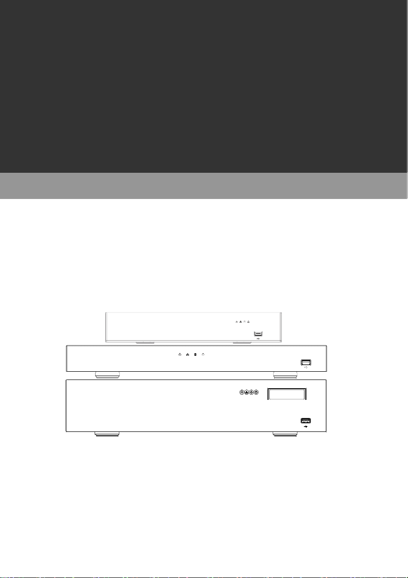
Product Overview
Page 3
Professional 2U 19”
8Bay Non-RAID NVR
Front View
1. HDD LED, green, blinking, HDD activity indicator
2. LAN LED, green, LAN activity indicator
3. ALARM LED, red, blinking, indicator of triggered alarms
4. POWER LED, amber, power on/off indicator
5. OLED, system activity information indicator
6. USB port
Rear View
Note:
When using the redundant power function, a one-minute pause is recommended after two
consecutive power switching to prevent damaging the transformer.
The total current of external devices connected to the 12 V power output must be under 1 A.
Page 5

H.264 5-Megapixel Network Video Recorder Series Quick Guide
1. VGA output connector
8.
eSATA connector
2. HDMI
output connector
9. RJ-
45 Gigabit connector
3. USB port
10.
DI/DO
4. Power switch
11.
Keyboard
-
in connector
5. P
ower socket
6. RJ-45 Gigabit connector
7. AUDIO OUT
Professional 1U 19” 4Bay Non-RAID NVR
Front View
1. POWER LED, amber, power on/off indicator
2. LAN LED, green, LAN activity indicator
3. HDD LED, green, blinking, HDD activity indicator
4. ALARM LED, red, blinking, indicator of triggered alarms
5. USB port
Rear View
Page 4
Page 6

H.264 5-Megapixel Network Video Recorder Series Quick Guide
Lite NVR Front View
Lite 16CH 4Bay NVR Rear View
Page 5
Lite 16CH 2Bay NVR Rear View
Page 7

H.264 5-Megapixel Network Video Recorder Series Quick Guide
Page 6
Hard Drives Installation Instructions
Professional 2U 19” 8Bay Non-RAID NVR Installation
Remove the upper casing and loosen the screws on both sides of the hard drive bracket to remove it.
Install hard drives and tighten the hard drive screws as instructed in the image below.
Screws loosened Screws tightened
Properly connect the SATA cables and power cables to the connectors following the instruction
below:
H2&H3 > J30, H1&H4 > J31, H5&H8 > J50, H6&H7 > J51
Finally, complete the hard drive installation by closing the upper casing and tightening the screws.
Page 8

H.264 5-Megapixel Network Video Recorder Series Quick Guide
Page 7
Beginning using the NVR
You will see the following screen through HDMI or VGA connection once you power on the NVR:
The information shown on the top of the screen is described as followed:
0.00 / 1000 (100) Mbps:
The left side of the slash is the combined transmission rate of all channels, and the right side your
network speed.
HDD 1 (2):
Shows the current number of hard drive being used for recording and the storage capacity used.
P➊ ➋ :
Shows the power source used currently.
Note: This information is available depending on models.
Move your cursor slightly to display the NVR controls (as shown in the image below):
Page 9

H.264 5-Megapixel Network Video Recorder Series Quick Guide
At the upper-left corner of the screen is the NVR controls, which are, from left to right:
NVR SETTINGS, FREEZE, ALARM EVENT, PLAYBACK/BACKUP ,
SCHEDULE, and MANUAL Recording.
Page 8
NVR SETTINGS
If you access the NVR SETTINGS for the first time, you will see Setup Wizard on the screen as
below, which provides you with quick configurations for the NVR, including language, password,
date, time, storage, network, P2P, and camera. Please follow the instructions to finish necessary
setup and start recording. To prevent the wizard from appearing again, be sure to check No longer
use Setup Wizard. To run Setup Wizard manually, go to NVR SETTINGS> SYSTEM >
MAINTENANCE, and click Run to start Setup Wizard.
Page 10

H.264 5-Megapixel Network Video Recorder Series Quick Guide
Page 9
FREEZE
Click to freeze the real-time video, and the icon will be highlighted in blue when the video is frozen.
ALARM EVENT
Click to enter the ALARM EVENT screen, where the options include MOTION/SENSOR/MANUAL
EVENT.
Then, click the drop-down menu at the top to sort the events by date or channel. Double-click an
event log of your choosing, or choose an event before clicking Playback at the upper-right corner of
the screen to view or back up the selected video clip. Click any event before choosing USB or E-mail
to export the video to a storage device or send notification email to a pre-determined email address.
PLAYBACK/BACKUP
Click to enter the following screen for playback and backup. You can expand and collapse the upper
timeline by YEAR, MONTH, DAY, HOUR, and MINUTE. On the upper timeline, drag and select the
time you want to start playing recorded video; drag from the timeline at the bottom of the screen to
select the backup range. For more details, please refer to the NVR user manual in the CD included in
the box.
Page 11

H.264 5-Megapixel Network Video Recorder Series Quick Guide
Page 10
/ SCHEDULE/MANUAL RECORDING
Indicates whether the current recording setting is scheduled recording or manual recording. Click
the icon to switch.
Below shows the controls at the bottom of the screen:
/ :
Indicates whether the current split-screen controls are for HDMI or VGA.
Note: This information is available depending on models.
Below shows the controls for the number of split-screens:
:
Controls for the number of split-screens.
:
Click to broadcast your message through a microphone.
:
Click to activate the sequential mode, which will show videos channels in the order you specify.
Page 12

H.264 5-Megapixel Network Video Recorder Series Quick Guide
Page 11
:
Click to activate a specific DO output.
Note: This function is available depending on models.
BASIC NVR SETTINGS
If you skipped Setup Wizard, you need to change some basis settings before starting to record.
Set up Display Language
In NVR SETTINGS, click the gear icon at the upper-right corner to switch system display language.
Format Hard Drives
In NVR SETTINGS > SYSTEM > STORAGE > HDD MGT., select the device to format and click
Format.
Adjust Date Time
In NVR SETTINGS > SYSTEM > TIME, make sure system time is correctly set.
Configure Network Environment
In NVR SETTINGS > NETWORK > GENERAL, enter the required information such as IP Mode, IP
Address, Subnet Mask, Default Gateway, Primary DDNS, etc. according to your network
environment.
Connect to Cameras
In NVR SETTINGS > CAMERA > GENERAL, click WS-Discovery to start searching for cameras in
the local network. Select a camera from list, and click Select to show the camera feed on the
corresponding channel. Click Apply for the changes to take effect.
Start to Record
To activate continuous recording, make sure the desired channel’s Record Mode in NVR SETTINGS
> RECORD > GENERAL is set to Schedule; Schedule Table in NVR SETTINGS > RECORD >
SCHEDULE is set to Always; Overwritten in NVR SETTINGS > RECORD > ADVANCE is set to On.
Note: For more details, please refer to the NVR user manual in the CD included in the box.
Page 13

DISTRIBUTOR:
66-NVR5M264OOE-3
 Loading...