

Page 1

Network Video Recorder User Manual
Table of Contents
About this document .................................................................................................................................. 3
Disclaimer .................................................................................................................................................. 3
Caution ....................................................................................................................................................... 3
Introduction ................................................................................................................................................ 4
Features ..................................................................................................................................................... 4
Trademarks and registered trademarks ..................................................................................................... 4
Chapter 1 Getting Started .......................................................................................................................... 5
Chapter 1-1 NVR Settings Quick Guide..................................................................................................... 6
Chapter 1-2 Freeze .................................................................................................................................... 7
Chapter 1-3 Alarm Event............................................................................................................................ 7
Chapter 1-3-1 Motion / Sensor Event ........................................................................................................ 7
Chapter 1-3-2 Manual Event ...................................................................................................................... 8
Chapter 1-4 Playback / Backup ................................................................................................................. 9
Chapter 1-4-1 Playback ............................................................................................................................. 9
Chapter 1-4-2 Backup .............................................................................................................................. 10
Chapter 2 System Setup .......................................................................................................................... 11
Chapter 2-1 General ................................................................................................................................ 11
Chapter 2-2 Time ..................................................................................................................................... 12
Chapter 2-3 User ...................................................................................................................................... 12
Chapter 2-4 Storage ................................................................................................................................. 13
Chapter 2-4-1 HDD MGT ( Raid NVR ) .................................................................................................... 14
Chapter 2-4-2 S.M.A.R.T. ........................................................................................................................ 17
Chapter 2-4-3 USB MGT.......................................................................................................................... 17
Chapter 2-5 Event .................................................................................................................................... 18
Chapter 2-5-1 System .............................................................................................................................. 18
Chapter 2-5-2 Operating .......................................................................................................................... 18
Chapter 2-6 Maintenance......................................................................................................................... 18
Chapter 3 Network Setup ......................................................................................................................... 19
Chapter 3-1 General ................................................................................................................................ 19
Chapter 3-2 Advance ............................................................................................................................... 20
Chapter 3-2-1 TCP/IP .............................................................................................................................. 20
Chapter 3-2-2 Mobile ............................................................................................................................... 20
Chapter 3-2-3 P2P ................................................................................................................................... 20
Chapter 3-2-4 Wi-Fi .................................................................................................................................. 21
Chapter 3-2-5 Bonding ............................................................................................................................. 21
Chapter 3-3 E-Mail ................................................................................................................................... 22
Chapter 3-4 FTP ...................................................................................................................................... 23
Chapter 3-5 DDNS ................................................................................................................................... 24
Chapter 3-6 Other .................................................................................................................................... 24
Chapter 3-6-2 SNMP ................................................................................................................................ 25
Chapter 4 Camera Setup ......................................................................................................................... 25
Chapter 4-1 General ................................................................................................................................ 26
Chapter 5 Record Setup .......................................................................................................................... 27
Chapter 5-1 General ................................................................................................................................ 27
Chapter 5-2 Schedule .............................................................................................................................. 28
Chapter 5-3 Advance ............................................................................................................................... 28
Chapter 6 Alarm Setup............................................................................................................................. 28
Chapter 6-1 General ................................................................................................................................ 29
Chapter 6-2 Motion Area .......................................................................................................................... 29
Chapter 6-3 Output .................................................................................................................................. 29
Chapter 6-3-1 Alarm Led.......................................................................................................................... 29
1 66-UM-NVR3-OOE-1
Page 2

Chapter 6-3-2 Buzzer ............................................................................................................................... 30
Chapter 6-3-3 E-Mail ................................................................................................................................ 30
Chapter 6-3-4 FTP ................................................................................................................................... 30
Chapter 6-3-5 Notification ........................................................................................................................ 31
Chapter 6-3-6 DO#1–N (manual DO control) .......................................................................................... 31
Chapter 7-1 General ................................................................................................................................ 31
Chapter 7-2 Advance ............................................................................................................................... 32
Chapter 7-3 Sequence ............................................................................................................................. 32
Chapter 8 PTZ Setup ............................................................................................................................... 33
Chapter 8-1 General ................................................................................................................................ 33
Chapter 8-2 NVR Cascade ...................................................................................................................... 33
Chapter 9 Metadata Setup ....................................................................................................................... 34
Chapter 9-1 General ................................................................................................................................ 34
Chapter 9-2 Event .................................................................................................................................... 35
Chapter 10 Other Setup ........................................................................................................................... 35
Chapter 10-1 Smartphone ....................................................................................................................... 36
Chapter 10-2 IVS ..................................................................................................................................... 36
Chapter 11 Stream ................................................................................................................................... 36
Chapter 11-1 Live ..................................................................................................................................... 37
Chapter 11-2 Play .................................................................................................................................... 37
Chapter 11-3 Backup ............................................................................................................................... 38
Appendix .................................................................................................................................................. 39
Install IPCamPlus ..................................................................................................................................... 39
For Android Users .................................................................................................................................... 39
For iOS User ............................................................................................................................................ 40
2 66-UM-NVR3-OOE-1
Page 3
CAUTION
RISK OF EXPLOSION IF BATTERY IS REPLACED WITH AN
INCORRECT TYPE.
About this document
This document includes instructions for operating the Network Video Recorder Series.
Disclaimer
Please be aware that this user manual may cover a range of product specifications for various models.
Characteristics and features discussed and/or illustrated in this manual may not be applicable or
available to all models. We reserve the right to change product specifications, designs and equipment
without notice and without incurring obligation.
Caution
Do not drop or strike the equipment
Do not install the equipment near naked flames or heat sources
Do not expose this unit to rain, moisture, smoke or dusty environments
Do not cover the opening of the unit with cloth or plastic or install this unit in a poorly-ventilated
place. Allow 10cm between this unit and its surroundings
Do not continue to operate the unit under abnormal conditions such as detection of smoke,
strange smell or no display on screen whilst power is turned on
Do not touch the power connection with wet hands
Do not damage the power cord or leave it under pressure
To avoid unnecessary magnetic interference, do not operate this unit near magnets, speaker
system, etc.
All connection cables must be grounded properly
3 66-UM-NVR3-OOE-1
Page 4

Introduction
The NVR Series are network video recorders that offer a standalone solution for managing IP cameras
and systems. The built-in high-quality decoder can deliver 5MP/ 3MP/ 1080p/ 1.3M/ 1M/ 960H/ 720p/
D1/ VGA/ CIF IP camera streams. Each channel can be individually configured to record in SD or HD
resolution to suit your needs.
The internal HDMI and VGA engine supports adaptive motion refinement technology, which provides
HDMI and VGA output with 1080p resolution. The NVR Series can be easily installed in all environments
through the TCP/IP network, and the support of IPScan utility and Web Services Dynamic Discovery
(WS-Discovery) protocol allows for locating all the cameras on the network and can generate a preview
thumbnail of each channel. The self-diagnostic feature can estimate remaining recording time and
monitor S.M.A.R.T status, network status, and other information.
Files recorded by the NVR can be exported to DVD and USB flash drive, or the files can be downloaded
via Backup Manager, Remote Player, FTP client software, or Network Places. Mobile support for iOS,
and Android allows for remote viewing of connected cameras at high frame rates. Browser-based live
monitoring and video playback features are also supported.
The NVR also supports external METADATA device, such as POS, ATM, GPS, etc. METADATA can be
embedded within videos and saved as a database where you can search for METADATA history
according to content, date, and time.
Features
Standalone NVR
Supports up to 5MP and 1080p 60 FPS IP cameras
HDMI and 1080P VGA output
Compatible with iOS and Android devices
Metadata can be embedded into videos
Supports Setup Wizard
HTML5 streaming multiple browser supported
P2P easy remote access supported
Trademarks and registered trademarks
Microsoft, Windows, Internet Explorer are registered trademarks of Microsoft
and/or other countries.
Adobe and Adobe PDF are registered trademarks of Adobe Systems Incorporated in the U.S and/or
other countries.
JavaScript and all Java-based trademarks and logos are trademarks or registered trademarks of Sun
Microsystems, Inc. in the U.S and/or other countries.
Linux, Macintosh, and Mozilla are registered trademarks of the respective holders.
Other names of companies and their products mentioned in this manual may be trademarks or
registered trademarks of their respective owners.
Corporation in the U.S
4 66-UM-NVR3-OOE-1
Page 5
Chapter 1 Getting Started
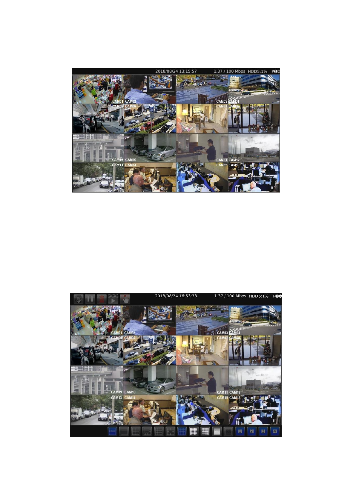
You will see the following screen through HDMI or VGA connection once you power on the NVR:
The information shown on the top of the screen is described as follows:
0.00 / 1000 (100) Mbps: The left side of the slash is the combined transmission rate of all
channels, and the right side network speed.
HDD (1):(2)%: (1) shows the current number of hard drive being used for recording. (2) storage
capacity used.
P: Shows the power source currently used.
Note: This information is available depending on models.
Move mouse cursor slightly to display the NVR controls (as shown in the image below):
5 66-UM-NVR3-OOE-1
Page 6
Icons
Description
Indicates whether the current split-screen controls are for HDMI
or VGA.
Note: Available only when VGA Spot mode is on
Controls for the number of split-screens.
Click to broadcast your message through a microphone.
Click to activate the sequential mode, which will show videos
channels in the order you specify.
Click to activate a specific DO output.
Icons
Description
NVR Settings
Freeze
Alarm Event
Playback / Backup
Schedule
Manual Recording
Below controls can be seen at the bottom of the screen:
Note: This information is available depending on models.
Below are NVR controls that are at the upper-left corner of the screen:
Chapter 1-1 NVR Settings Quick Guide
If you access the NVR SETTINGS for the first time, you will see Setup Wizard on the screen as below,
which provides you with quick configurations for the NVR, including language, password, date, time,
storage, network, P2P, and camera. Please follow the instructions to finish necessary setup and start
recording. To prevent the wizard from appearing again, be sure to check No longer use Setup Wizard.
Whenever you want to run Setup Wizard again, go to NVR SETTINGS> SYSTEM > MAINTENANCE,
and click Run to start Setup Wizard.
6 66-UM-NVR3-OOE-1
Page 7
Or, you may see the setting menu below:
Note: Click the gear icon at the upper-right corner of the screen to change the NVR language.
Chapter 1-2 Freeze
Click to freeze the real-time video, and the icon will be highlighted in blue.
Chapter 1-3 Alarm Event
Click to enter the ALARM EVENT page.
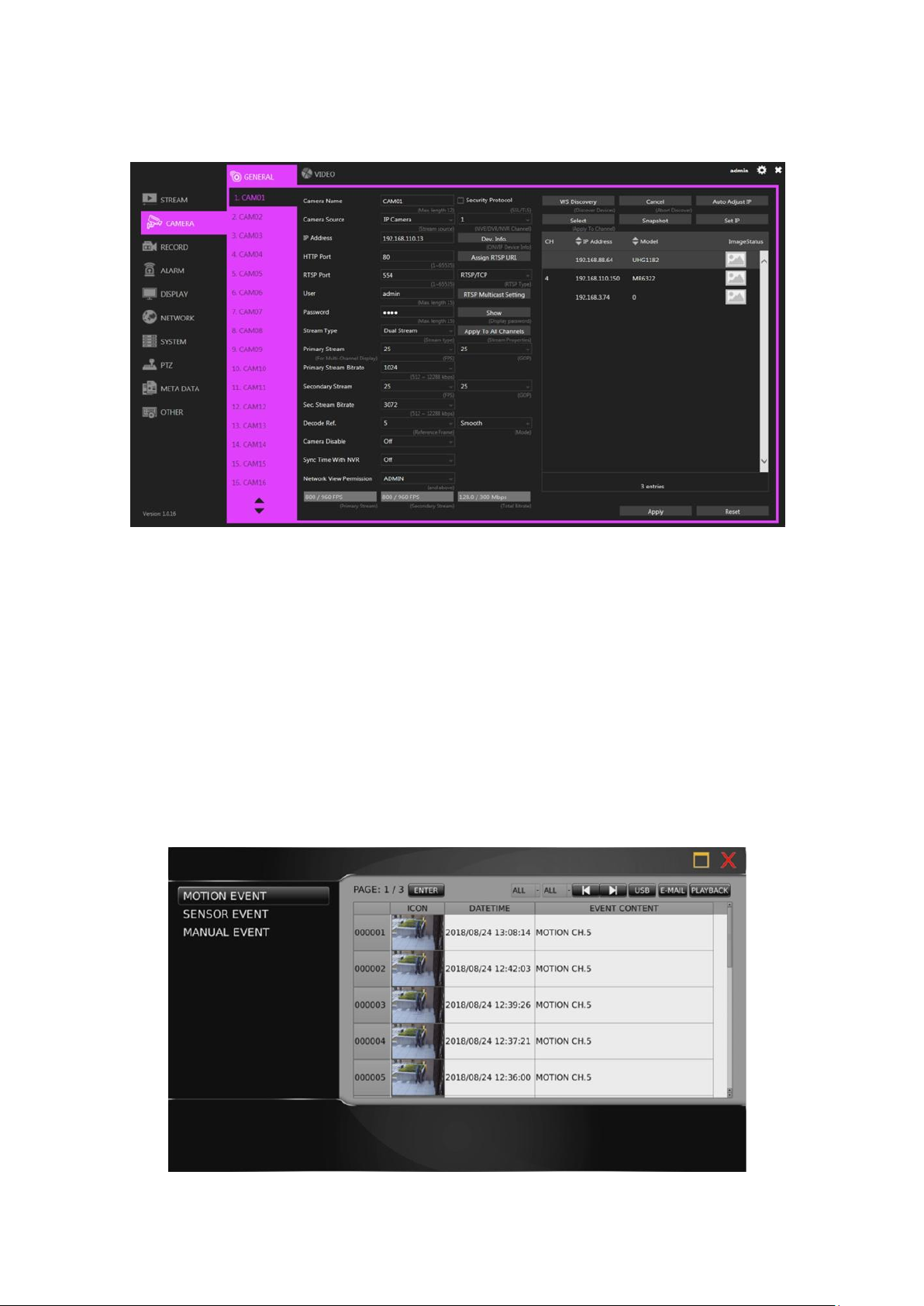
Chapter 1-3-1 Motion / Sensor Event
If the motion detection function is enabled for your camera, any motion alarms triggered will be recorded
in motion event history, and the sensor alarms triggered in the sensor event history (as shown in the
images below).
7 66-UM-NVR3-OOE-1
Page 8
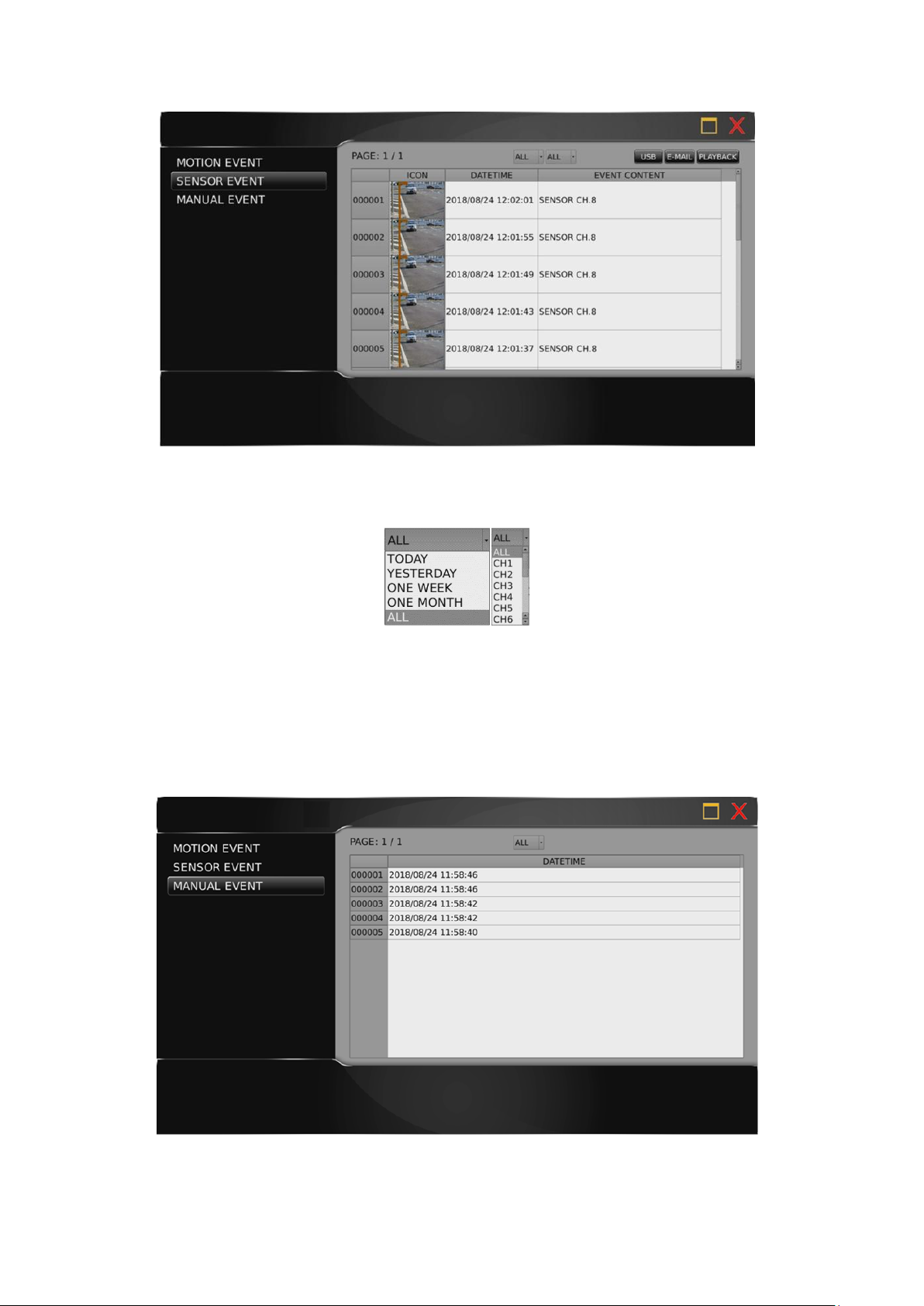
Press the drop-down menu at the top to sort the alarm events by date or channel (as shown in the
image below).
Press USB to back up snapshot in USB storage, press E-MAIL to send a snapshot via e-mail, or press
PLAY to view recorded video.
Chapter 1-3-2 Manual Event
When the recording mode is switched from Schedule to Manual, a record entry will be saved here (as
shown in the image below).
8 66-UM-NVR3-OOE-1
Page 9
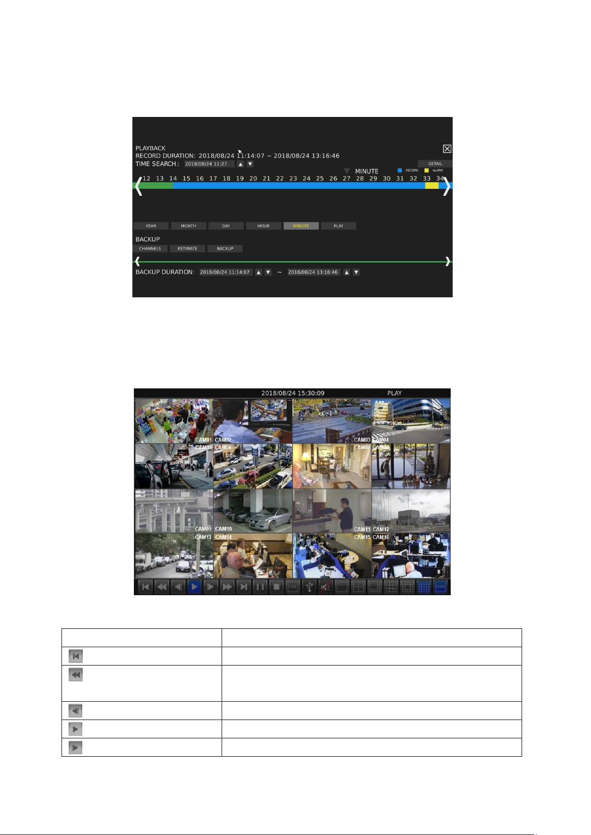
Icons
Description
Step Backward
Rewind: click repeatedly to adjust the speed of respective actions
(up to 64x)
Slow Rewind
Play
Slow Forward
Chapter 1-4 Playback / Backup
Click to enter the PLAYBACK/BACKUP page as shown below.
Chapter 1-4-1 Playback
You can expand and collapse time line by year, month, day, hour, and minute. On the upper timeline
drag and select the time you want to start playing recorded video or alarm video to enter the Playback
as following screen:
Details of the controls at the bottom of the PLAYBACK screen are described as follows:
9 66-UM-NVR3-OOE-1
Page 10
Fast Forward: click repeatedly to adjust the speed of respective
actions (up to 64x)
Step Forward
Pause
Click to return to the PLAYBACK/BACKUP screen.
Click to return to live video
Click to export the recorded video to a USB device.
Click to turn on/off sound
Choose the number of split-screens according to your needs
Indicates whether the current split-screen controls are for HDMI
or VGA
Note: This information is available depending on models.
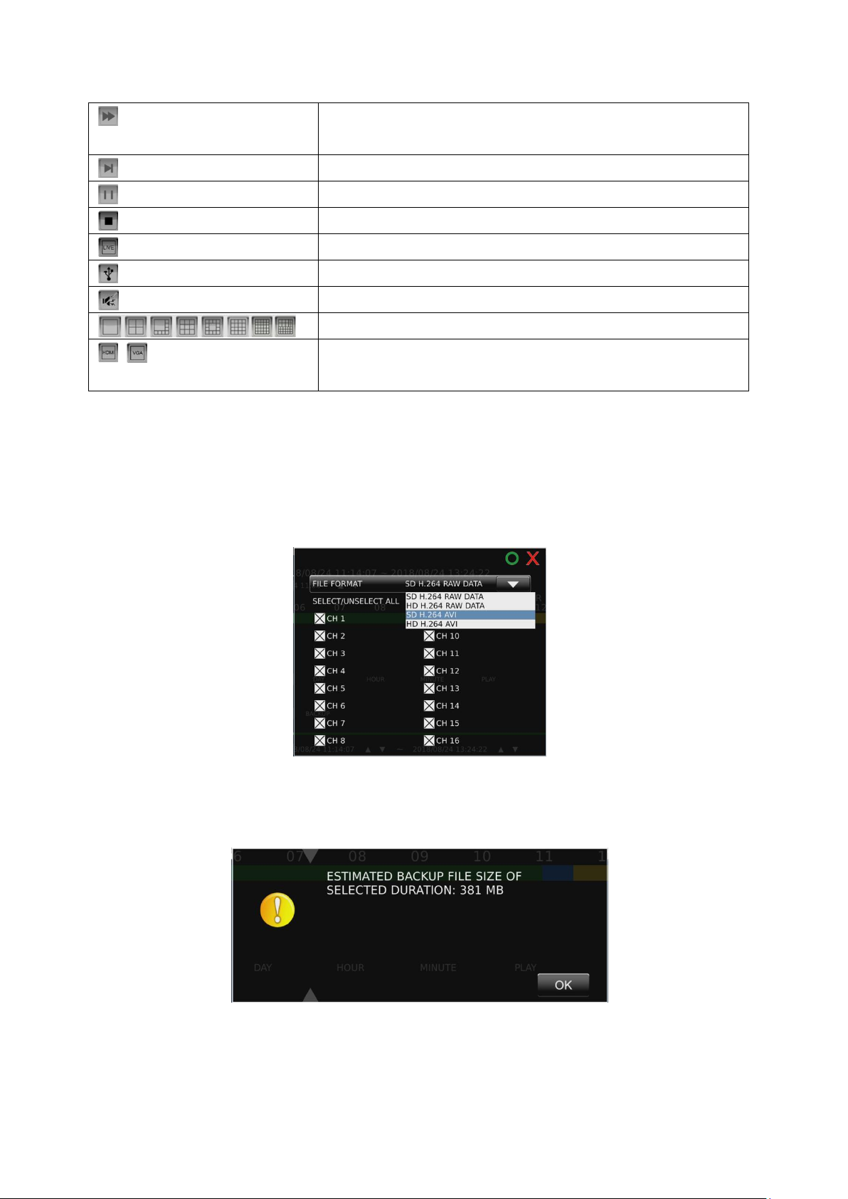
Chapter 1-4-2 Backup
If you need to back up recorded files, click and drag the timeline at the bottom of the screen to select
the backup range. Press CHANNELS to show the FILE FORMAT/CHANNELS SELECT dialog (as
shown in the below image), where you can choose the channel(s) to back up and file format:
Choose ESTIMATE to show the BACKUP FILE SIZE ESTIMATE dialog:
10 66-UM-NVR3-OOE-1
Page 11
Choose BACKUP to show the DEVICE/EXECUTE dialog:
You may determine to back up the video in DVD, USB storage device, or the temporary space of the
NVR.
/ SCHEDULE/MANUAL: Indicates whether the current recording setting is scheduled
recording or manual recording. Click to switch.
Chapter 2 NVR Settings
Chapter 2 System Setup
Click to enter NVR SETTINGS and click SYSTEM in the left pane, where you are
allowed to adjust system configurations of the NVR. The details of the tabs are described as follows:
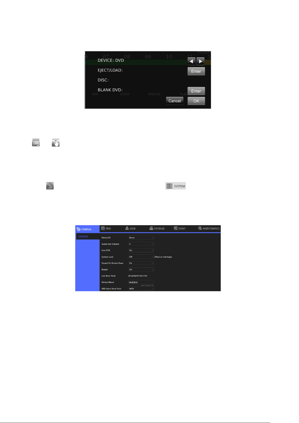
Chapter 2-1 General
Device ID: Assign an ID for the NVR to be controlled by the remote controller.
Audio Out Volume: Adjust the volume of the NVR.
Live OSD: On, off, or no camera name.
System Lock: Switch on/off the system lock.
Sound On Button Press: Switch on/off the sound when pressing remote control buttons.
Buzzer: Switch on/off the sound when an alarm is triggered.
Last Boot Time: Shows the last time the system is rebooted.
Power Supply Status: Shows the status of the power supply currently in use.
Note: This information is available depending on models.
Line Out Volume: Adjust the audio volume.
RS-232: Press Test to test the functionality of the RS-232 port.
Note: This information is available depending on models.
11 66-UM-NVR3-OOE-1
Page 12
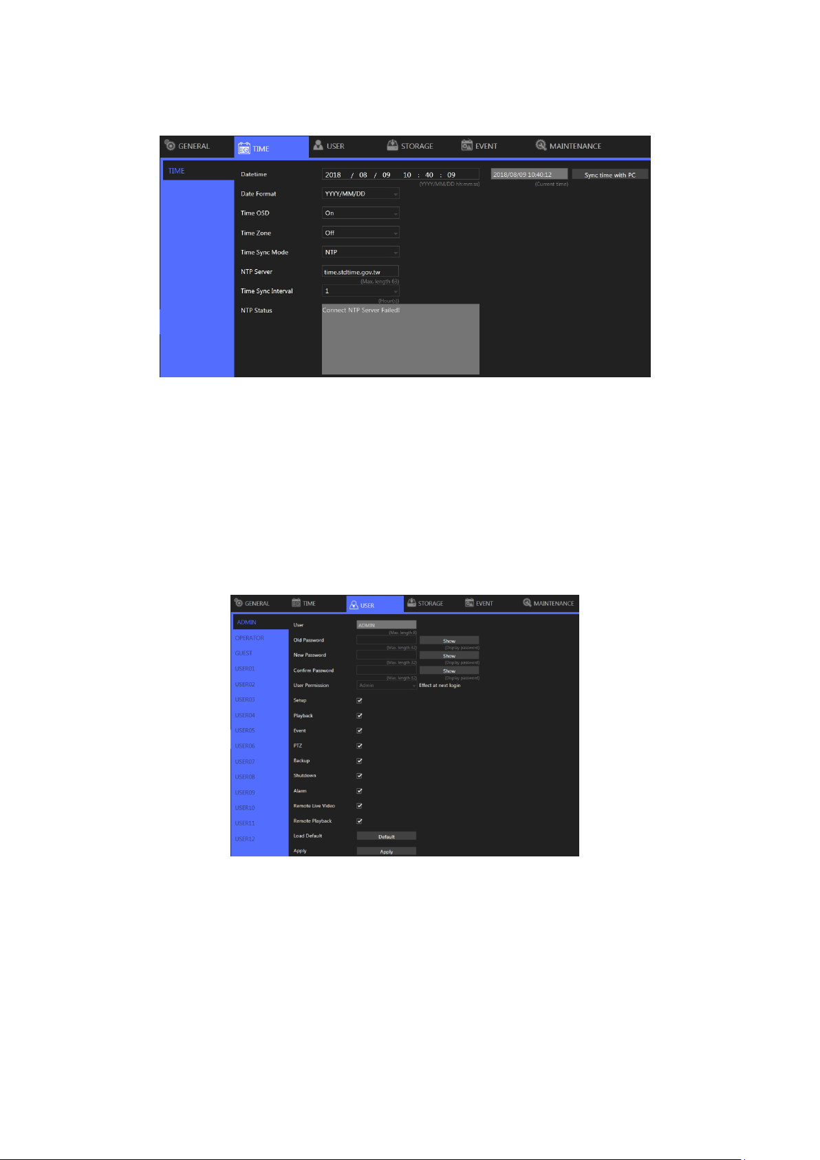
Chapter 2-2 Time
Date/Time: Set the date/time of the NVR.
Date Format: Modify the date display format.
Time OSD: Switch on/off the time to be displayed on the screen.
Time Zone: Change the time zone of the location where the NVR is installed.
Time Sync Mode: Choose how you would like the time to be synced.
NTP Server: Enter the NTP server you want to use.
Time Sync Interval: Choose the interval for the time to be synced.
NTP Status: The status of connection to selected NTP server will appear here.
Chapter 2-3 User
The NVR supports up to 15 sets of individual user settings (including default user administrator, operator,
and guest), to which you can assign different access privileges.
User: Enter the name of the user (applicable only to User01–12).
Old Password, New Password, and Confirm Password: If you would like to change the
password, enter your previous password and enter the new password and confirm the
password. Press Show to reveal the password. The default passwords for administrator,
operator, and guest are 1111, 2222, and 3333, respectively.
User Permission: Set the access privileges of the user to administrator, operator, or guest.
Load Default: Restore to the default settings.
12 66-UM-NVR3-OOE-1
Page 13

Chapter 2-4 Storage
HDD MGT ( Non-RAID NVR )
In HDD MGT.( Non RAID NVR ), there are HDD format, file system defrag, check HDD malfunctioned
blocks, and HDD periodic inspection. Select a desired HDD and click Format, File System Defrag,
Bad Block Check, or Regular Check.
Regular Check:
Allows you to set the interval between system checks:
Parameters: Click each device to enter the screen below.
System Reserve Ratio allows you to allocate the percentage of HDD space that will not be occupied by
recorded files. In Mount Option, choose the writing mode for the hard drive.
13 66-UM-NVR3-OOE-1
Page 14

Chapter 2-4-1 HDD MGT ( Raid NVR )
In HDD MGT.( RAID NVR ), able to create RAID, delete RAID, format, defrag, check HDD
malfunctioned blocks and HDD periodic inspection, allow recording with single HDD(s) or RAID group.
Create RAID:
Click Create RAID to pop-up a HDD list dialog as below, the dialog list all HDD that free to use for
building a RAID group.
Select desired HDD, then choose available RAID level and click Create RAID to build, after building
process finished, there will be a new RAID group that show in the HDD MGT..
14 66-UM-NVR3-OOE-1
Page 15

Select desired RAID then click Format to format or click Delete RAID to delete.
Note:
1. The limitation size for each RAID group is 16TB.
2. For more detail about RAID level, please refer to https://en.wikipedia.org/wiki/RAID
3. Availability depends on models.
For details about File System Defrag, Bad Blocks Check, Regular Check please refer to the
descriptions above.
Note: When HDD error happened, raid’s status will change to degrade.
15 66-UM-NVR3-OOE-1
Page 16

Unmount All HDD(s)
Mount All HDD(s)
Add HDD to RAID(s)
16 66-UM-NVR3-OOE-1
Page 17

Add success
Chapter 2-4-2 S.M.A.R.T.
The S.M.A.R.T. status of your hard drive is displayed in S.M.A.R.T., where you can run analysis (either
short or extended) on the HDD. Choose between Short or Extended analysis and click Analysis to
start the process. You will see HDD status, information, attributes, and event history under HDD
S.M.A.R.T. Information.
Chapter 2-4-3 USB MGT.
Connect a USB device (flash drive or hard drive) to the NVR, and check the one you want to format
under this page, and then click Format.
17 66-UM-NVR3-OOE-1
Page 18

Chapter 2-5 Event
Chapter 2-5-1 System
The search field in this page allows you to search for specific event reports at different time and of
different content. Press Download to export the event report, Reload to update.
Chapter 2-5-2 Operating
You can examine the operating status of different users under this page. Press Download to export the
event report, Reload to update.
Chapter 2-6 Maintenance
Firmware Update: Choose a firmware file and click Update to proceed firmware update.
Export Settings: Click Export to copy system settings to a USB flash drive.
Import Settings: Click Import to apply a system setting that is stored in the plugged USB flash
drive.
Factory Reset: Click Reset to restore the system to the factory settings.
18 66-UM-NVR3-OOE-1
Page 19

Soft Reboot: Click to soft reset the system.
Watchdog Test: Click to test the system watchdog function. This will reboot the NVR.
Kernel Version: The kernel version of the system.
Setup Wizard: Click to execute the quick setup wizard.
Support: Click to open server execution log options dialog, record system execution details.
Chapter 3 Network Setup
Click to enter NVR SETTINGS, and click NETWORK in the left pane.
Chapter 3-1 General
Enter the required information in the fields:
IP Mode: Select the connection type of the NVR from Static, DHCP, and PPPoE.
IP Address: Enter the IP address you want to use, and press IP Test if necessary.
Subnet Mask: Enter the desired subnet mask.
Default Gateway: Enter the desired default gateway.
Primary DNS: Enter the first priority DNS server.
Secondary DNS: Enter the secondary DNS server in case the primary DNS is not available.
Video Port: Specify a desired video port.
HTTP Port: Specify a desired HTTP port.
FTP Port: Specify the desired FTP port.
MAC: This is the MAC address of your NVR.
PPPoE Account: If you choose to connect through PPPoE, enter the account name here.
PPPoE Password: Enter the required password for PPPoE connection.
PPPoE IP: Your PPPoE IP will be displayed here.
Hotspot IP: Your hotspot IP will be displayed here.
Note: When connected to an Android device via a USB connector, please turn on the USB tethering
function to assign a hotspot IP to the NVR.
19 66-UM-NVR3-OOE-1
Page 20

Chapter 3-2 Advance
Chapter 3-2-1 TCP/IP
NVR supports three sets of virtual IP addresses. When TCP/IP is switched On, the NVR can access the
camera or another NVR using the specific IP.
Chapter 3-2-2 Mobile
The NVR is compatible with several mobile data adapters (D-Link DWM-221, HUAWEI E3372h,
ALCATEL L800, etc.). Plug in the device and adjust the settings below.
Enable: Choose On to activate the service.
SIM PIN Code: Enter the PIN of the SIM card you use to connect to the mobile network.
IP Mode: The connection status of your mobile network.
IP Address: The IP address of your connection.
Signal Strength: The signal strength of your connection.
Chapter 3-2-3 P2P
20 66-UM-NVR3-OOE-1
Page 21

Note:
1. You can purchase a P2P account from your dealer.
2. Availability depends on models.
3. When activated successfully, a QR code will appear on the screen, and you can access the NVR
with a dedicated App by scanning the QR code.
Enable: Choose On to activate the service.
P2P Account: Enter your account ID.
P2P License: Enter your license code.
Chapter 3-2-4 Wi-Fi
The NVR is compatible with several Wifi dongle( EDIMAX EW-7811Un, ASUS USB-N13, TP-LIINK TLWN822M, Bointec CUB811K or others with 8192cu/mt7601cu chip set etc. )
Enable: Choose On to activate the service.
SSID: Service set identifier, enter required network name.
Password: Enter the password that you use to connect to the WiFi host.
IP Mode: Choose STATIC or DHCP to suit your WiFi network.
IP Address: DHCP chosen, display assigned IP address, STATIC enter required IP address.
Subnet Mask: DHCP chosen, display assigned subnet mask, STATIC enter required subnet
mask.
Default Gateway: DHCP chosen, display assigned gateway, STATIC enter required gateway
address.
Chapter 3-2-5 Bonding
Choose Redundancy or Sharing mode for dual Ethernet NVR.
Note: Availability depends on models.
21 66-UM-NVR3-OOE-1
Page 22

Chapter 3-3 E-Mail
When an alarm is triggered, the NVR can automatically send e-mail notifications to the recipients you
designated. The setting options are described below:
Send E-Mail: Check the box to enable sending e-mail notifications when an alarms is triggered.
E-Mail List: The list shows all saved e-mail addresses.
Edit Contact: Enter the email address you want to save as contacts and click Modify.
Authorization: Check if your e-mail account requires login authorization.
SSL/TLS: Check if your e-mail sever requires encryption.
E-Mail Account: Enter the account name of your e-mail.
E-Mail Password: Enter the password of your e-mail.
Sender: Enter the name you would like to display in the e-mail.
E-Mail Host: Enter the IP address of your e-mail server.
Port: Enter the port of your e-mail server.
JPEG File: Check to also attach JPEG photos when an alarm is triggered.
Candidate: Choose an email address and press Down or Up arrows to add contacts as
recipients.
Receiver: The list of recipient(s).
Annotation: Content of the email notification.
Trigger Conditions: Designate when to send the notification email by Channel Events and
System Events.
Channel Events: Click to open the dialog below.
Note: How many channels depend on models
22 66-UM-NVR3-OOE-1
Page 23

Motion: Check to send e-mail when movements are detected.
Alarm: Check to send e-mail when external alarms are set off.
Video Loss: Check to send e-mail when connection with IP Camera is lost.
System Events: Click to open the dialog below.
S.M.A.R.T. Err: Check to send E-Mail when an S.M.A.R.T. error is detected.
HDD Err: Check to send E-Mail when an HDD error is detected.
E-Mail Test: Click to send the testing email to verify out the settings.
Chapter 3-4 FTP
When an alarm is triggered, the NVR can automatically send snapshots to the FTP server you
designated. The setting options are described below:
FTP Server: Enter the IP address of the FTP server.
Port: Enter the port of the FTP server.
Account: Enter the account name of the FTP server.
Password: Enter the password of the FTP server
Prefix & Postfix: Specify the prefix and postfix of snapshot files.
File Name Format: Change the file name format to suit your need.
Check the cameras that you want to send notifications to the FTP when an alarm is triggered, and
specify the folder name where the images are saved.
For details about Trigger Conditions and Channel Events, please refer to the descriptions above.
23 66-UM-NVR3-OOE-1
Page 24

Chapter 3-5 DDNS
With DDNS, you can access an NVR connected to the Internet through the DDNS URL, whatever the
actual IP is. The setting options are described below:
Server: Choose the DDNS server you want to use.
Hostname: Enter the hostname of the DDNS server.
User: Enter the username to log in to the DDNS server.
Password: Enter the password to log in to the DDNS server.
WAN IP: Enter your WAN IP if the NVR cannot automatically get the correct address.
Check Interval: Choose the time interval you want the system to check theDDNS connection.
Note: The DDNS feature requires Internet connection.
Chapter 3-6 Other
The NVR also supports other protocols such as UPnP and SDDP, and related configurations can be
modified in the OTHER tab. The setting options are described below:
UPnP Device Name: The device name shown on the UPnP network.
UPnP Service: Switch on/off the UPnP service.
Network Places: Switch on/off Network Places to display shortcuts to shared devices.
Workgroup: The workgroup name displayed in Network Places.
Device Name: The device name displayed in Network Places.
IE Default Live View: Select the default streaming type (H.264 or MJPEG) when streaming
using Internet Explorer.
Reset on Ethernet Error: Reset the PHY when an Ethernet error is detected, and leave a record
24 66-UM-NVR3-OOE-1
Page 25

entry in the event table
Max Connections: Set the maximum number of simultaneous connections when streaming
using Internet Explorer.
Browser Auto Logout (30 Minutes): Check to log out after 30 minutes of inactivity.
SDDP Device Name: The device name shown on the SDDP network.
SDDP Service: Switch on/off the SDDP service.
IP Address Filtering:Switch on/off the IP filtering function, press Setup to open the filtering IP
address setting dialog.
Over Bitrate Protection: Switch on/off protection function that when network input throughput
over the limitation reducing live video decode to protect recording data.
Chapter 3-6-2 SNMP
Simple Network Management Protocol, you can use for collecting information from NVR .
Enable: Switch on/off SNMP service.
SNMP v1/v2 Read Only Community: Enter a "read-only" information for remote device to
retrieve.
SNMP v1/v2 Read/Write Community: Used in responses for information from device and to
modify settings on device.
SNMP v3 User: Username with authentication.
SNMP v3 Authentication Password: Password use to authentication, communication with
authentication and without privacy.
SNMP v3 Privacy Password: Password use to authentication, communication with
authentication and privacy.
SNMP v3 Read Only User: Users with security level noAuthnoPriv and context name as noAuth.
SNMP v3 Heartbeat Trap: An SNMP trap is a notification, switch on/off.
SNMP v3 Heartbeat Interval: Use this property to specify the length (in seconds) of the
heartbeat period.
SNMP v3 Trap Destination IP: Specify the IP address for the SNMP trap destinations.
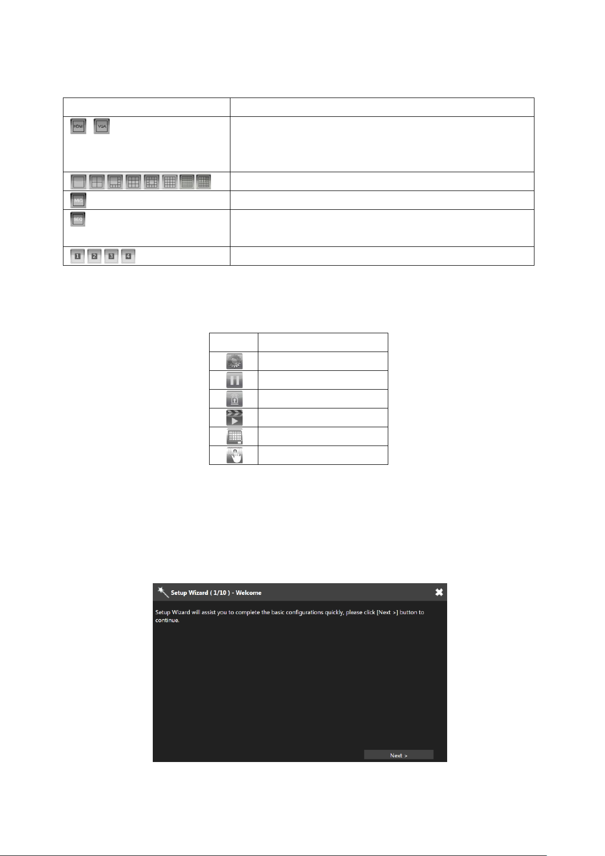
Chapter 4 Camera Setup
Click to enter NVR SETTINGS, and press CAMERA in the left pane to enter the
CAMERA SETUP page. The setting options are described below.
25 66-UM-NVR3-OOE-1
Page 26

Chapter 4-1 General
Camera Name: Enter the camera name to be displayed on the streaming screen.
Camera Source: Allocate a NVR channel for the camera.
IP Address: Enter the IP address of the camera you want to connect.
Dev. Info: Press to check ONVIF capability.
HTTP Port: Enter the port for HTTP connection.
RTSP Port: Enter the port for RTSP connection.
User: Enter the username required for camera authorization.
Password: Enter the password required for camera authorization.
Stream Type: Choose whether to stream only the primary video or dual (primary & secondary)
videos.
Primary Stream: Select the FPS and GOP for the primary stream.
Primary Stream Bitrate: Select the bitrate for the primary stream.
Secondary Stream: Select the FPS and GOP for the secondary stream (available only if Dual
Stream is activated in Stream Type).
Sec. Stream Bitrate: Select the bitrate for the secondary stream.
Decode Ref. : Select the number of reference frame for the decoder, and choose Immediate for
lower latency or Smooth for smoother but higher latency video.
Camera Disable: Disable the video function (live feeds and playback) of the selected camera.
Sync Time with NVR: Turn On for the camera to sync time with the NVR.
Assign RTSP URL: Assign required RTSP URL, NVR will connect to camera via required RTSP
URL but not Onvif.
RTSP Multicast Setting: Assign required RTSP multicast port.
WS Discovery: Click WS Discovery to scan for connected devices on the network. Click
Cancel to stop scanning.
Auto Adjust: Automatically assign IP for connected cameras.
Snap: Show snapshot thumbnails for all the cameras.
Set IP: Assign an IP address to the camera.
26 66-UM-NVR3-OOE-1
Page 27

Chapter 4-2 Video
In this page, you can adjust several camera parameters including Contrast, Brightness, Saturation,
and Sharpness.
Click Default to restore the NVR to its factory settings. Click Refresh to update the preview image.
Chapter 5 Record Setup
Click to enter NVR SETTINGS, press RECORD in the left pane to enter the
RECORD SETUP page. To adjust recording or schedule settings, the setting options are described
below.
Chapter 5-1 General
Record Mode: Switch on/off scheduled recording.
Audio: Switch on/off audio recording.
Post-alarm Record: Enable to record after an event takes place. Set the time (second) for the
NVR to record after the alarm is triggered.
Weighted Record: If any alarm is triggered when Weighted Record is turned on, the recording
frame rate will be adjusted to the pre-determined value (which can be set in CAMERA SETUP).
Otherwise, the NVR will record at a lower frame rate (approximately 4–5 FPS).
Note: System Recording Mode must set to Schedule and Recording schedule set to Always.
27 66-UM-NVR3-OOE-1
Page 28

Chapter 5-2 Schedule
To modify the recording schedule, switch the recording type from Always (continuous recording), Alarm
(record only when an alarm is triggered), or No Record (disable recording), and highlight the desired
date and time accordingly. Click Apply All to apply your selection of recording type to all dates and time.
Chapter 5-3 Advance
System Recording Mode: Choose between Manual or Scheduled recording.
Overwritten: Switch on to overwrite old files when the storage is full.
Pre-alarm Record: Switch on to start recording for a period before an alarm occurs.
Limited Recording: Set the number of days to record (from now to the designated day).
Protected Recording: Set how many days of video the NVR will preserve.
Chapter 6 Alarm Setup
Click to enter NVR SETTINGS, press ALARM in the left pane to enter the ALARM
SETUP page. The setting options are described below:
28 66-UM-NVR3-OOE-1
Page 29

Chapter 6-1 General
Alarm Input Type: Set the alarm sensor to Normally Open (NO), Normally Closed (NC), or IP
Camera. The last option will trigger the alarm only when receiving a signal from IP cameras.
Note: This information is available depending on models.
Motion Enable: Switch on/off motion detection. Remember also to set the motion detection area
in the tab MOTION AREA.
Motion Sensitivity: Adjust the sensitivity of motion detection. Higher sensitivity indicates that the
alarm can be more easily triggered.
Save Event Snapshot: Enable to store a snapshot on the hard drive when an alarm is triggered.
Chapter 6-2 Motion Area
Click and drag across the grid to highlight motion detection areas. Click Apply All Channels to apply
the areas to all camera channels.
Chapter 6-3 Output
Chapter 6-3-1 Alarm Led
Enable: Turn On to activate the alarm LED.
Alarm Time: Blinking duration of the alarm LED when an alarm is triggered.
Trigger Conditions: See Channel Events and System Events above for more details.
29 66-UM-NVR3-OOE-1
Page 30

Chapter 6-3-2 Buzzer
Enable: Turn On to activate the buzzer.
Alarm Time: Beeping duration of the buzzer when an alarm is triggered.
Note: SYSTEM SETUP > GENERAL > Buzzer must be enabled.
Trigger Conditions: See Channel Events and System Events above for more details.
Chapter 6-3-3 E-Mail
Enable: Turn On to activate e-mail sending.
Trigger Conditions: See Channel Events and System Events above for more details.
Alarm Send Interval: Set the frequency of sending alarm notification e-mail.
Chapter 6-3-4 FTP
Enable: Turn On to activate FTP sending.
Trigger Conditions: See Channel Events and System Events above for more details.
Alarm Send Interval: Set the frequency of sending image files to an FTP server when an alarm
is triggered.
30 66-UM-NVR3-OOE-1
Page 31

Chapter 6-3-5 Notification
Enable: Turn On to activate application notification sending.
Trigger Conditions: See Channel Events above for more details.
Chapter 6-3-6 DO#1–N (manual DO control)
Manual DO control: Turn On to enable directly DO control, in live video window will show the
corresponding DO number icon, click to control.
For other options, please refer to the descriptions above.
Chapter 7 Display Setup
DISPLAY provides several adjustable NVR parameters such as resolution, default number of
split views, and more other options. The details of these settings are described as follows:
Chapter 7-1 General
31 66-UM-NVR3-OOE-1
Page 32

Default Video Division: Select the number of split views you see when the NVR boots up.
HDMI Mode: Switch the output mode between DVI and HDMI.
HDMI Resolution: Select a screen resolution that fits your screen.
VGA Mode: Choose HDMI Sync to synchronize the videos for VGA and HDMI outputs. Choose
SPOT to display an HDMI/VGA switch button in the real-time view. Click the switch button to
switch control of split views between HDMI/VGA.
VGA Resolution: Select a screen resolution that fits your screen
Note: Availability depends on model.
Chapter 7-2 Advance
In this page, you can adjust brightness, contrast, saturation and hue of the NVR output. Click Load
Default to restore to the factory settings.
Note: Availability depends on model.
Chapter 7-3 Sequence
You are allowed to view videos of multiple cameras in sequence. Check the cameras you want to
monitor and choose the number of split views in the drop-down menu in Sequence Mode. Specify the
Sequence Interval for the NVR to switch to the next camera for monitoring.
32 66-UM-NVR3-OOE-1
Page 33

Chapter 8 PTZ Setup
Click to enter NVR SETTINGS, press PTZ in the left pane to enter the PTZ SETUP
page. The setting options are described below:
Chapter 8-1 General
Transfer Mode: Choose a PTZ communication protocol from HTTP, ONVIF, or Fish Eye.
Otherwise use RS-485.
RS-485 Protocol: Choose a RS-485 control protocol for your RS-485 PTZ device.
Note: Transfer Mode must be set to RS-485. Availability depends on models.
Control ID: Choose the corresponding device ID to control the camera.
Chapter 8-2 NVR Cascade
This tab allows you to cascade multiple NVRs or adjust relevant settings. For detailed instructions on
how to use the NVR cascade function, visit our official website. Enter Support > SDK, and download
the document named DVR/NVR IR/keyboard serial commands over HTTP. The settings listed in this
tab are described in details as follows:
33 66-UM-NVR3-OOE-1
Page 34

Show/Hide: Reveal or hide the password.
Modify: Apply the changes you've made.
Default: Restore to factory settings.
Search: Find all other NVR(s) connected to your network.
Export: Export the settings to the USB flash drive connected to the NVR.
Import: Load the settings from the USB flash drive connected to the NVR.
Chapter 9 Metadata Setup
Click to enter NVR SETTINGS, and press METADATA in the left pane to enter the
METADATA SETUP page. The setting options are described below:
Chapter 9-1 General
The NVR supports various external devices such as GPS or POS, and in this page you are allowed the
change the settings for these devices. The setting options are described as follows:
Serial Input: Select the USB port to which your external device is connected.
Metadata Service: Turn On to enable using external devices.
Serial Device Server: Enter the server IP for your serial device.
34 66-UM-NVR3-OOE-1
Page 35

Server Data Port: Enter the port of your serial device.
Server Command Port: Enter the command port of the device.
Emulated Mode: Choose an emulation type from the drop-down menu (see image below).
Encoding Mode: Choose between ASCII and UTF-8.
Baud Rate: Select an option suitable for your device.
Data Size: Select an option suitable for your device.
Parity: Select an option suitable for your device.
Stop Bit: Select an option suitable for your device.
Flow Control: Select an option suitable for your device.
OSD Font Color: Choose a color for the OSD font from the spectrum (see image below).
OSD Font Size: Enter a value as the font size.
OSD Rows Displayed: Determine the number of rows for the OSD.
Chapter 9-2 Event
This tab displays a history of received metadata. You are allowed to search for events based on time,
channel, or content.
Chapter 10 Other Setup
Click to enter NVR SETTINGS, and press OTHER in the left pane to enter the
OTHER SETUP page. The setting options are described below:
35 66-UM-NVR3-OOE-1
Page 36

Chapter 10-1 Smartphone
This tab provides settings for sending alarm notifications to your smartphone that is paired with the NVR.
You can download IPCamPlus in App Store or Google Play for your iPhone, iPad, and other Android
devices.
Trigger Conditions: See Channel Events above for more details.
Push Device List: Click Show to open a dialog, display all registered mobile devices that
required push notification.
Chapter 10-2 IVS
The NVR supports IVS-enabled cameras. Connect an IVS-enabled IP camera to the NVR and turn on
the IVS function. Go to ALARM SETUP > GENERAL > Alarm Input Type > IP Camera, and the NVR
will receive and record IVS information in the history table.
Chapter 11 Stream
Once the network configurations are completed and cameras connected, you can remotely view live
streams of cameras via an Internet browser, and access other functions such as playing recorded video
and backing up video files.
Note: IE 10 or above, or Chrome are recommended
Enter the NVR IP address or domain name in the address bar:
Enter the NVR username and password required for login authorization
36 66-UM-NVR3-OOE-1
Page 37

Then log into the STREAM menu.
Note: NVR remote access requires corresponding access privileges.
Chapter 11-1 Live
The LIVE tab displays the streams of all connected cameras. With the control buttons and joystick you
can control the movement of the selected camera.
Chapter 11-2 Play
In PLAYBACK, you can view recorded videos according to date/time, alarm/manual history table, and
37 66-UM-NVR3-OOE-1
Page 38

timeline.
Chapter 11-3 Backup
In BACKUP, you could back up recorded videos by choosing the date/time, channel, and file format.
Click Backup to start the backup process.
38 66-UM-NVR3-OOE-1
Page 39

Appendix
Install IPCamPlus
Search and download IPCamPlus in the iOS App Store or Android Play Store. Or you can scan the QR
code below:
For Android Users
Open IPCamPlus, and go to tab Grouping.
Tap a group, and tap the camera filed to add an NVR.
Next, enter the required NVR information, and then tap Done to save. Tap Live to monitor the NVR.
39 66-UM-NVR3-OOE-1
Page 40

For iOS User
Open IPCamPlus, and then tab Grouping.
Tap a group, and tap the camera filed to add an NVR.
Next, enter the required NVR information, and then tap Done to save. Tap Live to monitor the NVR.
40 66-UM-NVR3-OOE-1
 Loading...