

Page 1
Touch Screen Keypad
USER'S MANUAL
for Navigator Touch Screen Keypads
D8x/D16x Deluxe
Hardware & Firmware v8.0
Document 890-020
Rev 1.1
Page 2

Innovative Electronic Solutions
www.ness.com.au
National Customer Service Centre
Ph: 1300 551 991
customerservice@ness.com.au
D8X/D16X DELUXE
USER'S MANUAL FOR NAVIGATOR KEYPADS
Document Part No: 890-020
Rev 1.1 Mar 2019
For use with Ness D8x/D16x DELUXE control panels V8.0 and later.
This manual can also be used for previous versions of D8x/D16x panels however
some of the programming options covered are available only in V8.0 and later.
Refer to user manual 890-016 for LCD keypad operation
WARNINGS & NOTICES
Ness Corporation manufacturing processes are accredited to ISO9001 quality standards and all possible care and
diligence has been applied during manufacture to ensure the reliable operation of this product. However there are
various external factors that may impede or restrict the operation of this product in accordance with the product’s
specification.
These factors include, but are not limited to:
1. Erratic or reduced radio range (if radio accessories are installed). Ness radio products are sophisticated low
power devices, however the presence of in-band radio signals, high power transmissions or interference caused
by electrical appliances such as Mains Inverters, Wireless Routers, Cordless Phones, Computers, TVs and other
electronic devices may reduce radio range performance. While such occurrences are unusual, they are possible.
In this case it may be necessary to either increase the physical separation between the Ness receiver and other
devices or if possible change the radio frequency or channel of the other devices.
2. Unauthorised tampering, physical damage, electrical interruptions such as mains failure, electrical spikes or
lightning.
3. Solar power inverters are a known source of electrical interference. Please ensure that this product and all
associated cabling is installed at least 3 metres away from a solar power inverter and its cabling.
WARNING: Installation and maintenance to be performed only by qualified service personnel.
CAUTION: Risk of explosion if battery is replaced by an incorrect type. Dispose of used batteries in accordance
with local regulations.
ADSL NOTICE: ADSL broadband data can interfere with the operation of your alarm dialler. It is recommended that
a quality ADSL filter be installed as per the filter manufacturer's guidelines in premises with an alarm dialler installed.
COPYRIGHT NOTICE
All rights reserved. No part of this publication may be reproduced, transmitted or stored in a retrieval system in any form or by any
means, electronic, mechanical, photocopying, recording, or otherwise, without the prior written permission of Ness.
Ness reserves the right to make changes to features and specifications at any time without prior notification in the interest of
ongoing product development and improvement.
© 2019 Ness Corporation Pty Ltd ABN 28 069 984 372
Page 3

Contents
Introduction ......................................................4
Navigator System overview .........................................5
Navigator Touch Screen Keypad overview ..............................6
Information Screen ................................................7
Care & Cleaning ..................................................8
Applying the Protective Film .........................................9
Zone Status Display ..............................................10
Clock Display ...................................................11
System Alarm Displays .........................................12, 13
Arming the System ...............................................14
Disarming the System .............................................15
Home Mode ....................................................16
Duress Alarm ....................................................17
Emergency Alarms ...............................................18
Excluding Zones .................................................19
Event Memory ...................................................20
Day Mode Setup .................................................21
Day Mode Operation ..............................................22
Auto Time Automation ............................................23
Auxiliary Outputs, Manual Operation .................................24
Programming ...................................................25
How to enter program mode ......................................26
Set Brightness, Set Volume .......................................27
Edit Zone Names, Edit AUX Output Names ..........................28
Zone Name Library .............................................29
Setting the Real Time Clock ......................................30
User Codes Options Table .......................................31
User Codes Programming .......................................32
Radio Keys Programming ........................................33
Timer Programming, Entry/Exit Delays ..............................34
Follow Me Telephone Number Programming .........................35
Monitoring Operation .............................................36
Remote Operation by Telephone ................................. 37,38
Troubleshooting .................................................39
Installation Record ...............................................40
Page 4
Introduction
The Ness Navigator is a revolutionary
touch screen interface for use with the
Ness D8x/D16x1 series alarm control
panels.
Navigator has a large touch sensitive
3.5” colour LCD which is easy to read,
easy to use and makes operating your
Ness alarm system a real pleasure.
The large colour screen means Navigator can tell you much more than a
conventional keypad can.
Zone descriptions are displayed in plain
English and you can even edit zone
names yourself to reflect the names of
rooms in your own premises.
Not only does Navigator provide valuable information about your Ness alarm
system, it allows you to arm and disarm
your system, tells you what the system
is doing, you can use it to program
alarm system and if that’s not enough Navigator just looks great!
1
Navigator Touch Screen Keypad is compatible with Ness D8x and D16x control panels Version 7 and later.
4
Page 5
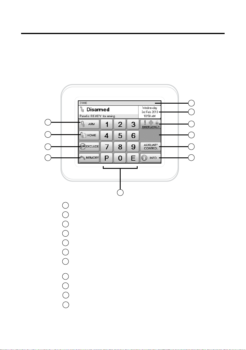
Your Navigator System
Your Ness Alarm System
Ness Navigator Touch Screen Keypad is the face of your Ness D8x or D16x
Navigator Alarm System.
Navigator’s self-explanatory operation guides provide you with plain English
displays and intuitive touch screen operation.
The interactive display screens make it easy to view all your zones with your
own text descriptions, get help and prompts for arming, disarming, operating
outputs, emergency alarms and more.
TOUCH
SCREEN
KEYPAD
TOUCH
SCREEN
KEYPAD
TOUCH
SCREEN
KEYPAD
TOUCH
SCREEN
KEYPAD
8 or 16 Zones for PIRs, Door & Window Switches, Vibration Sensors, Smoke Detectors...
OPTIONAL Card/Fob Reader
OPTIONAL RADIO DEVICES
Radio keys, PIRs, Radio Reed Switches,
Radio Keypad, Radio Smoke Detector...
MAIN
HOUSING
Internal Sire
External Siren
Strobe Light
Auxiliary Outputs for optional connection
to Electric Roller Doors, Lighting, Line Fail
Output, Radio Key Panic Output, Radio Key
RKP
RADIOKEYPAD
AUX Output and more...
Power supply (Supplied)
n
Up to four Navigator
Touch Screen Keypads
per system.
Telephone Dialler Built-in
Telephone Lead (Supplied)
5
Page 6
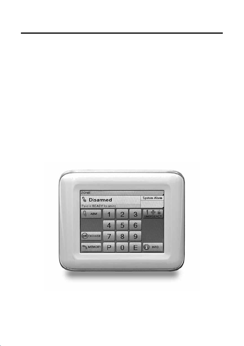
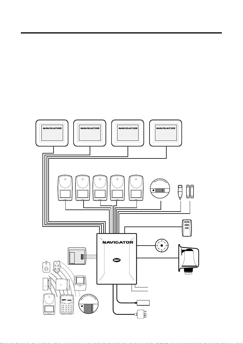
Overview
The Disarmed Screen
In the normal disarmed mode, the Navigator screen displays information
about the state of your system and gives you instant access to commonly
used functions.
6
7
1
2
3
4
5
Touch to arm the system. Page 14.
1
Touch to arm Home Mode. Page 16.
2
Touch to Exclude zones. Page 19.
3
Touch to view the event memory. Page 20.
4
Numeric keypad.
5
Touch to view the full zone list. Page 10.
6
Touch here to view the calendar. Page 11.
7
This area also displays System Alarms. Page 12.
Touch to activate the Emergency Alarms. Page 18.
8
This area displays current Emergency Alarms.
9
10
Touch to control the Auxiliary Outputs. Page 24.
11
Touch to display the information screens. Page 7.
8
9
10
11
6
Page 7
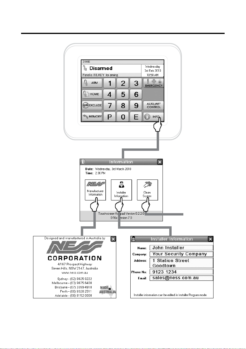
Info Screen
Ness Corporation contact details.
See page 8.
Your installer’s contact details are stored
here. Never lose a business card again!
7
Page 8
Care & Cleaning
Caring for your Navigator
Do not use a pen, screwdriver or other sharp implement to press the touch
screen. Permanent damage may result and will invalidate any warranties.
Please press lightly, the touch screen does not need heavy force to operate.
Pressing too hard may damage the LCD screen and the housing. Navigator
responds to every touch with a short beep.
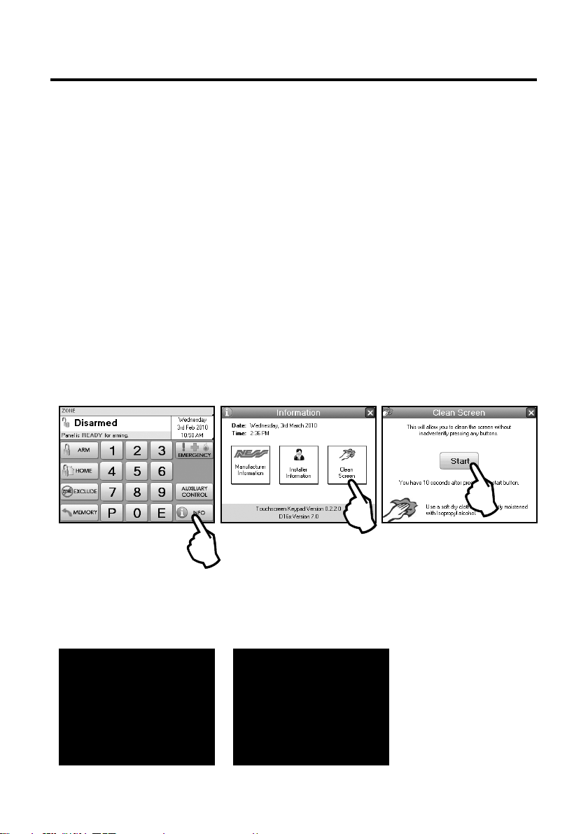
Cleaning The Touch Screen
Do not clean the touch screen with abrasive cleaners. Navigator’s Clean
Screen page. While the system is disarmed, press Info, Clean Screen to see
the cleaning instructions.
STEP 1. In the disarmed
mode, press Info.
Step 4. The touch screen will be disabled for 10 seconds. Clean
the bare screen or the protective film using a soft dry cloth or a
cloth moistened with Isopropyl Alcohol.
Avoid chemical cleaners and solvents which may damage plastic
components.
You have 10 seconds left.
STEP 2. Press Clean Screen. STEP 3. Press Start.
Screen cleaning time
has finished.
8
Page 9
Screen Protection
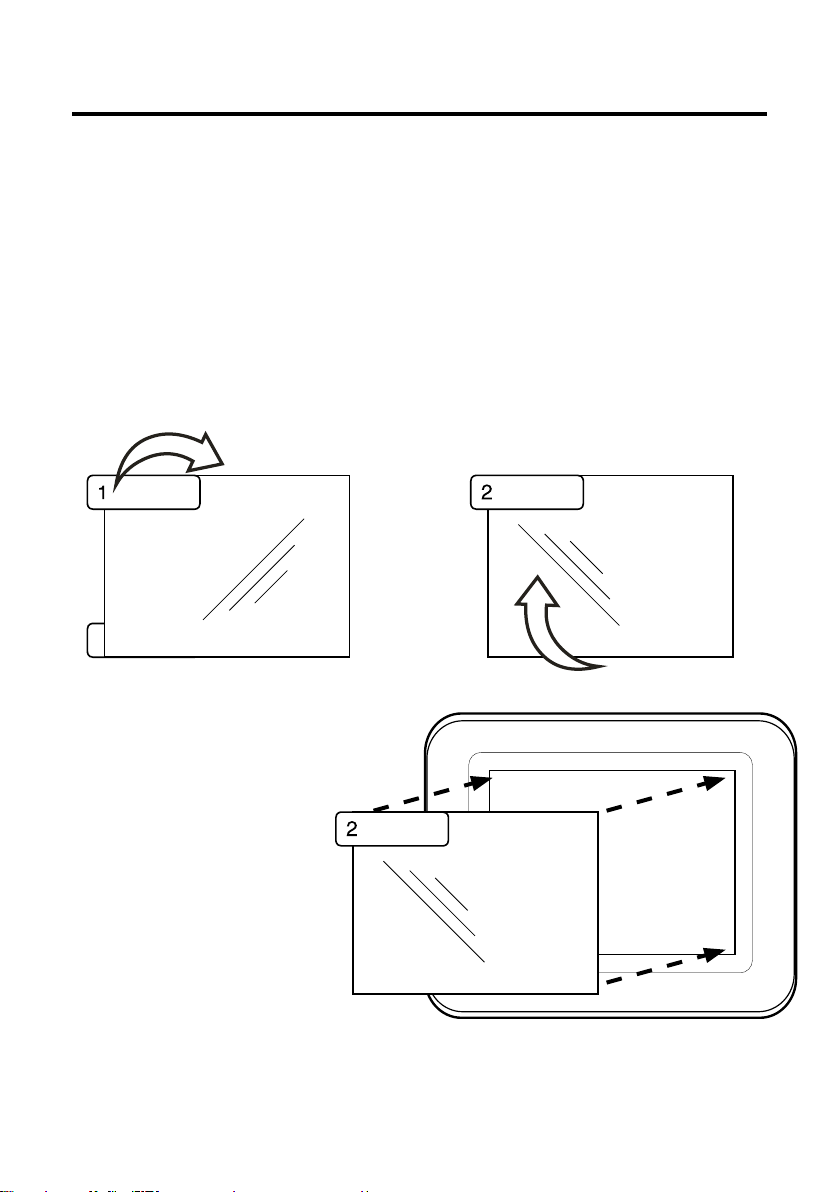
Applying the Protective Film
Navigator Touch Screen Keypad is supplied with a self-adhesive screen protector
to help protect the sensitive touch surface from marks and scratches which may
appear under normal use.
We highly recommend that you apply the protective film to keep the touch surface
looking brand new for years to come.
STEP 1. Use the orange No. 1 tab to
peel off the self-adhesive backing.
Please peel off this
mask BEFORE application
STEP 3. Holding the
protective film by the green
tab, carefully apply the film
to the Navigator’s screen.
Start applying at one end and
smooth the film as you go to
remove any air bubbles
STEP 4. Use the green tab
to peel off and discard the
topmost layer of the film.
Your Navigator is now ready
for use.
Please peel off this mask
AFTER application completed
STEP 2. Flip the film over to position
the green No. 2 tab at the top left.
Please peel off this mask
AFTER application completed
9
Page 10
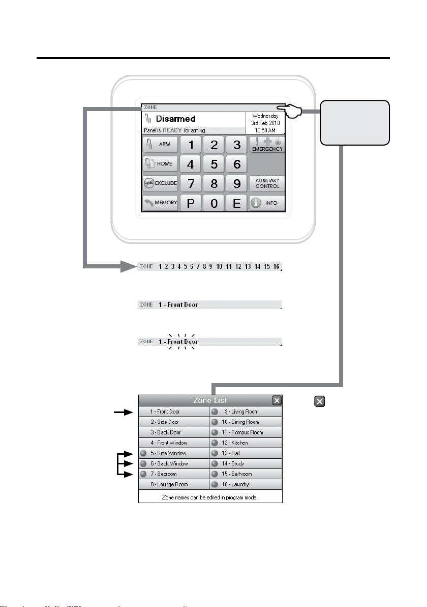
Zone Status Display
The Zone Status Bar displays the zone numbers
of unsealed zones.
If only one zone is unsealed its description will
also be displayed.
Touch the Zone
Status Bar to
display the full
zone list.
The zone number and
description of all zones.
Unsealed zones
show a red indicator.
Zones which are currently in the alarmed state are
displayed in flashing red text.
Touch to close the window.
The Zone List display will show
8 or 16 zones depending on
whether your Navigator Control
Panel is a D8x or D16x.
Zone names can be customised in
program mode. Page 28.
10
Page 11
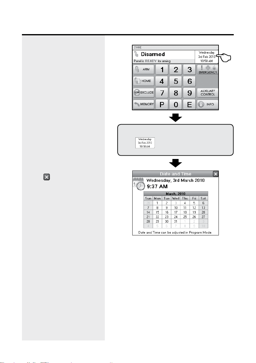
Clock Display
The date and time are normally
displayed when the system is
armed or disarmed.
The date and time can be set in
User Program Mode, see page 30.
If there is a System Alarm, this area
will display the alarm. See next
page.
To display the full calendar.
Touch to close the window.
Touch
11
Page 12
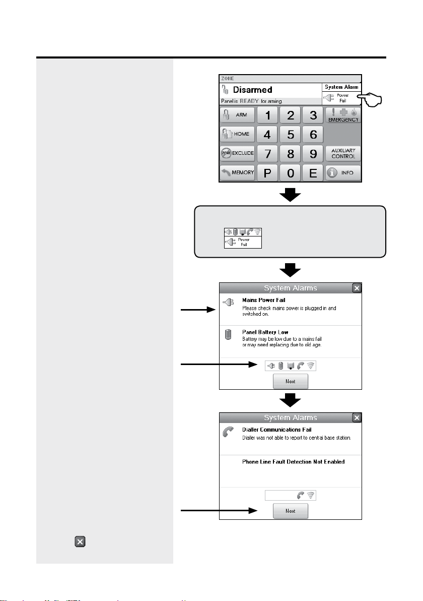
System Alarm Display
If there is a System Alarm, the
clock area will display the alarm.
Touch to display details.
To display System Alarm details.
Full description of the System
Alarm and what action to take.
Outstanding System Alarms
shown here.
Dialler Communication Fail means
your dialler was not able to send
an alarm message. This message
is usually seen if the panel has
not been acknowledged remotely
when using Audible Monitoring.
See page 36.
Touch Next to view any other
System Alarms.
Touch
the system alarm area.
Touch to close the window.
12
Page 13

System Alarm Display
Radio Key low battery alarm.
Radio Tamper alarm indicates that
a device such as a Radio Reed
Switch or the R12 Radio PIR may
have been opened. Check the
device.
Radio Supervision, if enabled by
your installer, alerts you if a radio
device has not transmitted a signal
for a set interval. Ask your installer
to check the radio device.
External Tamper alarm and Panel
Tamper alarms. Check the external
siren cover and main panel.
Touch to close the window.
13
Page 14

To Arm
10
The control panel must be armed
in order to detect intruders.
Before arming, make sure all zones
are “sealed” by ensuring there is
no movement in rooms covered by
motion detectors and that doors
or windows protected by reed
switches are closed. The display
will tell you when the system is
ready for arming.
SIREN WARNING
At the end of the exit time, all
zones should be sealed. If any are
unsealed, the siren will sound for
2 seconds to indicate that those
zones have been automatically
excluded. You should disarm
the panel, check the premises
and then arm again. Continual
warnings could mean there is a
problem with a detection device you will have to manually exclude
the zone before attempting to arm
the system.
If a zone is unsealed at the end
of exit time and the auto-exclude
option is disabled, the siren will
sound for the duration of siren
time, (the default is 5 minutes).
To arm the system.
Touch
or touch
+
+ +
A valid user code.
means mains power may be turned
10 beeps on arming
off or the backup battery is low.
One long beep when
you arm could mean the panel is
already armed or the keypad code
is wrong, (if not using Shortcut
Arming).
14
Page 15

To Disarm
When you enter the protected
premises through a delay zone,
the keypad responds with regular
beeps1 as a reminder to disarm.
If the panel is not disarmed by the
end of the entry delay time, an
alarm will occur.
Using the optional radio keys,
you may disarm your system from
inside your premises or from just
2
outside.
If you make a mistake when
entering your user code, press”E”
and start again. Five incorrect
entries will cause an alarm.
The panel can be reset and the
siren/s silenced by disarming the
panel.
If you arrive at your premises and
find the strobe light flashing
the panel as above. To check the
cause of the alarm, you can view
the alarms in memory by entering
Memory Mode.
3
reset
To disarm the system.
Touch
A valid user code.
+
ARM ONLY CODES
User codes can optionally be
programmed to be Arm Only
codes. An Arm Only code can arm
the system but it cannot disarm.
However if an Arm Only code is
assigned to a radio key, the radio
key OFF button will arm and
disarm.
1
If Entry Beeps are enabled.
2
The strobe light will flash to
indicate arming and disarming by
radio key. Your installer can also
enable siren ‘Chirps’ for an audible
indication of radio key operation.
3
In the event of an alarm, the
strobe light will flash for 72 hours or
until the panel is reset.
AUTO RE-ARM
Your panel may be programmed for Auto ReArm to help prevent accidental disarming.
Auto Re-Arm checks that you have entered the
premises after disarming. If all zones remain
sealed for a period as set by the entry delay
time then the panel will re-arm. This is most
useful when used with radio keys where the
OFF button might be accidentally pressed after
you have armed and are leaving the premises.
15
Page 16

To Arm Home Mode
Home mode allows you to arm
selected zones while others are
ignored. Typically, perimeter zones
(doors and windows) can be
monitored while you are at home.
Your installer must program which
zones will be active in Home mode.
If an alarm occurs while in Home
mode, entering a valid user code
+ E will silence the alarm. This
will also disarm the panel, so
remember to re-arm Home mode
again if needed.
Using the optional Radio Keys you
can arm Home Mode by pressing
either the OFF button or the ON
button twice within 4 seconds or
by pressing the AUX button, (RK4
radio key only). These options
must be enabled by your installer.
Note: Home Mode and Area arming
Home Mode can be used if the
panel is fully disarmed or if only
Area2 is armed. Home Mode is not
available when Area 1 is armed.
The panel can be armed in Home
mode if Area2 is already armed on
these conditions:
• Area 1 must be OFF.
• Area 2 must be armed first, and
then Home Mode armed – not the
reverse.
• Zones assigned to both Home
mode and to Area 2 will act as
Home Mode zones when both
Area 2 and Home Mode are armed.
Note: Home Mode arming when
Area2 is armed cannot be done by
Radio Key or by keyswitch.
Touch
or touch
NOTE
In normal disarmed mode, the Home Mode
button
has enabled Home Mode.
+
+ +
A valid user code.
is visible only if your installer
16
Page 17

Keypad Duress Alarm
The DURESS alarm can be used
to send a silent alarm to the central
station that you are being forced to
disarm the panel against your will.
That is - you are disarming under
“duress.”
To disarm and send a DURESS
alarm, prefix your User Code with
one of the digits 5, 6, 8 or 9 when
disarming.
* The Keypad DURESS is normally
not enabled. To enable this
function, consult your installer.
* DURESS alarms can only used
by systems which are monitored by
a Central Station.
* The DURESS alarm can be
programmed to sound the internal
siren (Reset output). This option is
Off by default.
To trigger the keypad Duress Alarm, add a
special digit before your user code when
disarming.
Touch
Your system will now be disarmed and
a silent Duress alarm is sent to your
central monitoring station.
+ +
A valid user code.
You can precede your user
code with any of the digits
5, 6, 8 or 9.
17
Page 18

Emergency Alarms
PANIC ALARM
The Panic alarm may have been
programmed to be either Audible
to activate the sirens, or Silent to
send a PANIC report by dialler if
your system is monitored by a
Central Station.
The Emergency Alarm display will
show Medical and Fire alarms only
if they have been enabled by your
installer.
The Medical alarm sends a medical
alarm report by dialler if this option
has been enabled by your installer
and the system is monitored by a
central station.
The Medical Alarm does not sound
the sirens.
The Fire alarm sounds the siren
using the Fire Alarm sound and
sends a Fire Alarm report by dialler.
If this option has been enabled by
your installer and the system is
monitored by a central station.
To trigger Emergency alarms.
Touch
If the Panic Alarm Shortcut is not enabled,
you are required to enter your user code
+ E to trigger the panic alarm.
Touch
to close the window.
18
Page 19

Excluding Zones
If there is a problem with a
detection device and the zone
cannot be sealed when arming
the panel, then that zone can be
manually Excluded so that it does
not generate alarms.
When zones have been Excluded,
the EXCLUDE light flashes
continuously while the panel is
disarmed and also when armed.
Zones can be excluded while the
panel is either disarmed or armed.
See notes below.
Zone Exclude is not permanent.
Excluded zones are automatically
included next time the panel is
disarmed.
To Exclude zones.
Touch
Then touch the zone name/s to toggle the
exclude status for one or more zones.
Excluded zones are indicated by the
Touch
to close the window.
icon.
In both disarmed and armed
modes, the Zones Excluded icon
flashes to indicate that there are
zone/s excluded.
Flashing
Flashing
19
Page 20

Event Memory
The panel stores a comprehensive
event memory, including Arming,
Disarming, Low Battery, Mains Fail
and Alarm events.
The memory is constantly
upgraded and the last 80 events
with time & date are always
available for viewing.
This memory display can only be
selected while the panel is in the
disarmed state.
The MEMORY button flashes
continuously when an alarm has
occurred as a reminder to view the
alarm memory.
Touching the MEMORY button to
view the event history also clears
the flashing memory alert.
The Event Memory window will
close automatically when the last
event has been viewed.
Touch
to close the window.
To view the Event memory.
Touch
Press Next to view the event memory from
most recent to oldest.
There is no need to refer to charts or tables
- the event memory describes exactly what
you’re viewing, in plain English.
20
Page 21

Day Mode - Set up
Your Navigator control panel has a
Temporary Day Zone feature which
allows easy and flexible Day Zone
selection and operation.
Temporary Day Zones operate in
addition to Permanent Day Zones
which are usually set up by your
installer.
You can easily enable and disable
Temporary Day Zones and even
program which zones will be Day
Zones from the Navigator Touch
Screen keypad.
Day Zones can be programmed by
your installer to beep the keypad,
or briefly sound the siren/s or flash
the strobe light, or to sound an
optional buzzer.
TYPICAL APPLICATIONS
Day Zones are useful for a variety
of applications such as a shop
door beeper triggered by a reed
switch on the door.
For example, in a shop situation
you can use Day Mode to alert you
when a customer enters the front
door.
You can also use Temporary Day
Zones to monitor switches on, for
example, the rear door or the fridge
doors.
Select which zones will be Temporary Day
Zones. You probably will only need to do this
once or occasionally.
To enter Temporary Day Zones selection.
Touch
Then touch the zone name/s you want to
enable or disable as Day Zones.
Selected zones are indicated by the
+
icon.
Note for installers and advanced
users: Permanent Day Zones are
not displayed in selection mode.
Permanent Day Zones can be
selected as Temporary Day Zones
but this has no effect as those
zones are already day zones.
Touch to close the window.
21
Page 22

Day Mode - Operation
This enables/disables both
Temporary and Permanent Day
Zones.
When Day Mode is enabled, any
unsealed day zone will sound the
programmed output for 2 seconds.
When Day Mode is disabled, an
unsealed day zone will simply be
indicated on the keypad as an
unsealed zone.
Day Mode can be enabled when the panel is in
the normal disarmed mode.
To enable Day Mode.
Touch
To disable Day Mode.
Touch
+
+
22
Page 23

Auto Time
HOME
ARMED
ARMED
Auto Time - automating your
Navigator security system.
Your D8x/D16x Navigator panel
features sophisticated automation
features making full use of the
onboard Real Time Clock and a set
of powerful yet simple to program
options.
AUTO TIME WARNING PERIOD
(Optional function - must be enabled by your installer.)
When an Auto Time event is about to begin, your keypad (or keypads) will begin a constant
slow beep as a warning that the automatic event is about to happen. The warning beeps can be
programmed to start up to 99 minutes prior to the AutoTime event.
Press any key on the keypad to stop the beeps during the warning period. The beeps will start
again for the final minute at a faster rate.
Final Minute beeps. In the last minute prior to the Auto Time event, the keypad will beep at a
faster rate to warn that the event is about to start.
ARM or DISARM AUTOMATICALLY at
pre-programmed times of day or day of
the week.
Increase site security. No need to rely on
staff remembering to arm or disarm the
system.
TURN AUX OUTPUTS ON or OFF at
pre-programmed times - every day,
once a week, any time. Automate doors,
sprinkler systems, lights and more.
ENABLE/DISABLE USER CODES
depending on the time of day or day of
the week. Allows managers to grant users
access to the system at selected times
and deny after hours entry.
TO DELAY THE AUTO TIME EVENT
(Optional function - must be enabled by your installer.)
To delay the Auto Time event, enter a valid user code on its own. (The user code must be assigned
to an Area to work). This will suspend the warning beeps and the AutoTime event for 1 hour - when
the warning process will start again.
Example: Your panel is programmed to Auto Arm at 6pm every weekday and the Warning Period
is programmed for 5 minutes. You are working back late and at 5:55pm your keypad begins to
beep. Since you're not ready to arm the system yet, enter your user code (without pressing E) at
the keypad. The warning beeps will stop and arming will be delayed by one hour. At 6:55pm the
warning beeps will start again, followed by automatic arming if you don't delay the event again.
Any AutoTime event can be postponed, not just arming. You can also delay the automatic turn (or
off) of one of the AUX outputs in the same manner.
23
Page 24

AUX Outputs - Manual Operation
Manual Operation Of the Aux
Outputs (Optional function - must
be enabled by your installer.)
As well as automatic operation by
Auto Time, the auxiliary outputs
can also be operated manually by
keypad.
The Auxiliary Output Control screen
shows the AUX outputs which have
been programmed for keypad
control by your installer.
Touch a button to Pulse on or
toggle an output. (Pulse or toggle
is programmed by your installer.)
Note. Your panel has 4 x Auxiliary
outputs onboard. Auxiliary
outputs 5 to 8 are optional
depending on availability of the
output expander accessory.
To operate the AUX outputs.
Touch
Auxiliary Control is available in all modes,
including when the system is armed.
MANUAL OPERATION AND AUTO TIME
SCHEDULES
Manual operation of outputs works in
conjunction with AutoTime schedules, if
programmed.
For example, if AutoTime has turned an output
on as scheduled (say, a light) you can manually
turn it off (and back on again) any time you
wish. At the scheduled turn OFF time, if the
output is still on it will be turned off.
24
Page 25

Programming
How to enter program mode .......................................26
Set Brightness, Set Volume ........................................27
Edit Zone Names, Edit AUX Output Names ............................28
Zone Name Library ...............................................29
Setting the Real Time Clock ........................................30
User Codes Options Table .........................................31
User Codes Programming .........................................32
Radio Keys Programming ..........................................33
Timer Programming, Entry/Exit Delays ...............................34
Follow Me Telephone Number Programming ..........................35
25
Page 26

Programming - How to enter Program Mode
In User Program Mode you can
program User Codes, Timers, Real
Time Clock, Follow Me Telephone
Number.
USER CODES
The panel has 56 user codes which
can be operated by keypad code
(3-6 digit PIN), by optional radio
key or by optional access cards.
The factory default Master Code
is 123. You should re-program
this code with a new code of your
own choice.
TIMERS
You can also re-program the Entry
Delay Time and Exit Delay Time if
you need more or less time to exit
and enter the premises.
REAL TIME CLOCK
Some automation features such as
AutoTime rely on the onboard Real
Time Clock. Set the current date
and time to ensure events take
place as expected.
You will need to adjust the Hours
setting when Daylight Savings
starts and ends.
Enter program mode when the panel is in the
normal disarmed mode.
To enter User Program Mode.
Touch
To exit User Program Mode.
Touch
The panel will automatically exit Program Mode
if the keypad is inactive for 4 minutes.
+ +
Your Master code.
+
FOLLOW ME TELEPHONE NUMBER
If your panel is set up for Audible
Voice monitoring, you can program
the Follow Me Telephone Number
to temporarily replace the two
installer-programmed phone
numbers.
26
Page 27

Programming - Navigator Configuration
The Navigator Configuration screen
allows you to:
SET BRIGHTNESS
Adjust the brightness of the
Navigator’s LCD screen backlighting to suit the room.
SET VOLUME
Adjust the beep volume of the
Navigator touch screen.
DEFAULT ALL CONFIG ITEMS
This option deletes your
custom settings and returns all
configuration options to factory
default settings.
In User Program Mode.
Touch
Slide your finger along the Brightness
slider to adjust the brightness from 1%
to 100%
Slide your finger along the Volume slider
to adjust the touch screen beep volume
from 1% to 100%. The volume cannot be
set to zero.
27
Page 28

Programming - Navigator Configuration
EDIT ZONE NAMES
Edit the zone names to suit your
own premises. For example,
instead than meaningless
numbers, zones can be given
names that mean something to
you, such as Front Door, Back
Door, Lounge Room, etc.
You can choose from a library
of common zone names or type
your own names using the on
screen QWERTY keyboard.
EDIT AUX OUTPUT NAMES
If your installer has installed
automation options, you can edit
the names of the auxiliary outputs.
The example opposite shows
how to edit Zone Names. Follow
the same procedure to edit Aux
Output Names.
Touch a zone name. If you have a
Navigator D8x panel this display will
show 8 zones.
Next/Previous zone
Backspace
Move cursor Left/Right
Opens zone name library
To return to the zone list
Edit the name of the zone.
28
Page 29

Programming - Navigator Configuration
EDITING ZONE NAMES
Using the Zone Name Library.
Touch a zone name to display the zone
name editor.
Next/Previous zone
Backspace
Move cursor Left/Right
Opens zone name library
To return to the zone list
Touch Select to open the
zone name library.
THE ZONE NAME LIBRARY.
You can use the zone name editor
to type the names of all your
zones.
To save you time, Navigator Touch
keypad has a built-in library of
common zone names. You can
even choose a zone name from
the library and add more text to
customise it further.
For example. Choose “Garage”
from the library and add “Roller
Door” or “Detector” or “Window”.
Choose a pre-defined zone name from
the library then press
library.
to close the
29
Page 30

Programming the Real Time Clock
This option allows you to program:
DAY OF MONTH (01-31)
MONTH (01-12)
YEAR (10-63)
HOUR (00-23) 24hr time format
MINUTE (00-59)
The Day Of Week does not need to
be programmed. It is automatically
calculated from the date.
DATE FORMAT
The date is entered in 24 hour format
but is displayed on screen in 12 hour
format.
In User Program Mode.
Touch
To program.
Touch
Touch
Touch
Touch
+ +
+ +
+ +
+ +
01-31
01-12
10-63
00-23
Touch
EXAMPLE: To set the Day Of Month.
Touch
Enter Day of Month (01-31) +
The green status bar will show the new
setting.
00-59
+ +
30
Page 31

Programming User Codes
USER CODE PROGRAMMING RULES
• Up to 56 Keypad Codes can be used
at up to 4 wired Navigator keypads for
controlling all panel functions including
Arming & Disarming, Home Mode, Panic,
memory recall and much more.
• Keypad Codes (or PINs) can be 3 to 6
digits in length and can be individually
programmed and deleted.
USER CODE OPTION NO. PIN
1 (Master Code) P201E 123
2 P202E
3 P203E
4 P204E
5 P205E
6 P206E
7 P207E
8 P208E
9 P209E
10 P210E
11 P211E
12 P212E
13 P213E
14 P214E
15 P215E
16 P216E
17 P217E
18 P218E
19 P219E
20 P220E
21 P221E
22 P222E
23 P223E
24 P224E
25 P225E
26 P226E
27 P227E
28 P228E
• User Code 1 is also the Master Code
which is used to enter User Program
mode.
• User Codes 2 to 56 can be programmed
to be Radio Codes or Access Cards as
required. Ask your installer.
USER CODE OPTION NO. PIN
29 P229E
30 P230E
31 P231E
32 P232E
33 P233E
34 P234E
35 P235E
36 P236E
37 P237E
38 P238E
39 P239E
40 P240E
41 P241E
42 P242E
43 P243E
44 P244E
45 P245E
46 P246E
47 P247E
48 P248E
49 P249E
50 P250E
51 P251E
52 P252E
53 P253E
54 P254E
55 P255E
56 P256E
31
Page 32

Programming User Codes
In User Program Mode.
Refer to the User Code options table on page
31 then enter the option number of the user
code you want to program.
The option number
and the current user code
is displayed.
Note 1. User codes must NOT
start with zero. (The panel will
allow codes beginning with zero
to be programmed but they will
not operate the panel. This is an
alternative method for disabling
user codes.)
Note 2. All codes must be unique
to each other. Codes are rejected
if already used. Some codes that
are similar to existing codes may
also be rejected.
Touch
Now enter your new user code (PIN). The
code can be 3 to 6 digits in length.
Touch
Then enter the PIN again to confirm.
Touch
+ +
3 digit option
number
Your new PIN
Your new PIN
+
+
Touch to delete a user code.
The new user code will be displayed.
ARM ONLY CODES
If a code has been programmed
by your installer to be an Arm
Only code, then that user code can arm but not
disarm the panel. This is handy for cleaners,
temporary staff etc.
32
Page 33

Programming Radio Keys
Each of the User Codes, except
for the Master Code, can be
programmed to be Radio Codes.
This allows up to 55 Ness Radio
Keys to be used for arming and
disarming of the panel.
The optional Ness Radio Interface
is required for radio operation. Ask
your installer.
Indicates that this code has been
enabled as a Radio Code.
If the option has been enabled by
your installer.
Touch to delete a Radio Key.
In User Program Mode.
Refer to the User Code options table on page
31 then enter the option number of the user
code you want to program.
Touch
Touch
The display will show
+ +
3 digit option number
Example, P203E
The green status bar will
indicate that the Radio Key was
successfully programmed.
If you hear a long beep, the Radio
key may already be programmed
at another user code.
Press the disarm button on
your Ness Radio Key
(or the No. 1 button).
33
Page 34

Programming Timers
This option allows you to program:
ENTRY DELAY TIME 1 (01-99 sec)
Entry Delay Time 1 sets the time
allowed to enter the premises
through a delay zone.
ENTRY DELAY TIME 2 (01-990 sec)
If enabled by your installer, this
timer is used to give extra long
entry delay on selected zones.
Entry Delay Time 2 is internally
multiplied by 10. For example,
enter 12 to get a time of 120
seconds.
EXIT DELAY TIME (01-99 sec)
Exit Delay Time sets the time
allowed to exit the premises after
arming. All zones, except 24hr
zones, are inactive during the Exit
Delay Time.
In User Program Mode.
Touch
To program.
Touch
Touch
Touch
EXAMPLE: To set Entry Delay Time 1.
Touch
+ +
01-99
01-99
+ +
01-99
+ +
The option number
and the current delay time is
displayed.
The new delay time is displayed.
Enter the new delay (01-99) +
34
Page 35

Programming - Follow Me Telephone Number
This option allows you to program:
FOLLOW ME TELEPHONE
NUMBER
If your panel is set up for Audible
Voice monitoring, you can program
the Follow Me Telephone Number
to temporarily replace the two
installer-programmed phone
numbers.
If the Follow Me Telephone Number
is blank the panel will report alarms
to the Primary and Secondary
phone numbers if they have been
programmed by your installer.
Use the Pause, star or hash keys to
enter special characters if required.
For example, if your phone system
requires you to dial zero to pick up
the line, press 0 followed by the
Pause button then enter the phone
number you want the panel to dial
in the event of an alarm.
The option number
and the current phone number is
displayed.
In User Program Mode.
Touch
To program.
Touch
Enter the phone number
+
35
Page 36

Monitoring
CENTRAL STATION MONITORING
Ness Navigator control
panels have a digital
dialler which can send
detailed alarm messages to a Central Monitor-
ing Station.
The digital messages can include information about the zone or zones which caused
the alarm, tamper alarms, low battery or
mains failure reports, and it can also (by
user number) identify the users who arm
and disarm the system.
Central station monitoring is highly recommended and is the most effective
method of monitoring your alarm system.
For further information about 24 hour
monitoring, contact your installer or
Ness Corporation.
Audible Voice Monitoring - Enhanced
D8x/D16x version 8.0 and later has enhanced audible monitoring features using an onboard library of voice
messages to deliver clear and concise spoken word alarm messages to the recipient's mobile phone or landline.
Audible messages are detailed and interactive, with spoken word messages clearly stating the alarm condition
being reported. The user can then acknowledge the alarm and hang up or enter a remote control menu which
gives options to arm and disarm the system, control auxiliary outputs and even exclude zones - all over the phone.
ALARM MESSAGE TRANSMISSION
Alarm reports are sent to the Primary (P70E) and Secondary (P71E) telephone numbers or only to the Follow Me
phone number (P00E) if programmed.
ALARM MESSAGE FORMAT
The alarm message starts with the introduction:
This is a security system message. To start the report press 1.
The recipient must press 1 on their phone. If not, the message repeats.
[System Name] security system reports the following
System Name is programmed by option P198E
[Alarm or Message] (See the Voice Messages table)
Wait to hear the report again, or to continue, press 1.
Press 1 on your phone. More alarm reports, if any, are heard.
Once all alarms have been acknowledged.
End of messages. To control the security system press 2 then, after the tone press 2 again. To acknowledge
and end, press STAR then press HASH and then hang up the phone.
Press STAR then HASH
Press 2 then 2
to continue to the telephone remote control menu.
on your phone to hang up.
36
Page 37

Telephone Remote Operation
for V8.0 and later
TO CONNECT TO THE PANEL BY
TELEPHONE
METHOD 1. The connection is initiated by the
panel during an alarm message.
METHOD 2. The connection is initiated by the
user phoning the panel.
HOW TO INITIATE TELEPHONE
REMOTE CONTROL
1. Phone the panel telephone number and
listen for the required number of rings (the
normal double ring is counted as one ring)
and then hang up.
2. Wait 10 seconds and then call the number
again within 50 seconds.
3. The panel will answer the second call
immediately and respond with an audible
tone similar to a fax tone.
4. Press the
start the session.
5. Listen to the voice prompts for instructions.
6. When you're done, press
phone to hang up.
button on your telephone to
on your
Remote operation allows:
1. Control of Arming/Disarming, AUX1 to AUX4
and Zone Excludes.
2. Voice updates on Arming state, Zone alarm
and excluded state, warning states.
Prompts would be issued when one of these
is changed.
OPERATION
Example:
When the user calls the panel using the
accepted methods and after the panel stops
sending the answer tone sequence.
The user first presses key 2 and the panel starts
the voice prompt:
This is your SECURITY SYSTEM.
To control the security system press STAR,
then enter your USER code, then press HASH.
If the user does this correctly - the voice prompt
continues:
To arm or disarm the system press 1.
To control OUTPUTS press 2. To exclude or
include a zone press 3. To listen to reports press
4. To hang up press STAR then PRESS HASH.
The user presses 1 to arm or disarm the system
and the voice prompt continues:
To arm, Press 1. To disarm, Press 2. To
return, Press STAR.
The user presses 1 to arm and the voice prompt
continues with either of these messages:
37
Page 38

Telephone Remote Operation
EITHER
(assuming Area 1 was disarmed and that Area
2 is not remote armed)
Area 1 armed, Area 2 disarmed, To arm or
disarm the security system press 1.
To control OUTPUTS press 2. To exclude or
include a zone press 3. To listen to reports press
4. To hang up press STAR then press HASH.
OR
(assuming Area 1 was already armed)
Invalid entry. To arm or disarm the security
system press 1. To control OUTPUTS press 2.
To exclude or include a zone press 3. To listen
to reports press 4. To hang up press STAR then
press HASH.
The user presses 2 to control outputs and the
voice prompt continues with the message:
Double press the selected auxiliary output
1 to 8. Then press STAR to activate or HASH to
turn off the selected output. Press STAR to return.
The user presses 33 STAR * and the voice
prompt continues:
Auxiliary 3 ON
The user presses 33 HASH # and the voice
prompt continues:
Auxiliary 3 OFF
The user presses 32 HASH (#) (Note that this
is an incorrect sequence) and the voice prompt
continues:
To arm or disarm the security system press
1. To control OUTPUTS press 2. To exclude or
include a zone press 3. To listen to reports press
4. To hang up press STAR then press HASH.
Press STAR then HASH
to hang up.
on your phone
38
Page 39

Troubleshooting
SYMPTOM POSSIBLE CAUSE REMEDY
When arming, a zone light is
on or the keypad gives a long
beep.
• 10 beeps from keypad.
• MAINS light is flashing.
• BATTERY light is flashing.
1 long beep from the keypad. Invalid keypad entry. Press the E button and try again.
2 second siren at the end of
Exit Delay time.
The strobe light is flashing. There has been an alarm within the
Siren sounds while the panel
is disarmed.
EXCLUDE is flashing. A zone/s has been Excluded. This is to indicate that one or more
Cannot arm and EXCLUDE is
displayed.
System Alarm TAMPER
ALARM is flashing
MEMORY is flashing. There are alarms in memory. To clear the ALARM MEMORY, view
Cannot enter Program Mode. The panel is armed.
When I arm by radio key,
ARMED on the keypad does
not turn on immediately.
The keypad is making a
continuous slow beep.
The panel re-arms itself a
short time after disarming.
One or more detection device
(a PIR or reed switch) may be
unsealed.
The mains power may be off, ...or
the panel’s backup battery may be
low, ...or a Radio Device battery
may be low.
A zone was unsealed at the end of
exit delay time.
last 72 hours.
A 24 hour zone has been alarmed.
(Siren Tamper, Box Tamper, Panic
Button).
You are in Exclude mode. Press E to exit Exclude mode.
The 24 hour Tamper input has
alarmed. (Siren tamper or box
tamper).
Or you may be attempting to enter
program mode using one of the
user codes.
The panel is waiting 5 seconds for
a second press of the ON button to
enter Home mode.
This is the AutoTime warning beep
which can be programmed to start
from 1 to 99 minutes before an
AutoTime event is due to begin.
Auto Re-Arm is enabled. Enter the premises after disarming.
Find the cause of movement or close
the door or window.
Make sure the plug pack is plugged
in and the power point is turned on.
The backup battery may need replacing, call your installer.
Disarm the panel and check all
zones.
Reset the alarm by disarming the
panel and check the Alarm Memory
Reset the alarm by disarming the
panel and call your installer.
zones have been Excluded.
Call your installer.
the Alarm memory otherwise the
light will clear next time you arm the
panel.
Disarm the panel before attempting
to enter Program Mode.
Try again using the Master Code.
This is normal operation when arming of Home mode by radio key is
enabled.
The beeps will continue during the
AutoTime warning period changing
to faster beep in the final minute prior
to the AutoTime event.
Auto Re-Arm is designed to re-arm
the panel if you don't enter the
premises after disarming.
39
Page 40

Navigator D8x panel
Navigator D16x panel
DATE PURCHASED: DATE INSTALLED:
INSTALLATION COMPANY:
TELEPHONE:
MONITORING COMPANY:
TELEPHONE:
TIMERS
ENTRY DELAY TIME 1
ENTRY DELAY TIME 2
EXIT DELAY TIME
ZONES
DEVICE TYPE
1
2
3
4
5
D8 & D16D16
6
7
8
9
10
11
12
13
14
15
16
USER
CODE
OPTION No OPTION No OPTION No
Master
1 20 39P201E P220E P239E
Code
PIR, Reed
switch, etc
Extra Options Assigned
E.g. Radio Code,
Arm Only, etc.
Seconds
Seconds
Seconds
MinutesSIREN TIME
DESCRIPTION
USER
CODE
Entrance, bedroom1, etc
ZONE ASSIGNMENT
Installer programming options
P41E ENTRY DELAY 1
P43E ENTRY DELAY 2
P42E HANDOVER
P40E INSTANT
Extra Options Assigned
E.g. Radio Code,
Arm Only, etc.
P45E AREA 1
USER
CODE
P46E AREA 2
P51E MONITOR
2 21 40P202E P221E P240E
3 22 41P203E P222E P241E
4 23 42P204E P223E P242E
5 24 43P205E P224E P243E
6 25 44P206E P225E P244E
7 26 45P207E P226E P245E
8 27 46P208E P227E P246E
9 28 47P209E P228E P247E
10 29 48P210E P229E P248E
11 30 49P211E P230E P249E
12 31 50P212E P231E P250E
13 32 51P213E P232E P251E
14 33 52P214E P233E P252E
15 34 53
16 35 54
17 36 55
18 37 56
19 38
P215E P234E P253E
P216E P235E P254E
P217E P236E P255E
P218E P237E P256E
P219E P238E
P52E 24 HOUR
P54E RESET OUTPUT
P55E STROBE OUTPUT
P56E SONALERT OUTPUT
P57E SIREN OUTPUT
Extra Options Assigned
E.g. Radio Code,
Arm Only, etc.
P74E Report (dialler)
40
 Loading...