

Winnebago Via 25Q (2014), Via 25R (2014), Via 25T (2014) User Manual

TABLE OF CONTENTS
1 – INTRODUCTION
About this Manual ............................................................................................................................ 1-1
Safety Messages Used in this Manual .............................................................................................. 1-1
Pre-Delivery Inspection ....................................................................................................................1-2
Front Axle Tire Alignment ............................................................................................................... 1-2
Service and Assistance ...................................................................................................................... 1-2
Reporting Safety Defects .................................................................................................................. 1-2
Occupant and Cargo Carrying Capacity Label .................................................................................1-3
Vehicle Certification Label ............................................................................................................... 1-4
Specifications and Capacities ........................................................................................................... 1-5
Owner and Vehicle Information ....................................................................................................... 1-6
2 – SAFETY AND PRECAUTIONS
General Warnings ............................................................................................................................. 2-1
Driving Safety ................................................................................................................................... 2-1
Fuel and Propane Gas ....................................................................................................................... 2-1
Propane Gas Leaks ............................................................................................................................ 2-2
Propane Gas Leak Detector .............................................................................................................. 2-3
Carbon Monoxide Warning .............................................................................................................. 2-3
Carbon Monoxide Alarm .................................................................................................................. 2-4
Smoke Alarm .................................................................................................................................... 2-4
Fire Extinguisher ............................................................................................................................... 2-5
Electrical ........................................................................................................................................... 2-5
Loading ............................................................................................................................................. 2-5
Maintenance ...................................................................................................................................... 2-6
Emergency Exits ............................................................................................................................... 2-6
Slideout Rooms ................................................................................................................................. 2-7
Formaldehyde Information ............................................................................................................... 2-7
Mold, Moisture, and Your Motor Home ........................................................................................... 2-8
Roadside Emergency ........................................................................................................................ 2-8
Wheel Mounting Nuts (Lug Nuts) ..................................................................................................2-10
Jump Starting ..................................................................................................................................2-10
Engine Overheat ............................................................................................................................. 2-10
5 - DASH / AUTO
3 – DRIVING YOUR MOTOR HOME
Seats – Driver/Co-Pilot (Chassis Supplied) ...................................................................................... 3-1
Seats – Driver/Co-Pilot (Flexsteel) ................................................................................................... 3-1
Seat Belts .......................................................................................................................................... 3-2
Keys .................................................................................................................................................. 3-4
Remote Keyless Entry ...................................................................................................................... 3-4
Mirrors – Power Electric ................................................................................................................... 3-4
Rev. 1308130128 Part No. 161500-13-016
Copyright 2013 Winnebago Industries, Inc. All rights reserved.

Table Of Contents
Power Sunvisor ................................................................................................................................. 3-5
Hazard Warning Flashers .................................................................................................................. 3-5
Air Conditioner/Heater – Automotive (Dash) .................................................................................. 3-5
Radio In-Dash/Rearview Monitor System ........................................................................................ 3-6
Infotainment Center/GPS .................................................................................................................. 3-8
Battery Boost Switch ...................................................................................................................... 3-10
Engine Cooling System .................................................................................................................. 3-10
Fuel Fill Access ..............................................................................................................................3-10
Diesel Exhaust Fluid Fill ................................................................................................................ 3-11
Lights .............................................................................................................................................. 3-11
Valve Stem Access ......................................................................................................................... 3-12
Tires ................................................................................................................................................ 3-13
Suspension Alignment and Tire Balance ........................................................................................ 3-14
4 – APPLIANCES AND SYSTEMS
Refrigerator ....................................................................................................................................... 4-1
Refrigerator Service Access Compartment ....................................................................................... 4-2
Range Top ......................................................................................................................................... 4-2
Microwave Oven ............................................................................................................................... 4-3
Range Hood ...................................................................................................................................... 4-4
OnePlace® Systems Monitor Panel .................................................................................................. 4-4
Water Heater - Gas/ Electric ............................................................................................................. 4-6
Pressure-Temperature Relief Valve .................................................................................................. 4-6
Propane Gas Furnace ........................................................................................................................ 4-7
Heat Pump ......................................................................................................................................... 4-8
Ducted Roof Air Conditioning System ............................................................................................. 4-9
Air Conditioner Filter ....................................................................................................................... 4-9
5 – PROPANE GAS
Propane Gas Supply .......................................................................................................................... 5-1
Safe Use of the Propane Gas System ................................................................................................ 5-3
Propane Gas Warnings and Precautions ...........................................................................................5-4
Propane Gas Pressure Regulator ....................................................................................................... 5-4
Propane Vaporization in Cold Weather ............................................................................................5-5
6 – ELECTRICAL
Electrical Cautions ............................................................................................................................ 6-1
Electrical System – House 120-Volt AC ..........................................................................................6-1
External Power Cord ......................................................................................................................... 6-1
Inverter Unit – 1000W ...................................................................................................................... 6-3
Power Center ..................................................................................................................................... 6-4
Circuit Breakers – House 120-Volt AC ............................................................................................ 6-5
Electrical Outlets – House 120-Volt AC .......................................................................................... 6-5
Ground Fault Circuit Interrupter ....................................................................................................... 6-5
Electrical Generator – 120-Volt ........................................................................................................ 6-6
Electrical System – House 12-Volt DC ............................................................................................ 6-8

Table Of Contents
House/Coach Battery Disconnect Switch ......................................................................................... 6-8
Battery Access .................................................................................................................................. 6-9
Battery Care .................................................................................................................................... 6-10
Circuit Breakers and Fuses – House 12-Volt DC ........................................................................... 6-11
7 – PLUMBING
Fresh Water System .......................................................................................................................... 7-1
Water Pump ...................................................................................................................................... 7-3
Cold Water Filter .............................................................................................................................. 7-4
Disinfecting Your Fresh Water System ............................................................................................ 7-6
Shower Hose Vacuum Breaker ......................................................................................................... 7-6
Exterior Shower/Wash Station .......................................................................................................... 7-7
Toilet ................................................................................................................................................. 7-7
Drainage System (P-Traps) ............................................................................................................... 7-7
Waste Water System - Model 25R ................................................................................................... 7-7
Waste Water System (Waste Pump) - Models 25T & 25Q ..............................................................7-9
Holding Tank Heater ...................................................................................................................... 7-11
WaterLine and Tank Drain Valves ................................................................................................. 7-11
Water Heater Bypass and Antifreeze Siphon Valves ..................................................................... 7-12
Winterizing Procedures ................................................................................................................... 7-12
Water System Drain Valve Locations ............................................................................................ 7-19
8 – ENTERTAINMENT
TV – 12V LED ................................................................................................................................. 8-1
TV – Pull out ..................................................................................................................................... 8-1
Audio-Video System Basic Operation .............................................................................................. 8-1
DVD Player with Deluxe Sound ....................................................................................................... 8-2
TV Antenna - Digital ........................................................................................................................ 8-3
TV Signal Amplifier ......................................................................................................................... 8-3
Cable TV and Satellite Connections ................................................................................................. 8-4
TV Digital Satellite System – Manual .............................................................................................. 8-4
TV Digital Satellite System Wiring .................................................................................................. 8-5
9 – FURNITURE AND SOFTGOODS
Sleeping Facilities ............................................................................................................................. 9-1
Front Bunk ........................................................................................................................................ 9-1
Flex Bed ............................................................................................................................................ 9-2
Bed Extension ................................................................................................................................... 9-2
Comfort Sofa Sleeper ........................................................................................................................ 9-3
Dinette/Bed Conversion .................................................................................................................... 9-5
Dinette Conversion ........................................................................................................................... 9-6
Window Shades/Screens ................................................................................................................... 9-7
Roller Shades (Manual) - Solar Day/Night .......................................................................................9-8
Wood Furniture and Cabinetry ......................................................................................................... 9-8
10 – SLIDEOUT ROOMS
Slideout Room Travel Lock ............................................................................................................ 10-1

Table Of Contents
Slideout Room Operation – Electric ............................................................................................... 10-2
Slideout Room – Extreme Weather Precaution .............................................................................. 10-4
Slideout Room Troubleshooting (Power Gear®) ........................................................................... 10-4
Slideout Emergency Retraction (Power Gear®) ............................................................................. 10-6
General Slideout Care ..................................................................................................................... 10-8
11 – MAINTENANCE AND STORAGE
Sealants – Inspection and General Information ..............................................................................11-1
Roof ................................................................................................................................................ 11-1
Undercarriage .................................................................................................................................. 11-1
Exterior Automotive Paint Finish ................................................................................................... 11-2
Exterior Graphic Care ..................................................................................................................... 11-4
Plastic Parts – Cleaning .................................................................................................................. 11-4
Exterior Lights ................................................................................................................................ 11-5
Interior Soft Goods ......................................................................................................................... 11-5
Cabinetry – Cleaning ...................................................................................................................... 11-7
Tables and Countertops .................................................................................................................. 11-7
Stainless Steel Appliances .............................................................................................................. 11-7
Galley Sink ..................................................................................................................................... 11-8
Range and Refrigerator ................................................................................................................... 11-8
Vinyl Flooring ................................................................................................................................. 11-8
Bathroom ........................................................................................................................................ 11-9
Doors and Windows ........................................................................................................................ 11-9
Vehicle Storage – Preparation ........................................................................................................ 11-9
Vehicle Storage – Removal .......................................................................................................... 11-10
Chassis Service and Maintenance ................................................................................................. 11-11
Coach Maintenance Chart ............................................................................................................. 11-12
12 – MISCELLANEOUS
Loading the Vehicle ........................................................................................................................ 12-1
Weighing Your Loaded Vehicle ..................................................................................................... 12-1
Car or Trailer Towing ..................................................................................................................... 12-3
Trailer Wiring Connector ................................................................................................................ 12-4
Towing Guidelines .......................................................................................................................... 12-4
Entry Step – Electric ....................................................................................................................... 12-5
Windows ......................................................................................................................................... 12-6
Power Roof Ventilator .................................................................................................................... 12-8
Storage Compartment Doors .......................................................................................................... 12-8
Power Awning ................................................................................................................................ 12-8
Effects of Prolonged Occupancy .................................................................................................... 12-9

SECTION 1 – INTRODUCTION
DA NG E R
Congratulations! We welcome you to the
exciting world of motorhome travel and
camping. You will find it convenient and
enjoyable to have all the comforts of home and
still enjoy the great outdoors wherever you
choose to go. Your motorhome has been
carefully designed, engineered, and
manufactured to provide years of enjoyment.
Before sliding into the driver’s seat, please
become familiar with operations and features. In
addition, spend some time with the dealer when
you take delivery to learn all you can about your
new motorhome.
ABOUT THIS MANUAL
This operator’s manual was prepared to aid
you in the proper care and operation of the
vehicle and equipment.
Please read this manual completely to
understand how everything in your coach works
before taking it on its “maiden voyage”. In
addition, please become familiar with the New
Vehicle Limited Warranty.
NOTE: This manual describes many features of
your motorhome and includes
instructions for its safe use.
This manual, including photographs and
illustrations, is of a general nature only.
Some equipment and features described
or shown in this manual may be
optional or unavailable on your model.
Because of Winnebago Industries®’
continuous program of product
improvement, it is possible that recent
product changes and information may
not be included.
The instructions included in this manual
are intended as a guide, and in no way
extend the responsibilities of Winnebago
Industries beyond the standard written
warranty as presented in this manual.
The descriptions, illustrations, and
specifications in this manual were
correct at the time of printing. We r eserve
the right to change specifications or
design without notice, and without
incurring obligation to install the same
on products previously manufactured.
The materials in your InfoCase contain
warranty information and operating and
maintenance instructions for the various
appliances and components in your motorhome.
NOTE: Many of the instruction sheets and
manuals for the various appliances and
components have been incorporated into
the Operator’s Manual Supplement for
your convenience.
Please read the FAQ in Section 1 of the
Operator’s Manual Supplement for more
details.
Throughout this manual, frequent reference is
made to the vehicle chassis manual that is
provided by the manufacturer of the chassis on
which this motorhome is built.
Consult the chassis manual for operating,
safety, and maintenance instructions pertaining
to the chassis section of the motorhome.
SAFETY MESSAGES USED IN
THIS MANUAL
Throughout this manual, certain items are
labeled Danger, Warning, Caution, Notice, or
Note. These terms alert you to precautions that
may involve damage to your vehicle or a risk to
your personal safety. Read and follow them
carefully.
DANGER indicates a hazardous situation
which, if not avoided, will result in death or
serious personal injury.
5 - DASH / AUTO
1-1
SECTION 1 –
WARNING
CAUTION
INTRODUCTION
WARNING indicates a hazardous
situation which, if not avoided, could
result in death or serious personal injury.
CAUTION indicates a hazardous
situation which, if not avoided, could
result in minor or moderate personal
injury.
NOTICE
NOTICE is used to address practices not
related to personal injury.
NOTE: A “Note” is not necessarily safety-
related, but indicates a recommendation
or special point of information that could
assist in understanding the use or care of
a feature item.
FRONT AXLE TIRE
ALIGNMENT
We recommend that you have the front
suspension and steering alignment checked and
adjusted after you have fully loaded the vehicle
according to your needs. Thereafter, have
alignment inspected periodically to maintain
vehicle steering performance and prevent uneven
tire wear.
SERVICE AND ASSISTANCE
Your dealer will be glad to provide any
additional information you need, as well as
answer any questions you might have about
operating the equipment in your coach. When it
comes to service, remember that your dealer
knows your vehicle best and is interested in your
satisfaction. Your dealer will provide quality
maintenance and any other assistance that you
may require during your ownership of this
vehicle.
If you need warranty repairs while traveling,
you may take your vehicle to any authorized
Winnebago Industries® dealership and request
their assistance.
See the Service Dealer Directory in your
InfoCase.
PRE-DELIVERY INSPECTION
This motorhome has been thoroughly
inspected before shipment. Your dealer is
responsible for performing a complete predelivery inspection of the chassis and all
motorhome components.
As a part of the pre-delivery inspection
procedure, the dealer is responsible for road
testing the motorhome, noting, and correcting
any problems before delivery.
1-2
REPORTING SAFETY DEFECTS
If you believe that your vehicle has a defect
which could cause a crash or could cause injury
or death, you should immediately inform the
National Highway Traffic Safety Administration
(NHTSA) in addition to notifying Winnebago
Industries, Inc.
If NHTSA receives similar complaints, it may
open an investigation, and if it finds that a safety
defect exists in a group of vehicles, it may order
a recall and remedy campaign. However,
NHTSA cannot become involved in individual
problems between you, your dealer, or
Winnebago Industries®.
To contact NHTSA, you may either call the
Vehicle Safety Hotline toll-free at:
1-888-327-4236; (TTY: 1-800-424-9153)
or go to their website at http://www.safercar.gov
or write to:
Administrator, NHTSA
1200 New Jersey Avenue S.E.
Washington, D.C. 20590
You can also obtain other information about
motor vehicle safety from the NHTSA website
at http://www.safercar.gov
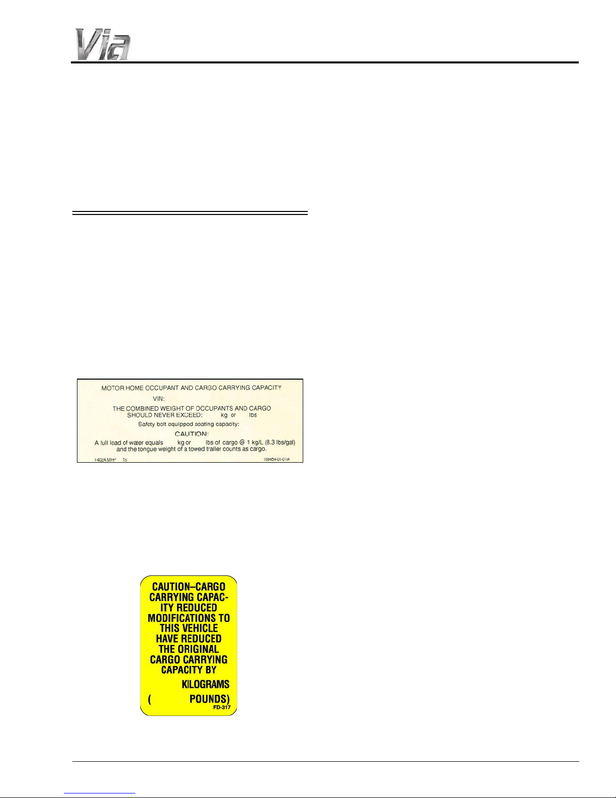
OCCUPANT AND CARGO
CARRYING CAPACITY LABEL
This label is affixed in the driver’s area next to
or near the Vehicle Certification Label. It
contains vehicle occupant and cargo carrying
capacity along with the number of seat belt
positions in the vehicle. The label also provides
the weight of a full load of water and advises that
this weight, along with the tongue weight counts
as cargo.
SECTION 1 –
INTRODUCTION
If any weight exceeding 45.4 kg (100 lbs.) is
added to your coach between final vehicle
certification and first retail sale, the occupant and
cargo carrying capacity must be corrected and a
label similar to the one shown below will be
affixed inside your coach.
1-3
SECTION 1 –
INTRODUCTION
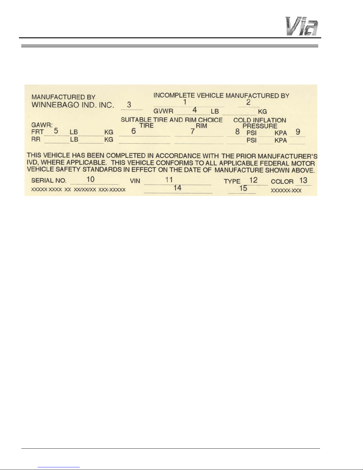
VEHICLE CERTIFICATION LABEL
This label is affixed to the lower driver side armrest panel, driver door, or the driver side door jamb,
depending on model. It contains vehicle identification numbers and other important reference information.
EXPLANATION OF DATA
1. Chassis manufacturer.
2. Chassis manufacture date.
3. Month and year of manufacture at Winnebago
Industries®.
4. Gross Vehicle Weight Rating: Total
permissible weight of the vehicle, including
driver, passengers, total cargo carried
(including all liquids), and equipped with all
options.
5. Gross Axle W eight Rating: Total permissible
weight allowed for the front and rear axles
(listed in pounds and kilograms).
6. Suitable Tire Choice: Tires recommended to
meet handling and safety requirements. When
replacing any of the tires on your vehicle,
always replace with a tire that meets these
specifications.
7. Suitable Rim Choice: Wheel rims
recommended to meet handling and safety
requirements. When replacing any of the rims
on your vehicle, always replace with a rim that
meets these specifications.
8. Cold Inflation Pressure: Inflation pressures at
Gross Axle Weight Ratings recommended
(while cold) for the tires originally equipped
on your vehicle. These pressure levels must be
maintained to assure proper handling, safety,
and fuel economy.
9. Rear Axle Wheel Configuration: Single or
Dual as it relates to the inflation.
10. Serial Number: This is the serial number
assigned to the completed vehicle by
Winnebago Industries.
11. Vehicle Identification Number (VIN): This
number identifies the chassis on which the
motorhome is built. The 10th digit of the VIN
designates the chassis model year. (C=2012,
D=2013, etc.). This information is useful
when ordering chassis repair parts.
12. Type: States the NHTSA designated usage
classification for your motorhome. MPV
signifies a Multi-purpose Passenger Vehicle.
13. Color: Signifies the color code number of the
decor used throughout the vehicle. This
number is necessary for ordering replacement
cushions, curtains, carpet, etc.
®
14. Winnebago
model year and series/family
name.
15. Model: Lists the Winnebago product model
number of your vehicle.
1-4

SPECIFICATIONS AND CAPACITIES
Benz® F50
Benz® F50
Benz® F50
Feature Number 1ME 1ME 1ME
Length 25' 5" 25' 5" 25' 5"
1
11' 11' 11'
Exterior Width 7' 6.25" 7' 6.25" 7' 6.25"
2
39.0 cu. ft. 54.0 cu. ft. 92.0 cu. ft.
Awning Length 16' 16' 16'
Interior Height 6' 5" 6' 5" 6' 5"
Interior Width 7' 3" 7' 3" 7' 3"
3
28 gal. 27 gal. 28 gal.
Water Heater Capacity 6 gal. 6 gal. 6 gal.
3
36 gal. 40 gal. 36 gal.
Holding Tank Capacity - Gray
3
36 gal. 30 gal. 36 gal.
4
13 gal. 13 gal. 13 gal.
Wheelbase 170" 170" 170"
GVWR 11,030 lbs. 11,030 lbs. 11,030 lbs.
GAWR - Front 4,410 lbs. 4,410 lbs. 4,410 lbs.
GAWR - Rear 7,720 lbs. 7,720 lbs. 7,720 lbs.
GCWR
5
15,250 lbs. 15,250 lbs. 15,250 lbs.
Fuel Capacity
100 liter
(26.4 gal.)
100 liter
(26.4 gal.)
100 liter
(26.4 gal.)
Actual towing capacity is dependent on your particular loading and towing circumstances which includes the GVWR, GAWR,
and GCWR as well as adequate trailer brakes. Refer to the chassis operator's manual of your motor home for further towing
Winnebago Via
Capacities shown are the tank manufacturer's listed water capacity (W.C.). Actual filled propane capacity is 80% of listing due
to overfilling prevention device on tank.
All measurements are based upon the most recent data available. See your dealer for specifications.
The height of each model is measured to the top of the tallest standard feature and is based on the curb weight of a typically
equipped unit. The actual height of your vehicle may vary by several inches depending on chassis or equipment variations.
2
The load capacity of your motor home is designated by weight, not by volume, so you cannot necessarily use all available space
when loading your motor home.
3
Capacities are based on measurements prior to tank installation. Slight capacity variations can result upon installation.
25Q 25R 25T
Mercedes-
Mercedes-
Mercedes-
SECTION 1 –
INTRODUCTION
Chassis
Chassis
Exterior Height
Exterior Storage
Freshwater Tank Capacity
Holding Tank Capacity - Black
Propane Capacity
Notes:
1
Contact your dealer for further information.
Chassis
4
5
information.
1-5

SECTION 1 –
INTRODUCTION
OWNER AND VEHICLE INFORMATION
OWNER INFO
Owner’s Name(s) __________________________________________________________________
Address __________________________________________________________________________
__________________________________________________________________________
VEHICLE INFORMATION
Motorhome Model Number __________________________________________________________
Motorhome Serial Number___________________________________________________________
Chassis Vehicle Identification No. (VIN)________________________________________________
Vehicle Mileage at Delivery __________________________________________________________
Selling Dealer Name________________________________________________________________
Address __________________________________________________________________________
__________________________________________________________________________
YOUR WINNEBAGO INDUSTRIES® DEALER /SERVICE CENTER
Name____________________________________________________________________________
Address __________________________________________________________________________
__________________________________________________________________________
Contact ____________________________________________Phone ________________________
CHASSIS SERVICE CENTER
Name____________________________________________________________________________
Address __________________________________________________________________________
__________________________________________________________________________
Contact ____________________________________________Phone ________________________
RV INSURANCE POLICY
Company_________________________________________________________________________
Policy Number ____________________________________________________________________
Agent______________________________________________Phone ________________________
1-6
SECTION 2 – SAFETY AND PRECAUTIONS
DANGER
GENERAL WARNINGS
• Only seats equipped with seat belts are to be
occupied while the vehicle is moving.
• Make sure all passengers have seat belts
fastened. Lap belts should fit low on the hips
and upper thighs. The shoulder belt should be
positioned snug over the shoulder.
• For pregnant women: Never place the
shoulder belt behind your back or under your
arm. Adjust the lap belt across your hips/
pelvis, and below your belly. Place the
shoulder belt across your chest (between your
breasts) and away from your neck.
• Child restraints should be installed properly
according to manufacturer’s instructions. See
“Child Restraints”.
• All moveable or swiveling seats should be
placed and locked in travel position while the
vehicle is moving.
• Never let passengers stand or kneel on seats
while the vehicle is moving.
• Use care when accelerating or decelerating on
a slippery surface. Abrupt speed changes can
cause skidding and loss of control.
• Never drive the vehicle with a slideout room
extended.
• Driving through water deep enough to wet the
brakes may affect stopping distance or cause
the vehicle to pull to one side. Check brake
operation in a safe area to be sure they have
not been affected. Never operate any vehicle if
a difference in braking efficiency is
noticeable.
• Adverse weather conditions and extremes in
terrain may affect handling and/or
performance of your vehicle. Refer to your
chassis manual for complete and related
information on driving your vehicle.
FUEL AND PROPANE GAS
• Sleeping facilities are not to be utilized while
vehicle is moving.
• Examine the escape window and be familiar
with its operation.
• Inspect the fire extinguisher monthly for
proper charge and operating condition. This
should also be done before beginning a
vacation or any extended trip.
DRIVING SAFETY
• Do not attempt to adjust the driver’s seat while
the vehicle is moving.
• Do not adjust tilt steering in a moving vehicle.
• Do not operate the cruise control on icy or
extremely wet roads, winding roads, in heavy
traffic, or in any other traffic situation where
a constant speed cannot be maintained.
All pilot lights, appliances, and their
ignitors (see operating instructions)
shall be turned off before refueling of
motor fuel tanks and/or propane
containers. Failure to comply could
result in death or serious injury.
5 - DASH / AUTO
2-1
SECTION 2 –
WARNING
SAFETY AND PRECAUTIONS
Propane gas containers, gasoline, or
other flammable liquids shall not be
placed or stored onboard the vehicle
because a fire or explosion may result.
Propane gas containers are equipped
with safety valves, which relieve
excessive pressure by discharging gas
to the atmosphere. Failure to comply
could result in death or serious injury.
• All pilot lights must be extinguished and
appliances turned off while refilling the fuel
tank or propane gas tank.
• Never smoke while refilling vehicle fuel tank
or propane gas tank.
• Never use an open flame to test for propane
gas leaks. Replace all protective covers and
caps on propane system after filling. Make
sure valve is closed and the door is latched
securely.
• Never connect natural gas to the propane gas
system.
• When lighting range burners, do not turn
burner controls to “On” and allow gas to
escape before lighting match.
• Portable fuel-burning equipment, including
wood and charcoal grills and stoves shall not
be used inside the recreational vehicle. The
use of this equipment inside the recreational
vehicle may cause fires or asphyxiation.
• Propane gas regulators must always be
installed with the diaphragm vent facing
downward. Regulators are equipped with a
protective cover. Make sure that the regulator
vent faces downward and that the cover is kept
in place to minimize vent blockage, which
could result in excessive gas pressure causing
fire or explosion.
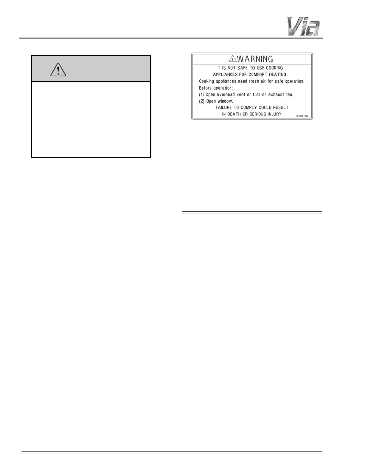
• The following warning label is located in the
cooking area to remind you to provide an
adequate supply of fresh air for combustion.
Unlike homes, the amount of oxygen supply is
limited due to the size of the recreational vehicle,
and proper ventilation when using the cooking
appliance(s) avoids dangers of asphyxiation. It is
especially important that cooking appliances not
be used for comfort heating, as the danger of
asphyxiation is greater when the appliance is
used for long periods of time. Failure to comply
could result in death or serious injury.
PROPANE GAS LEAKS
Check propane gas system for leaks yearly, or
as necessary.
The following procedures are noted on a label,
located in the vehicle near the range area. If you
smell gas within the vehicle, quickly and
carefully perform the procedures listed.
IF YOU SMELL PROPANE
• Extinguish any open flames, pilot lights, and
all smoking materials.
• Do not touch electrical switches.
• Shut off the gas supply at the tank valve(s) or
gas supply connection.
• Open doors and other ventilating openings.
• Leave the area until odor clears.
• Have the propane system checked and leakage
source corrected before using again.
Failure to comply could result in death or
serious injury.
2-2
PROPANE GAS LEAK
WARNING
Propane Gas Leak Detector
WARNING
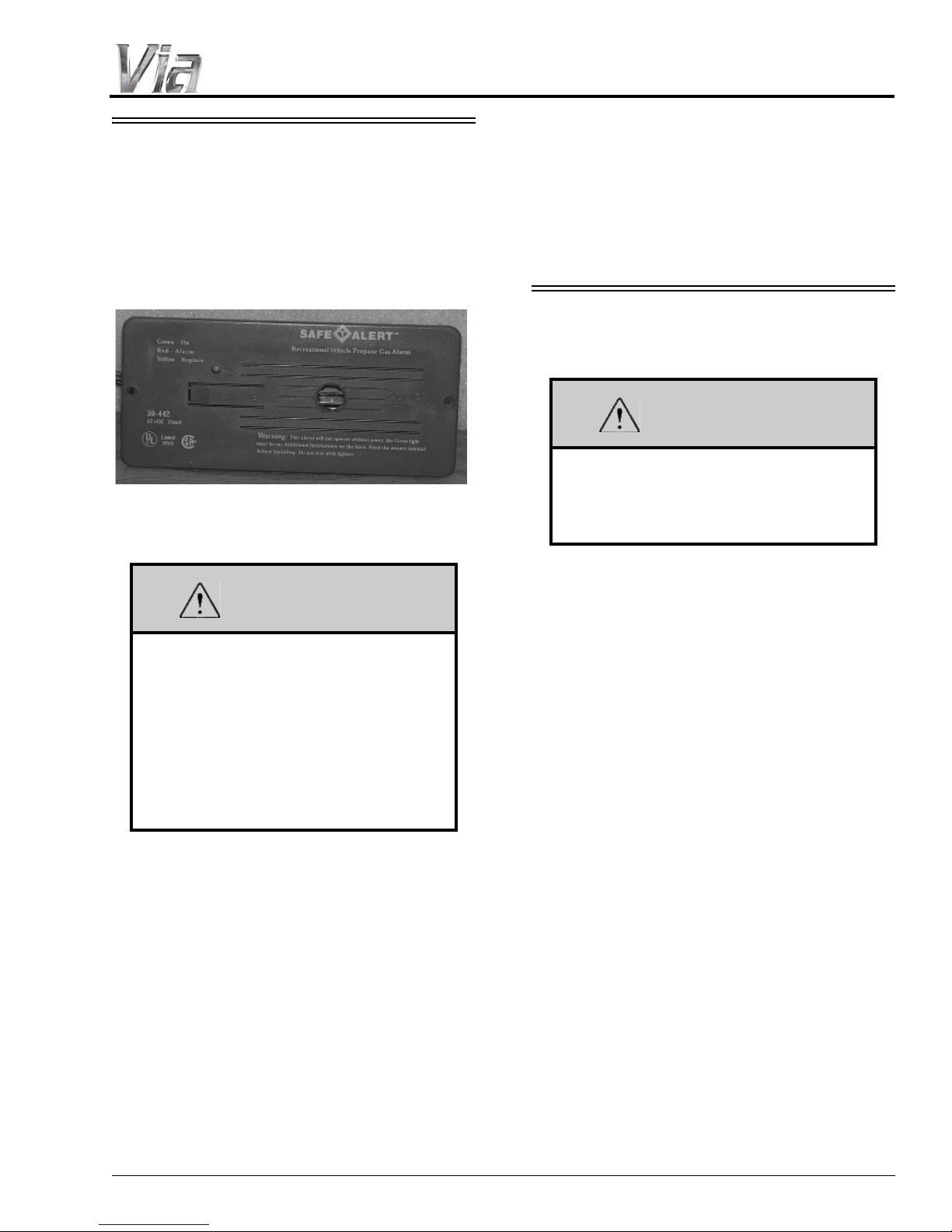
DETECTOR
Your coach is equipped with a Propane Gas
Leak Detector, similar to the one shown below.
The leak detector sounds an alarm if an unsafe
amount of propane gas is present inside the
coach.
SECTION 2 –
SAFETY AND PRECAUTIONS
battery during storage periods when the house
battery will not be charged regularly by the
engine or shoreline.
Further Information
See the manufacturer’s user guide provided in
your InfoCase for further instructions.
CARBON MONOXIDE
WARNING
Avoid inhaling exhaust gases, as they
contain carbon monoxide, which is a
colorless, odorless, and poisonous gas.
Death or serious injury can result.
EXPLOSION HAZARD: DO NOT use an
open flame to test for gas leaks. When
testing for gas line leaks with a soapy
water solution, DO NOT use a detergent
containing ammonia or chlorine. These
substances may generate a chemical
reaction causing corrosion to gas lines,
resulting in dangerous leak conditions.
Death or serious injury can result.
Power Connection
The Propane Gas Leak Detector is powered by
the house batteries. If the House/Coach Battery
Disconnect switch is shut off or the battery cable
is disconnected from the batteries, the alarm will
not work. The Propane Gas Leak Detector fuse or
circuit breaker is located in the 12-volt house
electrical load center.
Because the Propane Gas Leak Detector is
connected to the house battery, it is always
drawing a small amount of current. Even though
this current draw is slight, it could drain the house
The best protection against carbon monoxide
entry into the vehicle body is a properly
maintained engine exhaust and ventilation
system. It is recommended that the exhaust
system and body be inspected by a qualified
motorhome service center:
• Each time the vehicle is serviced for an oil
change.
• Whenever a change in the sound of the
exhaust system is noticed.
• Whenever the exhaust system, underbody , or
rear of the vehicle is damaged.
To allow proper operation of the vehicle’s
ventilation system, keep front ventilation inlet
grill clear of snow, leaves, or other obstructions
at all times. DO NOT OCCUPY A PARKED
VEHICLE WITH ENGINE RUNNING FOR
AN EXTENDED PERIOD.
Do not run engine in confined areas, such as a
garage, except to move vehicle into or out of the
area.
2-3
SECTION 2 –
WARNING
Press button to test
Carbon Monoxide Alarm
Smoke Alarm
Push button
to test
SAFETY AND PRECAUTIONS
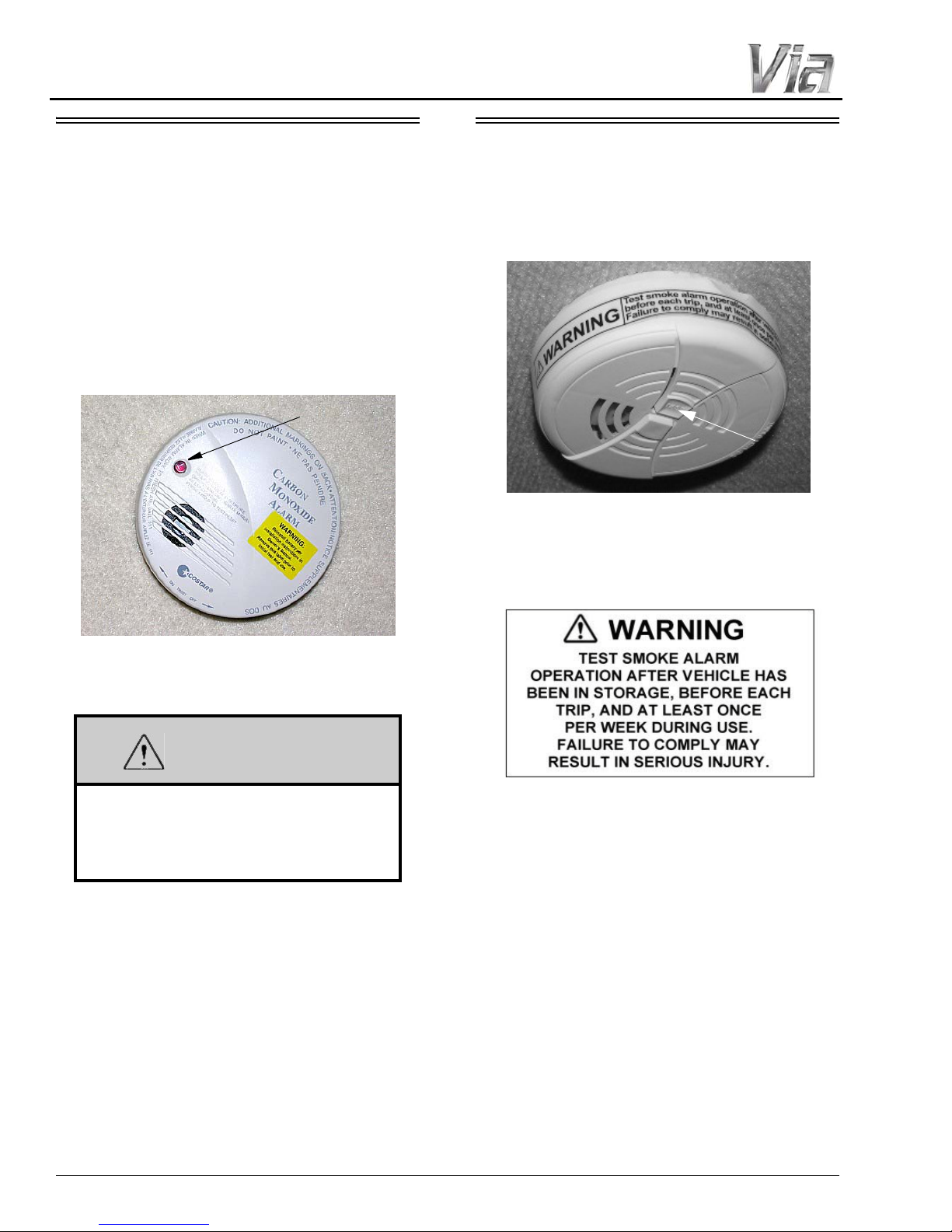
CARBON MONOXIDE ALARM
Your coach is equipped with a Carbon
Monoxide (CO) Alarm (located on the ceiling in
the bedroom area.) The CO Alarm is powered by
a 9-volt battery and has a sensor that is designed
to detect toxic carbon monoxide gas fumes
resulting from incomplete combustion of fuel. It
will detect CO gas from any combustion source
such as the furnace, gas range/oven, water heater,
refrigerator, chassis engine, and electric
generator engine.
SMOKE ALARM
Your coach is equipped with a Smoke Alarm
(located on the ceiling in the lounge area.) The
Smoke Alarm is powered by a 9-volt battery and
has a sensor that is designed to detect smoke.
The following label is affixed to the Smoke
Alarm.
Failure to replace this product by the
“REPLACE BY DATE” printed on the
alarm cover may result in death by
Carbon Monoxide poisoning.
Replacement
When replacing this alarm, we recommend
replacing only with the same model, or with one
that is also listed for RV application. We
recommend obtaining a replacement from your
Winnebago Industries
®
dealer.
Further Information
Please read the information provided by the
manufacturer, which is included in your InfoCase
for further information.
2-4
Replacement
When replacing this alarm, we recommend
replacing only with the same model, or with one
that is also listed for RV application. We
recommend obtaining a replacement from your
Winnebago Industries
®
dealer.
Further Information
See the manufacturer’s information in your
InfoCase for further instructions.
SECTION 2 –
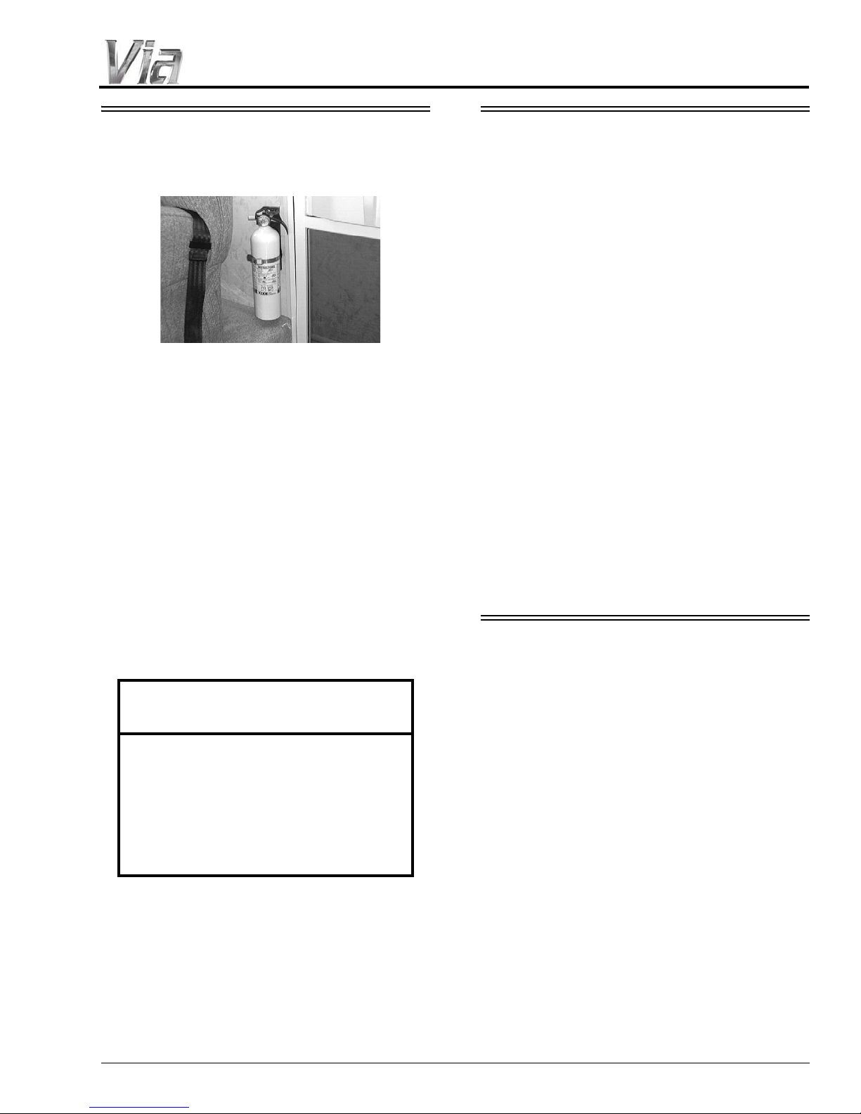
Fire Extinguisher
(Typical inst alla tion - your coach may
vary according to model and floorplan)
SAFETY AND PRECAUTIONS
FIRE EXTINGUISHER
A dry chemical Fire Extinguisher is located
near the main entrance door.
We recommend that you become thoroughly
familiar with the operating instructions displayed
on the side of the Fire Extinguisher and in the
information supplied in your InfoCase.
We also recommend that you inspect the Fire
Extinguisher for proper charge at least once a
month in accordance with National Fire
Protection Association (NFPA)
recommendations as stated on the label.
If the charge is insufficient, the Fire
Extinguisher must be replaced.
ELECTRICAL
• Careless handling of electrical components
can be fatal. Never touch or use electrical
components or appliances while feet are bare,
while hands are wet, or while standing in
water or on wet ground.
• Improper grounding of the vehicle can cause
personal injury . Do not plug the utility power
cord into an outlet which is not grounded and
do not adapt the plug to connect to a receptacle
for which it is not designed.
• Do not attach an extension cord to the utility
power cord.
• Do not use any electrical device that has had
the ground pin removed.
• A void overloading electrical circuits. Replace
fuses or circuit breakers with those of the
same size and amperage rating only. Never
use a higher rated fuse or breaker.
• Use caution when handling or working near
electrical storage batteries. Always remove
jewelry and wear protective clothing and eye
covering. Avoid creating sparks.
LOADING
NOTICE
Do not test the fire extinguisher by
discharging it. Partial discharge can
cause leakage of pressure or contents,
which would render the unit inoperative
when needed. When using the fire
extinguisher , aim the spray at the base of
the fire.
Replacement
If for any reason you must replace the Fire
Extinguisher, the replacement must be the same
type and size as the one originally supplied in
your coach. We recommend obtaining a
replacement only from your Winnebago
Industries® dealer or a reliable RV parts supplier.
• Store or secure all loose items inside the
motorhome before traveling. Possible
overlooked items such as canned goods or
small appliances on the countertop, cooking
pans on the range, or free-standing furniture
items can become dangerous projectiles
during a sudden stop.
• Be aware of GVWR, GAWR, and individual
load limit on each tire or set of duals (See
“Loading the Vehicle” in Section 12 -
Miscellaneous).
• Never load the motorhome in excess of the
gross vehicle weight rating of the gross axle
weight rating for either axle.
2-5
SECTION 2 –
Escape Window
(Lift latch handles upward
and push window open)
-Typical View
Pull latch UP to slide window open
-Typical View
SAFETY AND PRECAUTIONS
MAINTENANCE
• Do not remove the radiator cap while engine
and radiator are still hot. Always check
coolant level visually at the see-through
coolant reservoir.
• Never get beneath a vehicle that is held up by
a jack only.
• Do not mix different construction types of
tires on the vehicle, such as radial, bias, or
belted tires, as vehicle handling may be
affected. Replace tires with exact size, type,
and load range.
• Refer to your chassis manual for complete
maintenance precautions and
recommendations.
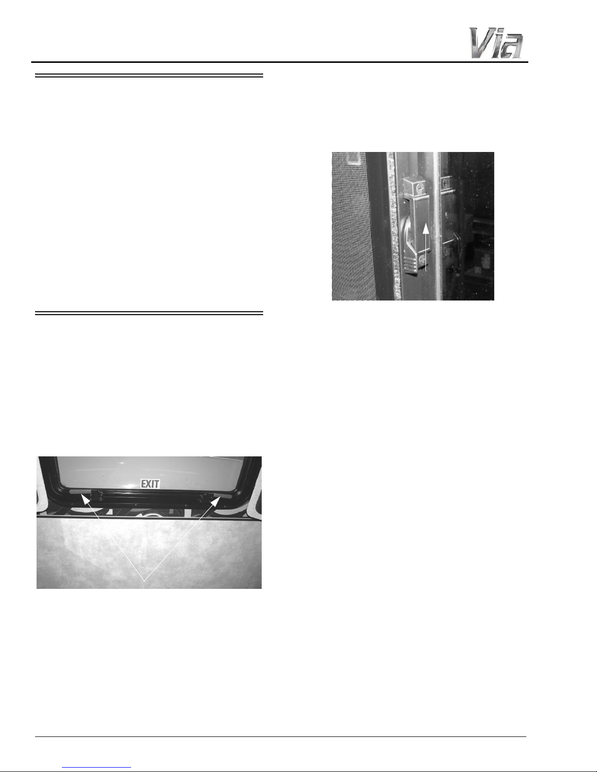
Using Slider Windows As
Emergency Exits
Some coaches are required to have a slider
window as an alternate exit. This window will be
marked EXIT and have a red-handled latch.
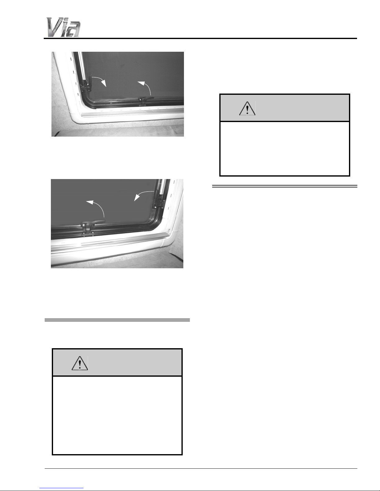
EMERGENCY EXITS
Escape Window
The bedroom escape window is secured by
two red safety latches at the bottom of the
window.
To open, lift both latches up and toward the
center of the window, then push outward near the
bottom of the window.
Most slider windows along the side of any
motorhome can also be used as alternate
emergency exits, should the need arise.
To use a slider windows as an exit, first slide
the window open, then either slide the screen
open or push the screen material out, depending
on window construction.
Escape Window (Optional)
-If Equipped
The bedroom escape window is secured by
four safety latches at the sides and bottoms of
each window.
To open, release all four latches and push
window out.
1. Side Latches (2) - Pull down toward bottom of
window frame.
2. Bottom Latches (2) - Pull toward the left-hand
side of the window frame.
3. Push window open.
2-6
WARNING
Escape Window
(View of interior left-hand side of window)
-Typical View
Side
Latch
Bottom
Latch
Escape Window
(View of interior right-hand side of window)
-Typical View
Side
Latch
Bottom
Latch
WARNING
SLIDEOUT ROOMS
Your motorhome may have more than
one slideout room. Understand which
switch operates which slideout room prior
to operation. Make sure all slideout rooms
are clear of people who could be harmed
or obstacles that could cause damage
prior to operating any slideout rooms.
Failure to observe can result in death or
serious injury.
SECTION 2 –
SAFETY AND PRECAUTIONS
Check inside and outside the vehicle to make
sure that there are no people who could be
harmed or obstacles that could cause damage due
to room activation.
Keep all persons clear of the slideout
room and moving parts while extending or
retracting. Do not occupy the slideout
room while it is being extended or
retracted. Failure to observe can result in
death or serious injury.
FORMALDEHYDE
INFORMATION
Some of the materials used in this recreational
vehicle emit formaldehyde. Eye, nose, and throat
irritation, headache, nausea, and a variety of
asthma-like symptoms, including shortness of
breath have been reported as a result of
formaldehyde exposure. Reaction to
formaldehyde exposure may vary among
individuals. Elderly persons and young children,
as well as anyone with a history of asthma,
allergies, or lung problems may be at greater risk.
Research is continuing on the possible long-term
effects of exposure to formaldehyde. Inadequate
ventilation may allow formaldehyde and other
contaminants to accumulate in indoor air.
Ventilation to dilute the indoor air may be
obtained from a passive or mechanical
ventilation system. Always be sure to thoroughly
ventilate your recreational vehicle before and
during each use. High indoor temperatures and
humidity may raise formaldehyde levels. When a
recreational vehicle is in areas subject to high
temperatures, an air conditioning system can be
used to control indoor temperature levels. If you
have any questions regarding the health effects of
formaldehyde, consult your doctor or local health
department.
2-7

SECTION 2 –
SAFETY AND PRECAUTIONS
MOLD, MOISTURE, AND YOUR
MOTOR HOME
Monitor your motorhome. Periodically check
those hidden areas in corners, closets, and
cabinets to assure mold is not present.
What is Mold?
Molds are part of the natural environment.
They are as old as the Earth itself and mold
spores are almost everywhere at some level
waiting to grow. Mold plays a part of nature by
breaking down dead organic matter, such as
fallen leaves and dead trees. Indoors however,
mold growth should be avoided. Molds
reproduce by means of tiny spores. Those spores
are invisible to the naked eye and float
throughout the outdoor and indoor air. Because
of the nature of the use of a motorhome, it is
natural for a motorhome to be introduced into an
environment with mold spores.
Mold is a plant and requires its own special
environment to grow. That environment includes
organic materials, nutrients, moisture, and proper
temperature.
How Can I Avoid Mold?
To reduce the ability for mold to grow, you
must reduce what constitutes its growth
environment. Mold can grow with the smallest of
a nutrient base. Just small amounts of dirt or dust
on the carpet can be enough to allow the mold
process to begin. Keep the environment as clean
as possible. Vacuum the carpet. Clean food spills
thoroughly and quickly. Avoid grease buildup
near the stove or sink. Clean the exhaust fan
above the stove often.
Minimize moisture in your motorhome and
keep humidity low. Clean spills quickly. Do not
allow condensation to build up. You can open
windows and vents to minimize condensation.
Use of the air conditioner can assist in removing
moisture from the air. Avoid leaks, but if leaks do
occur, make repairs promptly.
Avoid bringing mold into your motorhome.
Plants, cloths, books, and other household items
may already have mold present. It is easy to
transfer mold into your motorhome environment.
What if I Find Mold?
If mold develops, clean the area with a
concentrate of soap and bleach. Items that
contain mold that cannot be cleaned should be
removed from the vehicle.
Can Mold Harm Me?
The effects of mold and airborne mold spores
may cause irritation to some people. Experts
disagree on the level of exposure that may cause
health concerns.
If Mold Is Present, What Will
®
Winnebago Industries
If Winnebago Industries determines that mold
is present in the Winnebago®/Itasca® motorhome
as a result of a manufacturing defect reported to
Winnebago Industries within the limited
warranty period, Winnebago will clean the
affected area(s) and/or replace affected items as it
deems necessary. This is the extent of coverage
provided by Winnebago Industries. Winnebago
Industries, however, will not assume
responsibility for mold deemed to be a result of a
motorhome users lack of timely and appropriate
action to mitigate circumstances should a
problem occur.
If Winnebago Industries determines that mold
is present due to conditions it determines is not a
result of a manufacturing defect found within the
warranty period, Winnebago Industries will not
provide any financial assistance to the repair of
the condition.
Do?
ROADSIDE EMERGENCY
Because of the size and weight of this vehicle
and its tires, and the possible complications
involved in tire changing, we strongly advise
obtaining professional road service to change a
flat tire whenever possible. However, if an
emergency requires you to change the tire
2-8
SECTION 2 –
CAUTION
SAFETY AND PRECAUTIONS
yourself, please exercise extreme caution and
read all tire changing information in the chassis
manual.
Never get beneath a vehicle that is held up by
a jack only.
If You Get A Flat Tire
• DO NOT panic.
• Grip the steering wheel firmly and steer the
vehicle as straight as possible. Avoid quick
maneuvers. You may need to counter-steer to
compensate for “pull” created by the failed
tire.
• DO NOT stomp on the brake. This abruptly
shifts the vehicle’s weight forward, making it
nose-dive and pull toward the blown-out side.
• DO NOT jerk your foot off the accelerator.
Just ease back on the accelerator slowly and
gently to continue momentum. The deflated
tire will slow the vehicle.
• If you must change lanes to get to a safe
stopping place, use your signals to warn other
motorists and change lanes smoothly and
carefully after you are certain the lane is clear .
• Let the vehicle coast to a stop, gently steering
to a safe stopping place off the traffic lanes of
the road. Do not worry about damaging the
tire or wheel rim by driving on it. A tire or
wheel replacement is cheaper than damaging
the vehicle or injuring yourself.
• When you have come to a stop, activate your
hazard flashers to warn other motorists, then
exit the vehicle carefully.
• Set out flares or other warning devices.
Check your tires for proper inflation before
each trip and at least once a month with an
accurate tire gauge.
Some models, however, may have a swingdown spare tire carrier beneath the rear of the
coach. Please follow all safety warnings and
instructions for removing spare tire from the
carrier.
Swing-Down Carrier (if equipped)
Do not lie beneath tire carrier while
removing tire. The tire can fall and injury
can occur.
• Support tire carrier with a jack or block while
removing wire pin and wing nut from bolt at
back of carrier.
• Carefully lower tire carrier to ground.
• Lift or slide tire from carrier.
• Do not over-tighten wing nut when returning
carrier to storage position.
Recovery Towing
When calling a professional towing service,
we recommend that you advise them of your
coach length and approximate front axle weight
listed on your Vehicle Certification Label. This
will allow the towing operator to determine the
proper towing equipment to use.
Winnebago Industries® does not assume
responsibility for damage incurred while towing
this vehicle.
NOTE: Consult your chassis manual for towing
instructions or precautions provided by
the chassis manufacturer.
Spare Tire Storage
If your coach is supplied with a spare tire, it is
located in the rear storage compartment. Remove
wing nut from inside tire rim and lift or slide tire
out.
NOTICE
Do not lift on bumper . Damage will result
to front end body parts.
2-9
SECTION 2 –
WARNING
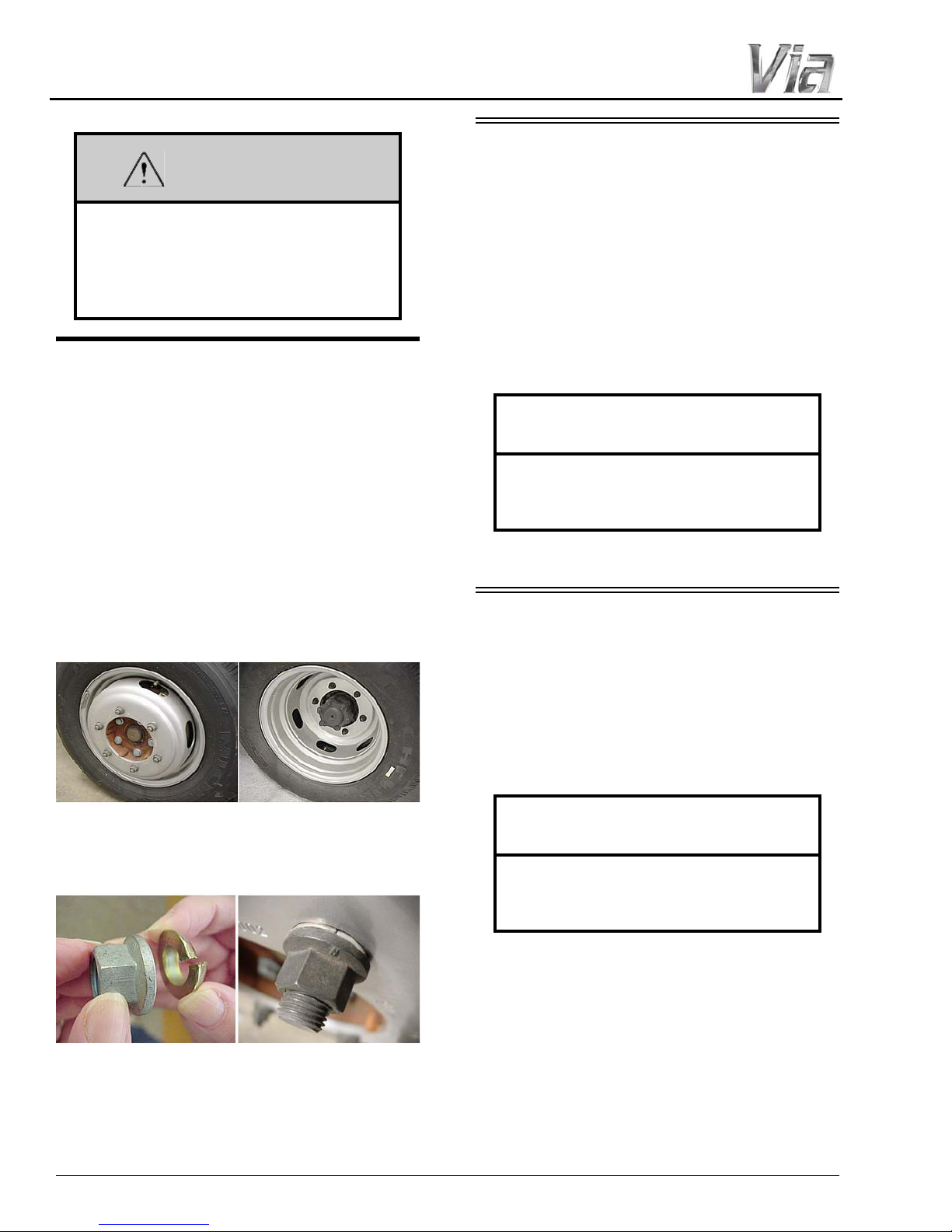
Steel Wheel Front Steel Wheel Rear
Steel Wheel Lug Nut and Washer
(Hex Flange Nut with Split Cone Washer)
SAFETY AND PRECAUTIONS
Stay out from beneath the motorhome
while it is suspended by the towing
assembly. Do not allow passengers to
occupy a towed vehicle. Death or serious
injury can result.
WHEEL MOUNTING NUTS
(LUG NUTS)
The mounting bolts and nuts for the standard
steel wheels are designed specifically for the type
of wheel. See the following information and
photos.
Steel Wheels
• The lug nut for steel wheels is a non-plated,
hat-shaped, flange nut. The accompanying
dome-shaped, split cone washer should be
positioned ‘dome first’ onto the wheel stud
before the nut as shown.
JUMP STARTING
If your coach will not start from the chassis
battery, try using the Battery Boost switch to
divert power from the house batteries to the
starter. (See “Battery Boost Switch” in Section 3
- Driving Your Motor Home).
If you wish to try jump starting the engine
using another vehicle or booster system, see your
chassis manual for connecting jumper cables to
the automotive electrical system.
NOTICE
Do not attempt to push start this vehicle.
Damage to the transmission or other
parts of the vehicle will occur.
ENGINE OVERHEAT
If you see or hear steam escaping from the
engine compartment or have any other reason to
suspect an extreme engine overheating condition,
pull the vehicle over to the roadside as soon as it
is safe to do so, stop the engine, and get all
passengers out of the vehicle.
2-10
NOTICE
Operating a vehicle under a severe
overheating condition can result in
damage to the vehicle.
For information on what to do in case of
overheating, consult your chassis manual.
SECTION 3 – DRIVING YOUR MOTOR HOME
Foot
Pedal
Activation
Switch
The information in this section refers only to
features installed or adapted to the dash and
driver compartment area by Winnebago
Industries®. It also includes passenger seating in
the living area of the coach.
Further Information
See the chassis manual in your InfoCase for
all original chassis related controls,
instrumentation, switches, and other features.
This includes items such as cruise control,
climate controls, gauges, wipers, lights, front
seats, and three-point safety belts, etc.
SEATS – DRIVER/CO-PILOT
(CHASSIS SUPPLIED)
-If Equipped
The driver and co-pilot seats may be
independently adjusted to suit individual
preference.
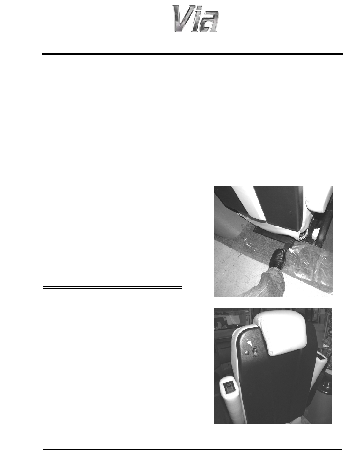
Pedestal Lift Operation
Raising the Seat
1. Assure the ignition key is in the “Accessory”
position and set the parking brake (refer to the
chassis operating manual provided in your
InfoCase).
2. Depress the Foot Pedal (located on the lower
back of the seat) and press and hold the
Activation switch (located on the back of the
seat) UP simultaneously until seat lift motion
stops.
3. Release Activation switch and Foot Pedal.
Further Information
See the chassis manual in your InfoCase for
instructions on seat adjustments.
SEATS – DRIVER/CO-PILOT
(FLEXSTEEL)
-If Equipped
The Driver and Co-pilot Seats may be
independently adjusted to suit individual
preference.
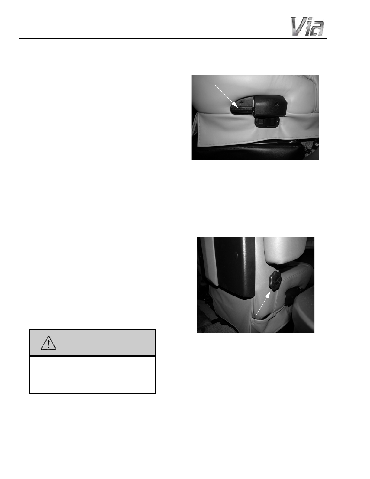
To move the seat forward or backward, lift the
slide release paddle (located on the outboard side
of the seat) and exert slight body pressure in the
direction desired.
The swivel/lift feature allows the seats to be
turned toward the living area for additional
seating while the unit is parked.
5 - DASH / AUTO
4. Remove key from ignition.
3-1
SECTION 3 –
WARNING
Recline Lever
Lumbar Adjustment Dial
(Located on the side of driver and
passenger seats)
• Adjust dial by rotating for lumbar tension
that best suits your comfort needs
DRIVING YOUR MOTOR HOME
Rotating the Seat T oward Center of Coach
If you wish to rotate the seats toward the
center of the coach for additional lounge/dinette
seating, follow Steps 1-3 as previously listed and:
5. Grasp front of seat and rotate around so the
seat is facing the lounge area, as desired.
Lowering the Seat
1. Grasp front of seat and rotate to the forward
facing position.
NOTE: Seat must be facing forward before
lowering. Failure to comply may r esult in
damage to the seat.
2. Assure the ignition key is in the “Accessory”
position.
3. Depress the Foot Pedal and press and hold the
Activation switch DOWN simultaneously
until seat fully lowers and front lock tab is
fully engaged (see supplied cab seat
manufacturer’s information for further
details).
4. Release Activation switch and Foot Pedal.
5. V erify that the front lock tab and the rear lock
are properly engaged.
6. Release the parking brake.
7. Remove key from ignition.
position, lift UP on the Recline Lever and lean
body forward. Allow the seat to return to the
desired position and release the lever.
Lumbar Support
Maintaining correct, ergonomic posture can
help prevent back pain and discomfort, so sitting
in a seat with good lumbar support is important.
A lumbar adjustment dial is located on the
side of the driver and passenger seats to provide
the travel comfort you need.
NOTE: A warning chime will sound if the seats
are not locked in the forward facing
position while attempting to start the
vehicle.
Assure seat is in its forward and locked
position for travel. Do not adjust seat
while vehicle is in motion. Failure to
comply may result in injuries.
Reclining the Seat
Lift UP on the Recline Lever (located on the
side of the seat), lean back to desired incline, and
release the lever. To return to the upright
3-2
SEAT BELTS
Seats intended for occupancy while the
vehicle is in motion are equipped with seat belts
for the protection of the driver and passengers.
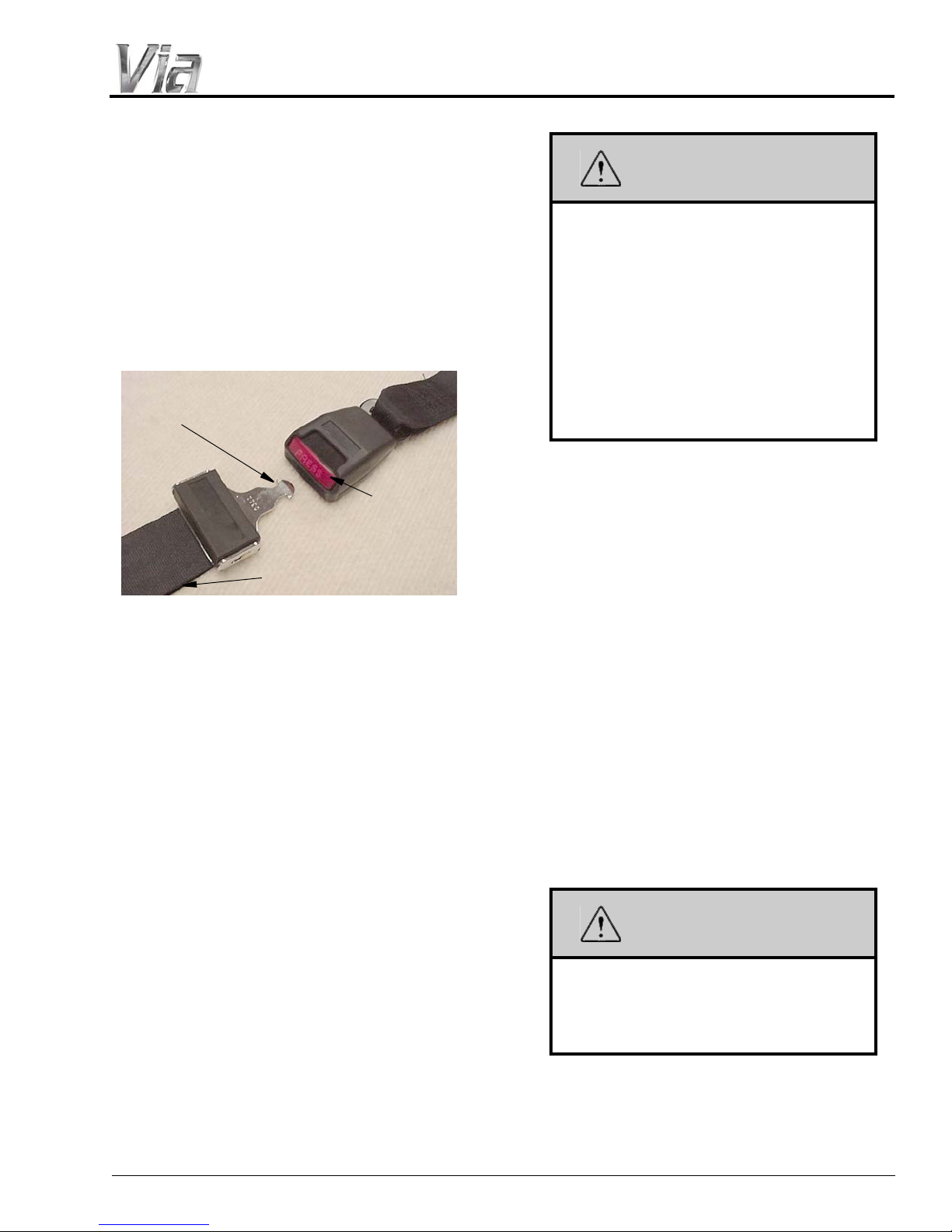
Lap Belts
1- Insert tab into buckle
slot until it “clicks” and is
locked
2- Pull strap to tighten
3- Press to
release
WARNING
WARNING
The lap belts must be worn as low as possible
and fit snugly across the hip area. Always sit
erect and well back into the seat. To gain full
protection of the safety belt, never let more than
one person use the same safety belt at any one
time, and do not let the safety belts become
damaged by pinching them in the doors or in the
seat mechanism. After any serious accident, any
seat belts which were in use at the time must be
inspected and replaced if necessary.
SECTION 3 –
DRIVING YOUR MOTOR HOME
Snug and low belt positions are essential.
This will ensure that the force exerted by
the lap belt in a collision is spread over the
strong hip area and not across the
abdomen, which could result in serious
injury.
Only seats equipped with seat belts are to
be occupied while vehicle is in motion.
Swivel seats must be in the locked,
forward facing position while vehicle is in
motion.
Lap/Shoulder Belts
Fastening
Hold the belt just behind the tongue. Next,
bring the belt across the body and insert the
tongue into the buckle until the latch engages.
Adjustment
To lengthen belt, swivel the tab end at a right
angle to belt and pull strap to desired length. To
shorten, pull loose end of belt.
To Fasten
Be sure belt is not twisted. Grasp each part of
the belt assembly and push tongue into buckle.
Adjust to a snug fit by pulling the loose end away
from the tongue.
To Release
Press button in center of buckle and slide
tongue out of buckle.
Unfastening
Press the release button in the buckle. Hold
onto the tongue when you release it from the
buckle to keep it from retracting too rapidly.
When the lap-shoulder belt is in use, the lap
belt must ride low across the hip area and the
shoulder belt must ride diagonally over the
shoulder toward the buckle.
The shoulder belt is designed to lock only
during a sudden stop, sudden body movement or
a collision. At all other times it will move freely
with the occupant.
Never wear the shoulder belt in any
position other than as stated above.
Failure to do so could increase the
chance or extent of injury in a collision.
Seat Belt Care and Cleaning
• Be careful not to damage the belt webbing and
hardware. Take care not to pinch them in the
seat or doors.
3-3
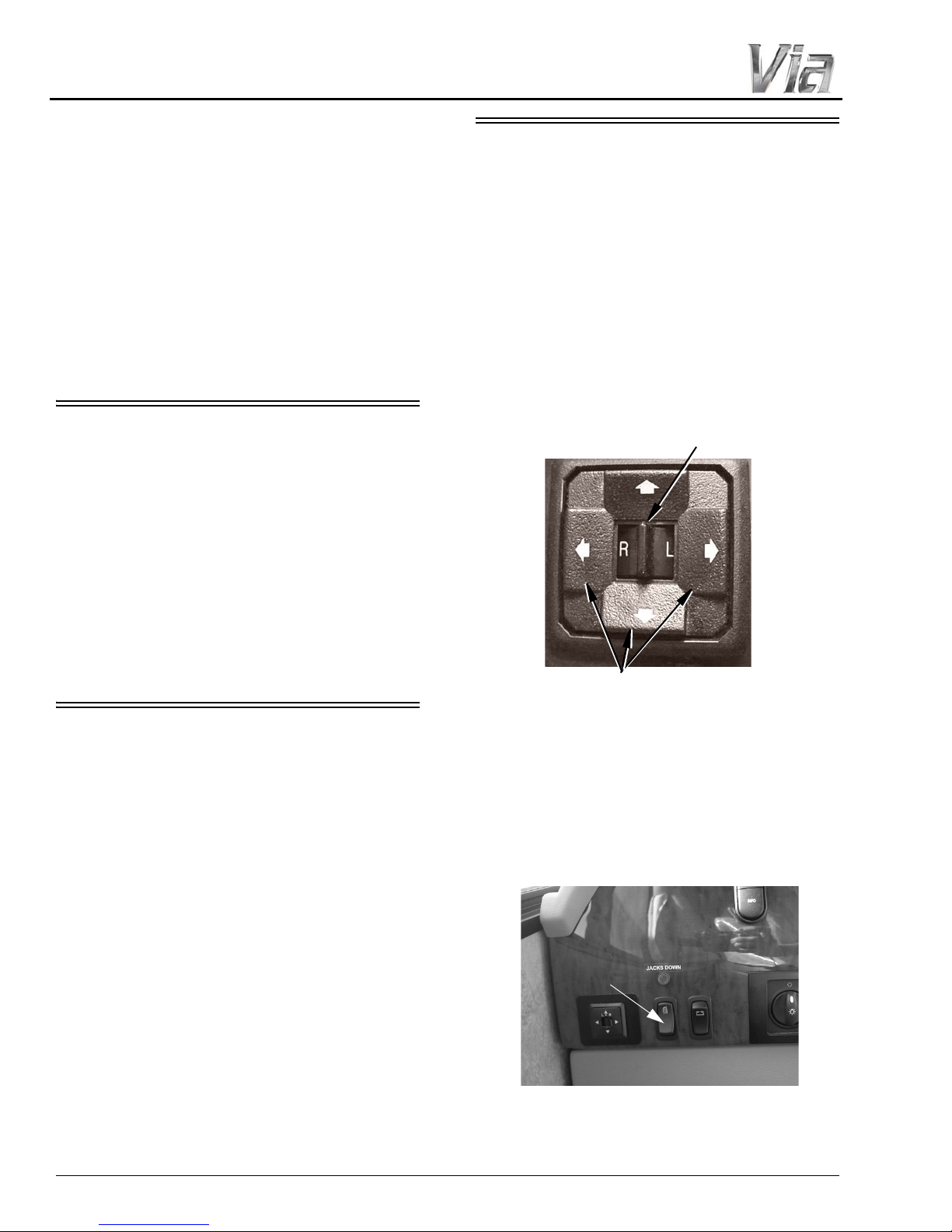
SECTION 3 –
Move Selector Switch L or R to select mirror.
Center “neutral” position disables arrows
to avoid unintentionally moving a mirror.
Press Arrow Buttons to move
mirror surface in direction indicated.
Mirror Heat Switch
(Located on dash)
-Typical View
DRIVING YOUR MOTOR HOME
• Inspect the belts and hardware periodically.
Check for cuts, frays, and loose parts.
Damaged parts should be replaced. Do not
remove or modify the belt system.
• Keep belts clean and dry. If the belts need
cleaning, use only a mild soap and water
solution. Do not use hot water. Do not use
abrasive cleaners, bleach, or dyes. These
products may weaken the belts.
• Replace any belt assembly that was used
during a severe impact. Replace the complete
assembly even if damage is not apparent.
KEYS
Your motorhome is supplied with several
keys. In addition to the chassis manufacturer’s
ignition key, you receive keys for the entrance
door and exterior compartment doors.
Keys have an identification number, either a
small metal tag or stamped into the key head.
These numbers are recorded on the vehicle’s
component model/serial sheet, which is included
in your InfoCase. In case keys are lost or stolen,
your dealer or a locksmith can provide you with
duplicate keys or modify the locks.
MIRRORS – POWER ELECTRIC
–If Equipped
Always adjust mirrors for maximum rear
visibility before driving off. Make sure the seat is
adjusted for proper vehicle control and that you
are sitting back squarely into the seat.
Mirror Adjustment Control
The mirror control is located on the driver side
armrest panel or the dash. The ignition key must
be on to adjust the mirrors.
REMOTE KEYLESS ENTRY
The main entry door on your vehicle is
equipped with a Remote Keyless Entry system. If
your coach is featured with a driver door, it also
will be equipped with this system. Use the
provided keyless remote transmitter to lock and
unlock the entry door as well as the driver door (if
equipped).
Make a habit of having the keys with you
when you exit the vehicle and if opening the
driver door (if equipped), first before opening the
entry door whenever unlocking with the keyless
remote.
Mirror Heaters
The mirrors may also contain heating
elements to de-fog or de-ice the mirror glass
during cold weather operation. A switch for the
mirror heaters is located on the dash. To turn on,
press the switch UP. Press DOWN to turn off.
3-4
Mirror Arm/Head Adjustment
Mirror Head Pivot Lock
• Loosen Allen head set
screws to pivot mirror head.
• Torque 75-100 in./lbs.
Power Sunvisor Switch
(Located beneath dash radio)
-Typical View
If you cannot adjust a mirror properly using
the control switch, the mirror may need a coarse
adjustment by rotating the mirror head.
SECTION 3 –
DRIVING YOUR MOTOR HOME
HAZARD WARNING FLASHERS
The hazard warning flashers provide
additional safety when the vehicle must be
stopped on the side of the roadway and presents a
possible hazard to other motorists. When the
flashers are on, it serves as a warning to other
drivers.
NOTE: Set screws may be located on the
opposite side of the mirror arm.
Passenger side mirror is similar.
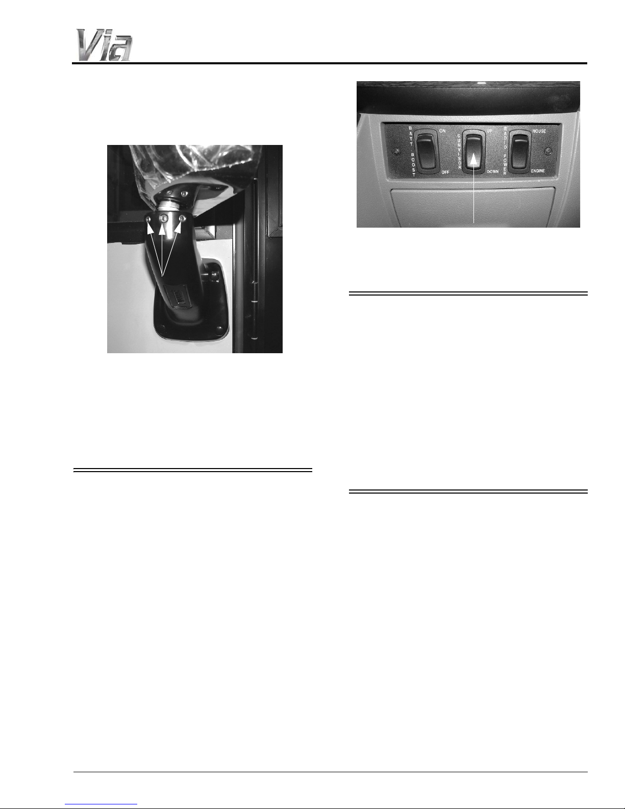
POWER SUNVISOR
-If Equipped
The Power Sunvisor is controlled by a switch
located beneath the dash radio.
• T o extend, Press and Hold the Power Sunvisor
switch in the DOWN position.
• T o retract, Press and Hold the Power Sunvisor
switch in the UP position.
NOTE: Do not position the visor where it will
impair the driver’ s forwar d vision or side
mirror views.
Further Information
See your chassis manual for instructions on
activating, operating, and canceling hazard
warning flashers.
AIR CONDITIONER/HEATER –
AUTOMOTIVE (DASH)
See the chassis manual provided in your
InfoCase for specific recommendations,
operating instructions, and maintenance
information.
NOTE: The dash air conditioner is not designed
to cool the entire interior of the coach,
but is intended only to provide cooling
for the cab area.
Accessing the AC/Heater Filter
The dash AC/heater is equipped with a
disposable filter, which is located underneath the
front hood. To access the filter:
1. Open the front hood.
3-5
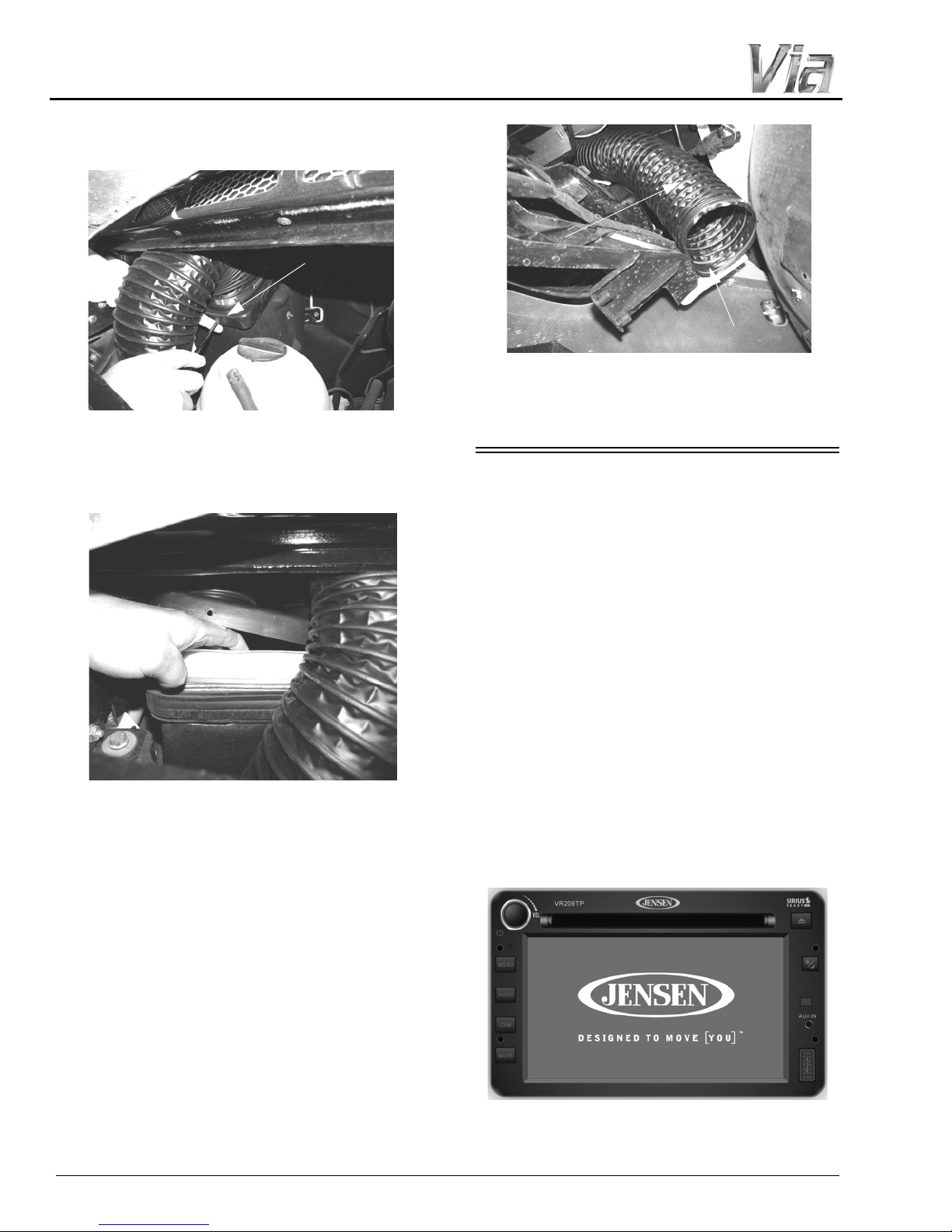
SECTION 3 –
Air Filter Housing
(Located underneath the front hood)
Air Intake Hose/Fastener
(View shown from beneath
the front end of coach)
Fastener
Air Intake
Hose
DRIVING YOUR MOTOR HOME
2. Remove two screws on the front of the air
filter housing.
3. Lift up air filter housing lid and replace filter.
NOTE: To make removing the air filter easier,
you may temporarily move the air intake
hose by removing the fastener as shown
in the following photo.
When finished replacing the filter, be
sure to put air intake hose back in place
and resecure the fastener.
RADIO IN-DASH/REARVIEW
MONITOR SYSTEM
–If Equipped
The radio in your coach can receive AM/FM
stereo and weather band stations. It also has a
compact disc (CD) player for your listening
enjoyment through quality high-output speakers
located in several areas of the coach.
This system is also featured with a rearview
camera monitor system, which lets you see what
is directly behind your coach for safety and
maneuvering assistance. The viewing screen is
integrated into the dash.
The monitor screen “wakes up” automatically
when transmission is shifted into reverse. A
microphone built into the rear camera lets you
hear warning sounds or verbal directions from an
assistant.
3-6

SECTION 3 –
iPod Cable
(Located in compartment above dash radio)
-Typical Installation
DRIVING YOUR MOTOR HOME
Basic Operating Instructions
• POWER ON/OFF - Push
to turn ON or OFF. Push
and Hold to turn screen
OFF. Touch screen to turn
back ON.
• MENU - Press to access USER SETTING
MENU. Press and Hold to access SYSTEM
SETUP MENU.
• AUDIO - Press and Hold to access AUDIO
MENU. Press to return to current playback
mode.
• CAM - Press to access CAMERA mode.
Press and Hold to access CAMERA
SETTINGS MENU.
• MUTE - Press to MUTE audio.
• EJECT - Press to EJECT
CD.
• DAY/NIGHT - Press to
switch between stored
DAY/NIGHT user settings.
Press and Hold to access
AUTO DAY/NIGHT adjust.
Satellite Radio
–If Equipped
Your coach may be equipped with a Sirius®
satellite radio receiver that plays through your
radio.
See the receiver manufacturer’s information
in your InfoCase for programming and operating
instructions.
iPod Cable
-If Equipped
Your coach may be equipped with a cable to
connect your iPod to play through your radio.
This cable is in the pocket located above the dash.
• AUX IN - Connect portable
audio player.
• USB - Connect a USB Jump
Drive. NOT FOR IPOD
CONTROLS.
Sideview Cameras
–If Equipped
The sideview cameras (built into the driver
and passenger side mirrors) activate with the
corresponding turn signals and replace the rear
camera view on the monitor until the turn is
completed or the signal lever is canceled
manually.
See the manufacturer’s information in your
InfoCase for operating instructions.
Radio Remote Controls
A hand-held remote allows the passenger to
change radio stations or CD selections from the
convenience of their seat. The hand-held radio
remote is included in your InfoCase.
Radio Power Switch
The Radio Power switch on the dash lets you
connect the dash radio to the coach batteries
when the ignition switch turned off for listening
while parked. This prevents accidental draining
of the chassis battery by prolonged use of the
radio.
NOTE:The House/Coach Battery Disconnect
switch must be ON while listening to the
dash radio, as the audio relay is power ed
3-7
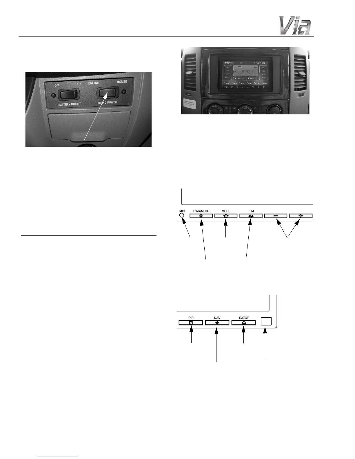
SECTION 3 –
Radio Power Switch
(Located on lower dash area)
• Press HOUSE to listen to the radio while
parked without the ignition key on.
• Press ENGINE (“ENG”) to listen while driving.
Radio/GPS/Rearview Monitor
(Located on dash)
• Power
ON-OFF/
Mute
• Mode
(Main
Menu)
•Dim
• Volume
DOWN/
UP
• Bluetooth
Mic
•Picturein-Picture
• Navigation
•Eject
•IR Receiver
DRIVING YOUR MOTOR HOME
by house batteries. If the House/Coach
Battery Disconnect switch is OFF, the
speakers will not emit sound.
Basic Operating Instructions
Refer to the manufacturer’s owner manual
and/or quick start guide provided in your
InfoCase for a complete explanation of features
and operating/set-up instructions.
Further Information
See the manufacturer’s user guide provided in
your InfoCase for complete operating
instructions.
INFOTAINMENT CENTER/GPS
–If Equipped
The Infotainment Center in your coach is an
all-in-one system that offers dash radio, rearview
monitor, and GPS capability for your travel
convenience.
®
This system also features Sirius
radio, iPod and USB connections, and DVD
player.
NOTE: As a safety feature, this system will not
play DVD’s unless the Parking Brake is
set.
satellite
3-8
NOTE: Your Infotainment Center is featured
with an exterior thermometer. The
temperature shown on the Infotainment
Center display screen and the
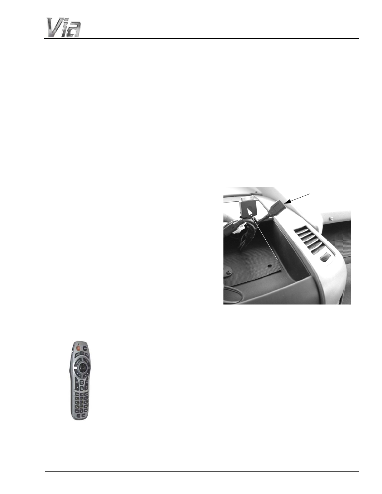
SECTION 3 –
Dash Radio/
GPS Remote
iPod/USB Connections
(Located in dash compartment above radio)
iPod
Connection
USB
DRIVING YOUR MOTOR HOME
temperature shown on the dash
instrument panel may vary by up to three
degrees.
Rearview Monitor
The rearview monitor feature of this system
lets you see what is directly behind your coach
for safety and maneuvering assistance. Sideview
cameras also allow you to see what is beside you
before turning or changing lanes.
The monitor automatically changes to camera
mode when transmission is shifted into reverse.
A microphone built into the rear camera lets you
hear warning sounds or verbal directions from an
assistant.
Sideview Cameras
The sideview cameras (built into the driver and
passenger side mirrors) activate with the
corresponding turn signals and replace the rear
camera view on the monitor until the turn is
completed or the signal lever is canceled
manually.
See the receiver manufacturer’s information
in your InfoCase for programming and operating
instructions.
iPod Connection
Your coach is equipped with an iPod
connection (located in the dash compartment
above radio) to play your iPod through the dash
radio.
USB Connection
Your coach is equipped with a USB
connection (located in dash compartment above
radio) to connect items such as video game
consoles, digital cameras, smartphones, printers,
etc.
GPS
The GPS navigation system can help you
confidently chart your course through the most
dense concrete jungle or remote country
backroad using global satellite positioning
technology.
Navigational information can be displayed on
the monitor using either the monitor itself, or the
remote control.
Satellite Radio
Your coach is equipped with a Sirius® satellite
radio receiver that plays through your radio.
Radio Power Switch
The Radio Power switch lets you connect the
dash radio to the coach batteries with the ignition
switch turned off for listening while parked. This
prevents accidental draining of the chassis
battery with prolonged use of the radio.
NOTE:The House/Coach Battery Disconnect
switch must be ON while listening to the
dash radio because the audio relay is
powered by house batteries. If the House/
Coach Battery Disconnect switch is OFF,
the speakers will not emit sound.
3-9
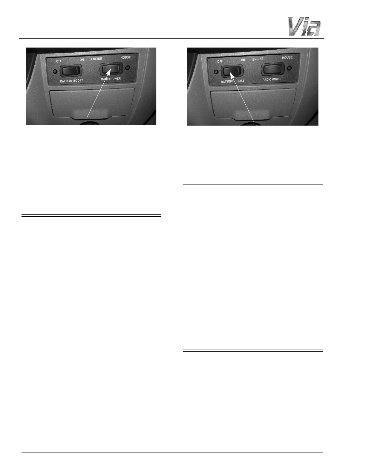
SECTION 3 –
Radio Power Switch
(Located on lower dash area)
• Press HOUSE to listen to the radio while
parked without the ignition key on.
• Press ENGINE (“ENG”) to listen while driving.
Battery Boost Switch
(Located on lower dash area)
• Press and Hold in the ON position while
turning ignition key for emergency
starting power.
DRIVING YOUR MOTOR HOME
Further Information
See the manufacturer’s user guide provided in
your InfoCase for complete operating
instructions.
BATTERY BOOST SWITCH
The Battery Boost switch can be used to draw
emergency starting power from the house
batteries to start the engine if the chassis battery
is discharged.
Press and Hold the Battery Boost switch in the
ON position while turning ignition key for
emergency starting power.
NOTE: The House/Coach Battery Disconnect
switch near the entrance door must be
ON and house batteries must be
sufficiently charged for this feature to
work.
ENGINE COOLING SYSTEM
Do not remove the radiator cap while engine
and radiator are still hot. Always check coolant
level visually at the see-through coolant
reservoir.
NOTE: Your chassis engine cooling system is
filled with special extended-life coolant
that is not the same as common antifreeze available at retail outlets.
The coolant system MUST be refilled or
topped up with the same type of coolant
as equipped to maintain the special longlife properties.
Further Information
Refer to the chassis manual in your InfoCase
for information and precautions on filling,
servicing, and checking the fluid level.
3-10
FUEL FILL ACCESS
The fuel fill access is located directly behind
the driver side door on the exterior of the coach.
Use the small round key (attached to your key
ring) to unlock the fuel fill door.
• Insert key into lock turning counter-clockwise
to unlock and open door.
 Loading...