

Winnebago Sunflyer (2001), Sunflyer 34Y (2001), Sunflyer 35U (2001), Sunflyer 36W (2001), Sunflyer 36L (2001) User Manual

TO THE OWNER
Congratulations! We welcome you to the exciting world of motor home travel and camping. You will
find it convenient and enjoyable to have all the comforts of home and still enjoy the great outdoors wherever you choose to go.
Your motor home has been carefully designed, engineered and manufactured to provide dependability
as well as safety. Before sliding into the driver’s seat, take a few minutes to become familiar with operations and features. This manual was prepared to aid you in the proper care and operation of the vehicle and
equipment. We urge you to read it completely. In addition, spend some time with the dealer when you take
delivery, you will want to learn all you can about your new motor home.
Your new motor home is covered by a factory warranty against defects in material and workmanship.
This warranty should be validated at once and returned to the factory by your dealer.
Read and understand all instructions and precautions in this manual before operating your new motor
home. Throughout this manual, certain items are labeled NOTE, CAUTION and WARNING. These terms
alert you to precautions that can involve risk to your vehicle or to your personal safety. Read and follow
them carefully.
NOTE: Indicates a special point of information.
CAUTION
Indicates that a failure to observe can
cause damage to vehicle or equipment
.
WARNING
This symbol is used to alert you to
precautions that involve your personal safety as well as vehicle damage. Read and follow them carefully.
132000-16-000February 2000

OWNER’S NAME
STREET ADDRESS
CITY AND STATE (OR PROVINCE IN CANADA)
MOTOR HOME SERIAL NUMBER
VEHICLE CHASSIS IDENTIFICATION NO. (VIN)
DATE OF DELIVERY TO FIRST RETAIL PURCHASER
VEHICLE MILEAGE AT TIME OF DELIVERY
SELLING DEALER NAME AND ADDRESS
TANK CAPACITIES
Chassis Fuel Tank
Ford chassis .......................................................................................................................75 gal.
Freightliner diesel chassis ..................................................................................................90 gal.
LP Gas Tank
Models 34Y, 35U & 36W (Ford chassis)...................................................23 gal.* (28 gal. w.c.)
Model 36L (Freightliner chassis)................................................................ 31 gal.* (39 gal. w.c.)
Fresh Water Tank
Models 34Y, 35U & 36W (Chevy/Ford chassis)................................................................80 gal.
Model 36L (Freightliner chassis)........................................................................................ 86 gal.
Water Heater - All Models - Std. ....................................................................................... 6 gal.
Optional w/Motor Aid Heater.............................................................................................10 gal.
Black Water Holding Tank (Toilet)
Model 34Y.......................................................................................................................... 58 gal.
Model 35U.......................................................................................................................... 40 gal.
Model 36W......................................................................................................................... 45 gal.
Model 36L (diesel) ............................................................................................................. 55 gal.
Grey Wa ter Holding Tank (Galley, Shower & Lavatory)
Model 34Y.......................................................................................................................... 67 gal.
Model 35U.......................................................................................................................... 54 gal.
Model 36W........................................................................................................................ 67 gal.
Model 36L (diesel) ............................................................................................................ 53 gal.
*LP Gas tank capacity shown is the usable “full” LP gas capacity, which is 80% of the tank manufacturer’s listed water capacity (w.c. shown in parenthesis). An LP tank must have at least 20% of tank volume free to allow for expansion and proper
vaporization of the liquid fuel. The tank is also equipped with mandatory safety shut-off equipment that prevents filling above
this level.

TABLE OF CONTENTS
INTRODUCTION
About This Manual...............................0-1
Chassis Operating Guide ......................0-1
Before Driving...................................... 0-1
Owner’s InfoCase ................................. 0-1
Options and Equipment ........................0-2
Before Driving...................................... 0-2
Service Assistance ................................0-2
Warranty................................................ 0-2
Drinking and Driving............................ 0-2
Reporting Safety Defects......................0-2
Vehicle Certification Label................... 0-4
Exterior Feature Identification.............. 0-5
SECTION 1: SAFETY PRECAUTIONS
General Warnings.................................. 1-1
Driving..................................................1-1
Fuel & LP Gas ...................................... 1-2
LP Gas Leaks .......................................1-3
LP Gas Alarm .......................................1-3
Electrical...............................................1-4
Loading.................................................1-4
Maintenance.......................................... 1-5
Formaldehyde Warning......................... 1-5
Carbon Monoxide Warning................... 1-5
Carbon Monoxide Alarm......................1-6
Emergency Exit Window......................1-6
Fire Extinguisher................................... 1-7
Smoke Alarm........................................1-7
SECTION 2: DRIVING YOUR MOTOR
HOME
Before Entering..................................... 2-1
Before Driving...................................... 2-1
Fuel Information ................................... 2-2
Fuel Tank Fill........................................ 2-2
Fuel Tank Capacity............................... 2-2
Starting and Stopping Engine............... 2-2
Engine Block Heater (Freightliner) ......2-4
Parking Brakes...................................... 2-4
Door Locks and Handles....................... 2-5
“Key One” Lock System....................... 2-5
Entrance Step........................................ 2-6
Luggage Compartment Doors............... 2-6
Seats......................................................2-6
Seat Belts .............................................. 2-8
Three-Point Lap Shoulder Belt.............2-8
Child Restraints..................................... 2-9
Power Mirrors.....................................2-10
Sony Rearview Monitor System.........2-10
Instrument Panel........................2-11, 2-12
Cruise Control .................................... 2-13
Comfort Controls................................2-13
Heating............................................. 2-14
Defrosting ........................................ 2-14
Ventilation........................................ 2-14
Air Conditioning.............................. 2-14
Aux. Coach Heater........................... 2-14
Stereo Sound Systems......................... 2-15
Radio/Cassette Player......................... 2-15
Radio Power Switch............................ 2-15
Deluxe Sound System......................... 2-15
Compact Disc Changer.......................2-15
Auxiliary Start Switch.........................2-16
Auxiliary Battery Switch.................... 2-16
CB Radio Wiring................................ 2-16
Coach Leveling Systems..................... 2-17
Jet Air Ride Park & Level System...... 2-18
Slideout Room .................................... 2-19
Travel Straps....................................2-19
Extending Room.............................. 2-20
Retracting Room..............................2-21
Emergency Crank-In........................ 2-21
SECTION 3: IN CASE OF DRIVING
EMERGENCY
Hazard Flashers..................................... 3-1
Spare Tire.............................................. 3-1
Tire Changing
Safety Precautions.............................. 3-2
Front Wheel ....................................... 3-2
Dual Rear Wheels.............................. 3-3
Wheel Nuts ........................................ 3-3
Recovery Towing.................................. 3-3
Jump Starting........................................3-4
Connecting a Battery Charger............... 3-4
Engine Overheat ................................... 3-5
SECTION 4: TRAVELING WITH YOUR
MOTOR HOME
Loading the Vehicle .............................. 4-1
Front Axle Tire Alignment................... 4-1
Weighing Your Loaded Vehicle ............ 4-1
Maximum Occupancy........................... 4-2

TABLE OF CONTENTS
Roof Loading........................................4-2
Car or Trailer Towing ........................... 4-2
Pre-Travel Checklist ............................. 4-3
Travel Tips............................................ 4-3
Severe Weather Information ................. 4-4
Nighttime Driving................................. 4-5
Mountain Driving .................................4-5
Campsite Selection ...............................4-6
Leveling ................................................ 4-6
Blocking................................................ 4-6
Effects of Prolonged Occupancy ..........4-6
Humidity and Condensation ................. 4-7
SECTION 5: LP GAS SYSTEM
LP Gas Supply ..................................... 5-1
Safe Use of LP Gas System.................. 5-1
How LP Gas Works .............................. 5-1
Selecting Fuel Types............................. 5-2
LP Tank System .................................... 5-2
Refilling Tank ....................................... 5-3
Air in the LP Gas Tank ......................... 5-3
Traveling with LP Gas.......................... 5-3
Regulator............................................... 5-4
LP Gas Leaks........................................5-4
Winter Use of LP Gas...........................5-5
SECTION 6: ELECTRICAL SYSTEMS
110-Volt AC System............................. 6-1
External Power Cord (Shoreline).......... 6-1
Connecting the Shoreline...................... 6-2
PowerLine Energy Management
System................................................ 6-3
Circuit Breakers....................................6-3
Power Converter System .................... 6-3
Charging Section................................... 6-4
Overload Protector................................ 6-4
Receptacles (Outlets)............................ 6-5
Ground Fault Circuit Interrupter
(GFCI)................................................ 6-5
Auxiliary 110-Volt Generator
Operating Instructions........................ 6-5
12-Volt DC System............................... 6-7
Chassis (Starting) Battery.....................6-8
House Battery ....................................... 6-8
Solar Charger Panel .............................. 6-8
Battery Access (Storage)....................... 6-9
Battery Maintenance...........................6-10
Trailer Wiring Connector.................... 6-11
SECTION 7: PLUMBING SYSTEMS
Fresh Water System .............................. 7-1
Filling Water Tank ................................ 7-1
Fresh Water Tank Capacity................... 7-1
Water Pump........................................... 7-2
Water Pump Switch............................... 7-2
Accumulator Tank................................. 7-3
External (City Water) Connection ........ 7-3
Disinfecting Fresh Water Tank ............. 7-4
Water Purifier System........................... 7-5
Shower Hose Vaccum Breaker ............. 7-5
Exterior Shower.................................... 7-5
Waste Water System .............................7-6
Dumping Holding Tanks....................... 7-6
Flushing Black Water Tank................... 7-6
Using On-Site Sewer Hook-Ups........... 7-7
Water Drain Valves ............................... 7-8
Holding Tank Capacities....................... 7-9
Water System Drain Valve
Locations...................................7-9, 7-10
SECTION 8: APPLIANCES AND
INTERIOR FEATURES
Refrigerators .................................8-1 - 8-5
Range and Oven.................................... 8-5
Microwave Oven & Range Hood .........8-6
OnePlace Monitor Panel....................... 8-7
Tank Level Checking............................8-7
Water Heater ......................................... 8-8
By-Pass Valve ..................................... 8-11
Motor Aid Water Heater ..................... 8-11
LP Gas Furnace................................... 8-12
Heat Pump........................................... 8-12
TrueAir Central Air Conditioner ........ 8-13
TV Antenna......................................... 8-15
Antenna Checklight ............................ 8-16
TV Signal Amplifier...........................8-16
Phone & Cable TV Hook-Up ............. 8-16
Video Selection System...................... 8-17
Satellite TV System - Optional........... 8-18
DC-AC Electrical Voltage Inverter..... 8-18
Exterior Entertainment Center ...........8-18
Sleeping Facilities
Couch/Bed Conversion....................8-19
Dinette/Bed Conversion................... 8-19
Fresh Water Toilet............................... 8-19
Bath Vents ..........................................8-20
Crank-Out Windows...........................8-20
Slider Windows................................... 8-21
Day/Night Pleated Shades .................. 8-21

SECTION 9: CARE AND MAINTENANCE
Roof ......................................................9-1
Underbody ............................................ 9-1
Exterior ................................................. 9-1
Waxing and Polishing ........................9-1
Stripes and Decals, care of.................... 9-2
Compartment Doors.............................. 9-2
Interior Maintenance
Upholstery, Carpeting and
Draperies.................................9-2, 9-3
Cabinets .............................................9-3
Vinyl Wallboard ................................. 9-3
Tables and Countertops...................... 9-4
Stainless Steel Sink............................ 9-4
Bathroom ...........................................9-4
Doors and Windows........................... 9-4
Vehicle Maintenance
Chassis Service and Maintenance...... 9-4
Engine Access.................................... 9-5
Fuel/Water Separator, Diesel ............. 9-6
Engine Cooling System .....................9-6
Tires ................................................... 9-6
Suspension Alignment and Tire
Balance............................................ 9-6
Windshield Washers and Wipers........9-7
Lights ................................................. 9-7
Automotive 12-Volt
Circuit Breakers............................9-7
SECTION 10: STORING YOUR MOTOR
HOME
Preparing Vehicle for Storage............. 10-1
Cold Weather Storage
(Winterizing)...........................10-1, 10-3
RV Antifreeze Winterization
Systems...........................................10-4
Remove from Storage......................... 10-5
TABLE OF CONTENTS

INTRODUCTION
Congratulations on the purchase of your new
Sunflyer motor home, which has been carefully
designed, engineered and quality built by
Winnebago Industries, Inc.
ABOUT THIS MANUAL
Please read this operator’s manual complete-
ly to understand how everything in your coach
works before taking it on its “maiden voyage.”
This manual is a quide to safe operation of the
features, equipment and controls in this coach.
Some equipment, such as the vehicle chassis and
certain electronic systems or appliances, have
their own comprehensive, manufacturer supplied
manuals or information sheets which describe
operation of these products in great detail. This
manual will refer you to the manufacturer’s information included in your Owner INFOCASE
whenever necessary.
SUBJECT ICONS - To make it easier for you
to find information you’re looking for, we have
placed convenient, pictorial symbols called
“icons” beside many of the subject headings in
this manual. The icons correspond to the subject
matter of the section. These icons were designed
similar to the familiar international symbols
which identify public facilities such as restr ooms
and handicap access. There are several examples
of icons on this page.
PAGE ICONS - The icons at the upper cor-
ners of each page correspond to the primary content of each main section of the manual, such as
LP Gas, Electrical, Plumbing, etc. This means
you can flip through the manual either forward or
backward and know exactly which main section
you are looking for just by watching the icons at
the top of the page. This means less paging back
and forth.
We also urge you to read the complete
Chassis Operating Guide provided by the
chassis maker and all other operating information provided by our equipment suppliers
and manufacturers. This is contained in your
Owner INFOCASETM.
This manual should be kept in the vehicle at
all times for personal reference. The operator’s
manual, INFOCASE and chassis operating guide
are to be considered permanent components of
this vehicle. They should remain in the vehicle
when sold to provide the next owner with important safety, operating and maintenance information.
NOTE: The descriptions, illustrations, and spec-
ifications in this manual were correct at
the time of printing. We reserve the right
to change specifications or design without notice, and without incurring obligation to install the same on products
previously manufactured.
CHASSIS OPERATING
GUIDE
Throughout this manual, frequent reference
is made to the vehicle chassis operating guide.
The chassis guide is the operator’s manual provided by the manufacturer of the chassis on
which this motor home is built (i.e., Ford &
Freightliner, etc.). Consult the chassis guide for
operating safety and maintenance instructions
pertaining to the chassis section of the motor
home.
OWNER’S INFOCASE
Your Owner’s InfoCase contains information
supplied by manufacturers of individual appliances and equipment installed in your motor
home.
Consult this information regarding the operation and care of appliances, accessories and special equipment.
0-1
INTRODUCTION
OPTIONS AND EQUIPMENT
This model is available in several sizes and
floorplans, so accessories and components may
differ slightly between models. Some equipment
described in this manual may not apply to your
coach.
BEFORE DRIVING
Before sitting in the driver’s seat, always
check around your vehicle to be sure you have
proper clearance for maneuvering. If necessary,
have a passenger help guide you out of a difficult
parking space.
Although your coach features automotive
conveniences like power steering and power
brakes, driving a motor home is different from
driving a car. A motor home is larger and heavier
than an automobile, so it requires more stopping
and passing distance, and more parking and maneuvering space than a car does.
Always be mindful of the size of your motor
home. The added height of roof air conditioners,
TV antennas or luggage boxes may cause clearance problems around some tunnels, canopies
and hanging signs. Know the height of your unit
so you can observe posted clearance limits. Also,
remember that some br idges, o ld ones i n particular, may not support the weight of your motor
home. Know the weight of your unit and observe
any posted weight limits.
Remember: Always use your seat belt and be
sure your passengers do so as well. We also advise making frequent rest stops while traveling to
relieve stress on yourself, your passengers and
your vehicle.
Your dealer will provide quality maintenance
and any other assistance that you may require
during your ownership of this vehicle.
If you need warranty repairs while traveling,
however, you may take your motor home to any
Winnebago or Itasca dealership and they will assist you.
WARRANTY
Your new vehicle is covered by a factory
warranty against defects in material and workmanship. This warranty should be validated immediately and returned to the factory by your
dealer. For additional information, see your
“New Vehicle Limited Warranty” incl uded with
this vehicle.
DRINKING AND DRIVING
Winnebago Industries supports the recommendations of the Presidential Commission on
Drunk Driving.
· Exercise your good judgment and encourage
others to do the same.
· Know the legal limits and do not exceed
them.
· Also know your personal limits, which may
be lower than the legal limits.
· Should you ever exceed your limits, find al-
ternative transportation; call a cab, ask a
friend to drive you home or call a family
member to come and get you.
SERVICE AND
ASSISTANCE
Your dealer will be glad to provide any additional information you need, as well as answer
any questions you might have about operating the
equipment in your motor home. When it comes to
service, remember that your dealer knows your
vehicle best and is interested in your satisfaction.
0-2
The presence of alcohol in significant levels
in the blood increases the probability that the
driver will be involved in an accident.
REPORTING SAFETY DEFECTS
If you believe that your vehicle has a defect
which could cause a crash or could cause injury
or death, you should immediately inform the National Highway Traffic Safety Administration

(NHTSA) in addition to notifying Winnebago Industries, Inc.
If NHTSA receives similar complaints, it
may open an investigation, and if it finds that a
safety defect exists in a group of vehicles, it may
order a recall and remedy campaign. However,
NHTSA cannot become involved in individual
problems between you, your dealer, or Winnebago Industries.
To contact NHTSA, you may either call the
Auto Safety Hotline toll-free at 1-800-424-9393
(or 366-0123 in Washington, D.C. area) or write
to: NHTSA, U.S. Department of Transportation,
Washington, D.C. 20590. You can also obtain
other information about motor vehicle safety
from the Hotline.
INTRODUCTION
0-3

INTRODUCTION
VEHICLE CERTIFICATION LABEL
This label contains vehicle identification and other important reference information. The vehicle certification label is located on the sidewall to the left of the steering wheel, or on the driver’s door. Never
remove or destroy this label.
MANUFACTURED BY
3
GAWR:
FRT______ LB______ KG________________ ________________ ______ PSI______ KPA SINGLE
RR. _______ LB______ KG________________ ________________ ______ PSI______ KPA______
THIS VEHICLE CONFORMS TO ALL APPLICABLE FEDERAL MOTOR VEHICLE SAFETY
STANDARDS IN EFFECT ON THE DATE OF MANUFACTURE SHOWN ABOVE.
SERIAL NO. _________________________ VIN______________________________
TYPE ____________________ MODEL ____________________ COLOR__________
5
10
12
SUITABLE TIRE AND RIM CHOICE COLD INFLATION
EXPLANATION OF DATA
1. Chassis manufacturer.
2. Chassis manufacture date.
3. Month and year of manufacture at
Winnebago Industries.
4. Gross Vehicle Weight Rating: Total permis-
sible weight of the vehicle, including driver,
passengers, total cargo carried (including all
liquids) and equipped with all options.
5. Gross Axle W eight Rating: Total permissible
weight allowed for the front and rear axles
(listed in pounds and kilograms).
6. Suitable Tire Choice: Tires recommended to
meet handling and safety requirements.
INCOMPLETE VEHICLE MANUFACTURED
BY MOTOR CORP.
MONTH AND YEAR OF MANUFACTURE:________
GVWR_______LB _________KG
TIRE RIM PRESSURE
6
1
4
7
11
13
8
14
assigned to the completed vehicle by Winnebago Industries.
11. Vehicle Identification Number (VIN): This
number identifies the chassis on which the
motor home is built.
12. Type: States the NHTSA designated usage
classification for your motor home. MPV
signifies a Multi-purpose Passenger Vehicle.
13. Model: Lists the Winnebago product model
number of your vehicle.
14. Color: Signifies the color code number of the
decor used throughout the vehicle. This
number is necessary for ordering replacement cushions, curtains, carpet, etc.
2
When replacing any of the tires on your
vehicle, always replace with a tire that meets
these specifications.
*Intermediate (INT) data applies only to Class-A
models equipped with tag axle.
7. Suitable Rim Choice: Wheel rims recommended to meet handling and safety requirements. When replacing any of the rims on
your vehicle, always replace with a rim that
meets these specifications.
8. Cold Inflation Pressure: Inflation pressures
recommended (while Cold) fo r the tir es originally equipped on your vehicle. These pressure levels must be maintained to assure
proper handling, safety and fuel economy.
9. Rear Axle Wheel Configuration: Single or
Dual.
10. Serial Number: This is the serial number
9
0-4

INTRODUCTION
EXTERIOR FEATURE IDENTIFICATION
Composite model shown for illustration purposes only.
Actual locations of features depends on coach model and options.
1. Furnace Intake/Exhaust Ports*
2. Spare Tire Carrier
3. Fresh Water Tank Gravity Fill
4. Air Conditioning Condenser
5. LP Gas Tank Compartment
11. Storage Compartment
12. Storage Compartment
13. Storage Compartment
14. Shoreline Cord Connection
15. Chassis Fuel Tank Fill
6. Refrigerator Air Intake/Service Panel
7. Storage Compartment
1
8. Storage Compartment
9. Water Tank/Storage Compartment
2
10. Water Heater Service Access*
16. Water Center/Waste Utility Compartment
17. Shoreline Compartment
4
17. Auxiliary Generator Compartment
3
NOTE: Some equipment shown may be optional.
*CAUTION: Be careful. Exhaust outlet surfaces may be HOT while water heater or furnace are in use.
1. Also contains optional exterior entertainment center if equipped. See section 8 - Appliances and Interior Features.
2. Also contains water line and drain valves, water pressure accumulator tank and optional automatic water line winterizing
system if equipped. See section 7 - Water Systems and section 10 - Storing Your Motor Home.
3. Model 36 L diesel only. Other models have pe rmanently wired shoreline cord. See section 6 - Electrical Systems.
4. Also contains telephone and TV cable input connections. See section 8 - Appliances and Interior Features.
0-5


SECTION 1
SAFETY PRECAUTIONS
Read and understand all instructions and precautions in this manual before operating your
new motor home. Throughout this manual, certain items are labeled NOTE, CAUTION and
WARNING. These terms alert you to precautions
that can involve risk to your vehicle or to your
personal safety. Read and follow them carefully.
NOTE: Indicates special point of information.
CAUTION
Indicates that a failure to observe can
cause damage to vehicle or equipment
WARNING
This symbol is used to alert you to
precautions that involve your personal safety as well as vehicle damage. Read and follow them carefully.
· All seats which can be positioned, such as
swiveling, sliding, reclining, or footrest out,
must be placed in a fully upright and swivellocked position with footrests retracted while
the vehicle is moving. Some swivel lounge
chairs are designed to lock in a forward
facing position, while others lock in an aisle
facing position. Be certain these seats are
secure from swiveling before traveling.
· Never let passengers stand or kneel on seats
while the vehicle is moving.
· Sleeping facilities are not to be utilize d while
vehicle is moving.
· Examine the escape window and be familiar
with its operation, but do not use except in an
emergency.
• Inspect the fire extinguisher monthly for
proper charge and operating condition. This
should also be done before beginning a vacation or any extended trip.
Listed below are some safety precautions that
must be adhered to. These precautions as well as
others that involve damage to equipment are also
listed in the appropriate areas in this manual.
GENERAL WARNINGS
· Only seats equipped with seat belts are to be
occupied while the vehicle is moving.
· Make sure all passengers have seat belts
fastened in a low and snug position so the
force exerted by the belt in a collision will be
spread across the strong hip area. Pregnant
women should wear a lap-shoulder belt
whenever possible, with the lap belt portion
worn low and snug throughout the pregnancy.
DRIVING
· Do not attempt to adjust the driver’s seat
while the vehicle is moving.
· Do not adjust tilt steering in a moving
vehicle.
· Do not operate the cruise control on icy or
extremely wet roads, winding roads, in heavy
traffic, or in any other traffic situation where
a constant speed cannot be maintained.
· Use care when accelerating or decelerating
on a slippery surface. Abrupt speed changes
can cause skidding and loss of control.
· Driving through water deep enough to wet
the brakes may affect stopping distance or
cause the vehicle to pull to one side. Check
1-1
SECTION 1
NOT SAFE TO USE COOKING
APPLIANCES FOR COMFORT HEATING
COOKING APPLIANCES NEED FRESH AIR FOR SAFE OPERATION.
BEFORE OPERATION:
1. OPEN OVERHEAD VENT OR TURN ON EXHAUST FAN AND;
2. OPEN WINDOW.
SAFETY PRECAUTIONS
brake operation in a safe area to be sure they
have not been affected. Never operate any
vehicle if a difference in braking efficiency is
noticeable.
· Adverse weather conditions and extremes in
terrain may affect handling and/or performance of your vehicle. Refer to your chassis
manual for related information.
FUEL & LP GAS
· All pilot lights must be extinguished and appliances turned off while refilling the fuel
tank or LP tank.
· Never smoke while refilling vehicle fuel tank
or LP gas tank.
· Never connect natural gas to the LP gas system.
· When lighting range burners do not turn
burner controls to “On” and allow gas to escape before lighting match.
· Portable fuel-burning equipment, including
wood and charcoal grills and stoves, shall not
be used inside the recreational vehicle. The
use of this equipment inside the recreational
vehicle may cause fires or asphyxiation.
· LP gas regulators must always be installed
with the diaphragm vent facing downward.
Regulators are equipped with a protective
cover. Make sure that the regulator vent faces
downward and that the cover is kept in place
to minimize vent blockage which could result
in excessive gas pressure causing fire or explosion.
· The following warning label is located in the
cooking area to remind you to provide an adequate supply of fresh air for combustion.
· Avoid inhaling exhaust gases produced by
burned gasoline, diesel fuel or LP gas in
items such as the range, chassis engine, generator engine, refrigerator, furnace and water
heater. They contain carbon monoxide,
which is an odorless, colorless and poisonous
gas.
· Do not bring or store LP gas containers, gasoline or other flammable liquids inside the
vehicle because a fire or explosion may result. LP gas containers are equipped with
safety valves which relieve excessive pressure by discharging gas to the atmosphere.
· Do not fill LP gas container(s) above 80 percent of capacity. Overfilling the LP gas container can result in uncontrolled gas flow
which can cause fire or explosion. A properly
filled container will contain approximately
80 percent of its volume as liquid LP gas.
· Never use an open flame to test for LP gas
leaks. Replace all protective covers and caps
on LP system after filling. Make sure valve is
closed and door latched securely.
1-2
WARNING
IT IS NOT SAFE TO USE COOKING IT IS
COOKING APPLIANCES NEED FRESH AIR FOR SAFE OPERATION.
BEFORE OPERATION:
1. OPEN OVERHEAD VENT OR TURN ON EXHAUST FAN AND;
2. OPEN WINDOW.
APPLIANCES FOR COMFORT HEATING
Unlike large homes, the oxygen supply inside
a recreational vehicle is limited due to its
size. To avoid danger of axphyxiation, provide proper ventilation when using the gas
rangetop or gas oven. It is especially important that the gas oven and range top not be
used for comfort heating. Danger of asphyxiation is greater when these appliances are
used for long periods of time.
LP GAS LEAKS
The following label is located in the vehicle near
the range area. If you smell gas within the vehi-
cle, quickly and carefully perform the procedures
listed.
IF YOU SMELL GAS
1. Extinguish any open flames, pilot
lights and all smoking materials.
2. Do not touch electrical switches.
3. Shut off the gas supply at the tank
valve(s) or gas supply connection.
4. Open doors and other ventilating
openings.
5. Leave the area until odor clears.
6. Have the gas system checked and
leakage source corrected before
using again.
SAFETY PRECAUTIONS
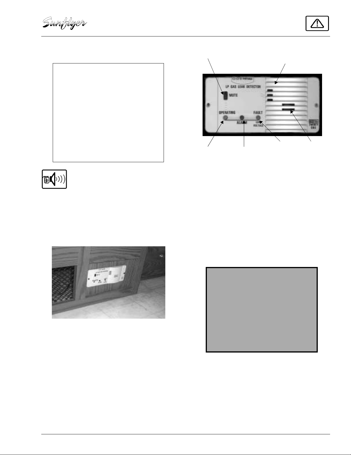
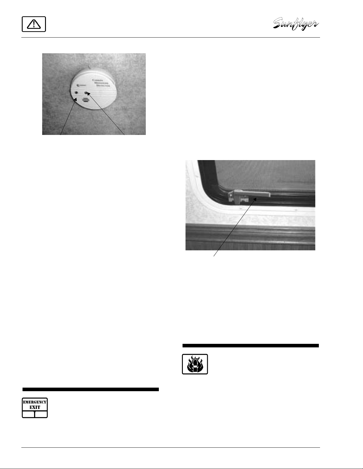
Press to Silence Alarm
Green
(Active)
Red
(Active)
SECTION 1
Gas Sensor
Amber
(Low Batt)
Alarm
Speaker
LP GAS ALARM
Your coach is equipped with an LP gas detector which sounds an alarm if an unsafe amount of
LP gas is present inside the coach. Because LP
gas is heavier than air, the detector is located on
a cabinet face near the floor of the coach.
A green light on the face of the alarm shows
when the unit is active. If the detector senses LP
gas, the alarm will make a loud, pulsating sound
and the red light will come on. Pressing the
“MUTE” button will stop the alarm for 60 seconds. If there is no more detectable LP gas, the
alarm will stay off. If the detector still sense s LP
gas by the end of the 60 second mute mode, the
alarm will sound again.
If The Alarm Sounds
If the alarm sounds, do not touch any electrical
switches. Immediately turn off the main LP tank
valve and all LP appliances, open all windows
and roof vents, and leave the coach until the
alarm stops sounding.
If the alarm keeps sounding at regular intervals, a leak may be present. Contact your dealer
or an LP gas service center to have the problem
corrected before using the LP system again.
WARNING
Never use an open flame to test for
gas leaks. When testing for gas line
leaks with a soapy water solution, DO
NOT use a detergent containing
ammonia or chlorine. These substances may generate a chemical
reaction causing corrosion to gas
lines, resulting in dangerous leak conditions.
Power Connection
The gas alarm is powered by the coach batteries. If the battery cable is disconnected from the
batteries, auxiliary battery switch is shut off, or
the fuse is blown, the alarm will not work. The
LP gas alarm breaker is located on the coach circuit breaker panel shown on page 6-7.
Because the LP gas alarm is connected directly to the auxiliary battery, it is always drawing a
1-3

SECTION 1
SAFETY PRECAUTIONS
small amount of current. Even though this current
draw is slight, it could drain the coach battery
during storage periods of 30 days or longer. We
recommend turning the auxiliary battery switch
off or disconnecting the battery cables from the
auxiliary battery during extended storage periods
to avoid discharge.
If the coach batteries become extremely
drained (8.5 volts or less), the amber Low Voltage/FAULT light on the face of the alarm will
cone on, and in some rare cases the LP alarm may
begin to sound on its own. This condition is not
likely to occur except during storage situations
when coach battery charge is not being restored
by the converter charger or solar charger.
Other Combustible Fumes or Vapors
This alarm is designed to detect the presence
of LP gas, however there are other combustible
fumes or vapors which may be detected by the
sensor. These include: alcohol, liquor, deodorants, colognes, perfumes, wine, adhesives, lacquer, kerosene, gasoline, glues, most all cleaning
agents and the area is closed up. Glues and adhesives may exhaust hydrocarbon vapors for
months after they are applied. The y are easily activated by high temperatures. If you close up an
RV coach on a hot day, the chemicals used in its
construction may be detected for months after the
coach was manufactured.
Further Information
See the manufacturer’s information entitled
“Your LP Gas Detector” in the InfoCase for further instructions on nuisance alarms and care and
testing of the LP gas detector.
do not adapt the plug to connect to a receptacle for which it is not designed.
· Do not attach an extension cord to the utility
power cord.
· Be sure that all electrical appliances to be
used contain 3-prong plugs for proper
grounding.
· Avoid overloading electrical circuits. Replace fuses or circuit breakers with those of
the same size and amperage rating only. Never use a higher rated fuse or breaker.
· Use caution when handling or working near
electrical storage batteries. Always remove
jewelry and wear protective clothing and eye
covering. Avoid creating sparks.
LOADING
· Store or secure all loose items inside the
motor home before traveling. Possible overlooked items such as canned goods or small
appliances on the countertop, cooking pans
on the range, or free-standing furniture items
can become dangerous projectiles during a
sudden stop.
· Be aware of GVWR, GAWR and individual
load limit on each tire or set of duals. (See
“Loading the Motor Home” in Section 4.)
ELECTRICAL
· Careless handling of electrical components
can be fatal. Never touch or use electrical
components or appliances while feet are bare,
while hands are wet, or while standing in
water or on wet ground.
· Improper grounding of the vehicle can cause
personal injury. Do not plug the utility power
cord into an outlet which is not grounded and
1-4
· Never load the motor home in excess of the
gross vehicle weight rating or the gross axle
weight rating for either axle.
MAINTENANCE
· Do not remove the radiator cap while engine
and radiator are still hot. Always check coolant level visually at the see-through coolant
reservoir.

SECTION 1
SAFETY PRECAUTIONS
· Never get beneath a vehicle that is held up by
a jack.
· Do not mix different construction types of
tires on the vehicle such as radial, bias or belted tires, as vehicle handling may be affected.
Replace tires with exact size, type and load
range.
· Do not attempt to start the vehicle by hot
wiring.
FORMALDEHYDE INFORMATION
WARNING
Some components in this vehicle contain formaldehyde based adhesives
which may release formaldehyde
fumes into the air for an unknown
period of time until total dissipation
occurs. Individuals who are allergic
to formaldehyde gas fumes may
experience irritation to eyes, ears,
nose and throat. Reaction in infants
may be more severe. Although long
range effects are not well understood,
testing to date has not revealed any
serious health effects in humans at the
level of emission from these products.
IMPORTANT
To aid in dissipation, ventilate the vehicle by
opening all windows and circulating the air with
a fan.
If your suspect that exhaust fumes are entering
the passenger compartment, have the cause determined and corrected as soon as possible. If you
must drive under these conditions, drive only
with ALL WINDOWS FULLY OPENED.
The best protection against carbon monoxide
entry into the vehicle body is a properly maintained engine exhaust and ventilation system. It
is recommended that the exhaust system and
body be inspected by a qualified motor home service center.
· Each time the vehicle is raised for an oil
change.
· Whenever a change in the sound of the ex-
haust system is noticed.
· Whenever the exhaust system, underbody or
rear of the vehicle is damaged.
To allow proper operation of the vehicle’s
ventilation system, keep front ventilation inlet
grill clear of snow, leaves or other obstructions at
all times. DO NOT OCCUPY A PARKED VEHICLE WITH ENGINE RUNNING FOR AN
EXTENDED PERIOD.
Do not run engine in confined areas, such as a
garage, except to move vehicle in or out of area.
When vehicle is stopped in an UNCONFINED
area with the engine running for any more than a
short period, adjust heating or cooling system to
force outside air into the vehicle as follows:
1. Set fan to medium or high speed and vent
control to air.
2. On vehicles equipped with air conditioning,
set fan to medium or high speed and set control to obtain maximum vent air.
CARBON MONOXIDE
WARNING
WARNING
Avoid inhaling exhaust gases, as they
contain carbon monoxide, which is a
colorless, odorless and poisonous gas.
Rear windows should be closed while driving
to avoid drawing dangerous exhaust gases into
the vehicle.
CARBON MONOXIDE
ALARM
If your coach is equipped with a carbon monoxide (CO) alarm, it will be located on the ceiling
in the bedroom area.
1-5
SECTION 1
SAFETY PRECAUTIONS
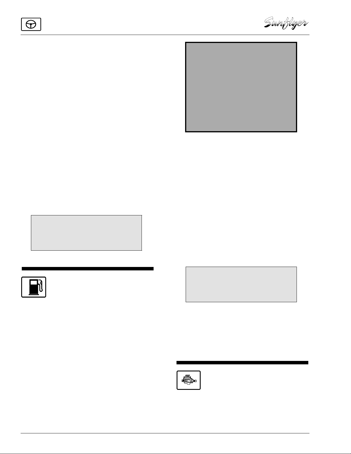
Red Light
(Press to test alarm)
The CO alarm is powered by a 9-volt battery
and contains a sensor that is designed to detect
toxic carbon monoxide gas fumes resulting from
incomplete combustion of fuel. It will detect CO
gas from any combustion source such as the furnace, gas range/oven, water heater, refrigerator,
chassis engine, and electric generator engine.
Yellow Light
(Warning)
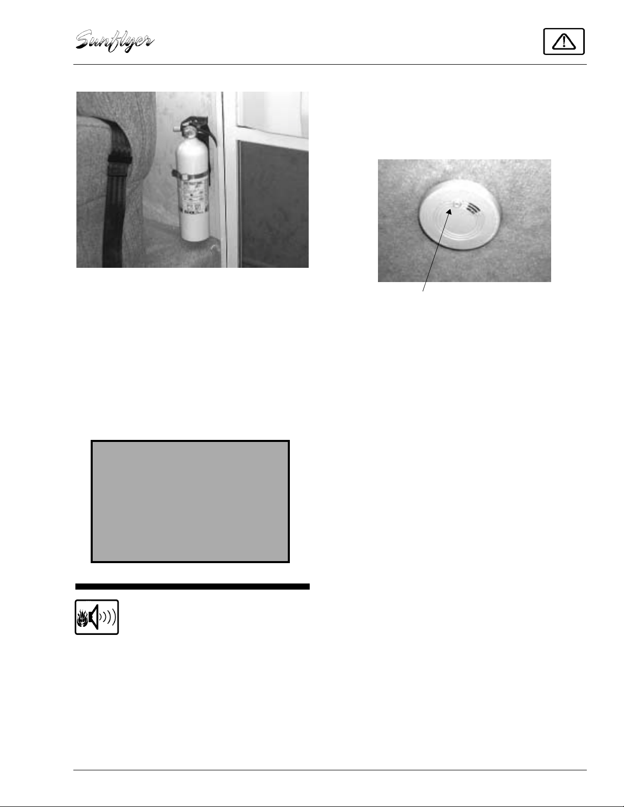
cle which functions as an escape exit in an
emergency situation.
Side Escape Window
The side mounted escape window is secured
by two red safety latches and can be opened by
first releasing these two latches and then pushing
outward on the lower part of the window. Identify which type of emergency exit window is in
your vehicle.
Instructions for removal are also located near
the latches for quick reference and for passengers
who may not be familiar with the exit. Never remove or destroy this label.
Monthly Testing
Press the TEST button on the face of the alarm
periodically (at least monthly) to check the function of the alarm and condition of the battery. If
the alarm begins to beep every few seconds, the
battery may be weak and need replacement.
(Press the TEST button to be sure before replacing the battery. If the alarm sounds, the battery
may still be okay. If the alarm still beeps every
few seconds, check the smoke detector also. The
“low battery” warning beep is similar on many
alarm devices, so the origin of this electronic
sound can be deceiving.)
Further Information
Please read the information provided by the
manufacturer, which is included in your InfoCase. It includes information on precautions, operational testing, and battery/sensor replacement.
EMERGENCY EXITS
Emergency Exit Windows
Lift Both Handles Up
Push Out on Bottom
Using Slider Windows as Emergency
Exits
Most slider windows along the side of the motor home can also be used as emergency exits,
should the need arise. To use the windows as exits, slide the window glass and screen open.
FIRE EXTING UIS H ER
A dry chemical fire extinguisher is located
near the entrance door.
Your motor home is equipped with an emer-
gency exit window in the rear or side of the vehi-
1-6
We recommend that you become thoroughly
familiar with the operating i nstructions displayed
on the side of the fire extinguisher or in the information supplied in your InfoCase.
We also recommend that you inspect the fire
extinguisher for proper charge at least once a
month in accordance with National Fire Protection Association (NFPA) recommendations as
stated on the label.
If the charge is insufficient, the fire extinguisher must be replaced.
WARNING
Do not test the fire extinguisher by
discharging it. Partial discharge can
cause leakage of pressure or contents
which would render the unit inoperative when needed. When using the
fire extinguisher, aim the spray at the
base of the fire.
SECTION 1
SAFETY PRECAUTIONS
once a week during motor home use. To test
the electronics, firmly depress the button. To
test that smoke reaches the sensor, blow
smoke in a careful, fire-safe manner into
your smoke alarm.
Press to
test
2. Your smoke alarm will not work without
power. Never remove the battery to quiet the
alarm. When your smoke alarm “beeps”
about once a minute the battery is weak.
Install a new battery immediate ly. Be sure to
use only batteries specified in manual or on
unit. Test unit after installing a new battery.
3. Clean and vacuum the openings on your
smoke alarm once a month.
4. Do not open the smoke alarm or try to repair
it. For replac emen t inf orm ation see w arra nty
in Owner’s Manual.
5. Smoke alarms have technical limitations and
may not respond in all situations. FIRE PREVENTION is your best safeguard.
SMOKE ALARM
Your motor home is equipped with a smoke
alarm located on the ceiling in the galley area.
This alarm meets U.L. Standard 217 and NFPA
Standard 74 for operation of smoke detection devices.
1. The smoke alarm should be tested for correct
operation each time the vehicle is brought
out of storage, before each trip, and at least
See your InfoCase for further information.
1-7


SECTION 2
DRIVING YOUR MOTORHOME
(See also Safety Precautions, Section 1 of this
manual.)
NOTE: See your Ford or Freightliner chassis
operator's guide for information on
starting the engine, operating the transmission, steering column controls descriptions of instrument gauges and
other chassis related information.
Some items described in this section may
be optional or unavailable on your
coach.
BEFORE ENTERING YOUR
VEHICLE
Before entering your vehicle, there are a few
recommended procedures that will aid in your
driving safety and equipment.
1. Be sure that the windows, mirrors and light
lenses are clean and unobstructed.
2. Make sure all exterior lights operate prop-
erly.
3. Check tires for proper cold inflation pres-
sures.
4. Check wheel lug nuts for tightness.
5. Look beneath the vehicle for noticeable fluid
leakage.
6. Check fluid levels and fill if necessary. This
includes engine oil, transmission fluid, coolant, brake fluid, power steering fluid and
windshield washer solvent.
WARNING
The engine should be shut off unless
specifically required for a certain procedure.
Ford: Transmission must be in P
(Park) and park brake applied while
performing any checks or adjustments.
Freightliner: The transmission must
be in N (Neutral) and park brake
applied while performing any checks
or adjustments.
7. Unhook and store sewer and water supply
hoses.
8. Retract step.
9. Be sure that all of your cargo is secured in
event of a sudden stop or an accident.
10. Check around your vehicle in all directions
to assure that you have proper clearance.
11. Lower TV antenna.
12. Disconnect and store shoreline.
WARNING
Before driving your vehicle, be sure
you have read the entire operator’s
manual and that you understand your
vehicle’s equipment completely and
how to use the equipment safely.
BEFORE DRIVING YOUR
VEHICLE
Before preparing to drive your vehicle, here
are a few recommended procedures that will add
to your driving safety and enjoyment.
1. Be sure that you adjust the interior and exte-
rior rear view mirrors to your driving preference.
2-1
SECTION 2
DRIVING YOUR MOTOR HOME
2. Adjust the driver's seat for proper distance
from foot pedals and steering wheel to allow
for safety and ease in controlling your vehicle.
3. Place front seats in the forward facing position.
4. Be sure to fasten all safety belts to fit you
comfortably, but tight enough to obtain the
full safety of the belts.
5. Make sure all doors are completely shut and
locked. When the doors are shut and locked,
there is less chance of the doors flying open
in event of an accident. It also prevents unintentional opening of doors and keeps
intruders out of your vehicle.
6. Check to see that all gauges are operating
properly.
7. Check the fuel level in the vehicle.
8. Be certain that the fire extinguisher is fully
charged and secure in its mounting bracket.
WARNING
Modern fuel systems may build up
pressure within the tank as the gasoline warms during use or in hot
weather.
Under certain conditions, sudden
release of this pressure when
removing the gasoline cap can spray
gasoline from the fuel fill opening,
causing a possible hazard.
GASOLINE FUEL FILL
Removing the Fuel Cap
When removing the gasoline cap, slowly ro-
tate it only far enough to allow pressure to re-
lease. After any "hissing" sounds stop, continue
removing the cap.
CAUTION
Be sure hood and all compartment
doors are latched securely before
driving vehicle
FUEL INFORMATION
Fuel Tank Capacity:
Ford chassis............................................75 gal.
Freightliner diesel chassis......................90 gal.
FUEL SELECTION
Refer to your chassis operating guide for the
manufacturer's recommendations on proper fuel
selection.
Filling the Tank
Do not overfill the fuel tank. Allow gasoline
to pump into the tank until the auto-shutoff valve
in the fuel pump nozzle stops the flow of fuel, indicating a full tank. This provides a pre-determined vapor space at the top of the tank to allow
for expansion of the gasoline.
CAUTION
Continuing to fill above this level
may cause damage to the fuel/evaporative emission system.
Replacement Fuel Caps
To protect gasoline system from excessive
pressure or vacuum, or from sudden pressure,
replace lost caps with caps of the same design
available from your Winnebago Industries
dealer or a dealership that sells Ford vehicles.
2-2
STARTING AND
STOPPING ENGINE
Refer to your chassis operating guide for the
manufacturer's recommendations on starting and
stopping the engine.

SECTION 2
DRIVING YOUR MOTOR HOME
Brake-Shift Interlock (Ford Chassis)
Ford chassis are equipped with a brake-shift
interlock safety feature. The shift lever cannot
be moved from the Park position unless the ignition is ON and the service brake pedal is pressed.
NOTE: If the brake light fuse is blown, the inter-
lock feature will not work properly and
an alternate method must be used. See
your Ford Owners Guide for detailed instructions on what to do in this situation.
Fuel Pump Shut-Off Switch
(Ford Chassis Only)
Vehicles built on Ford chassis are equipped
with an inertial type switch that shuts off the f uel
pump in the event of collision. This switch must
be manually reset to resume the fuel supply to the
engine.
See your Ford chassis operating guide for location and reset procedures for this switch.
NOTE: It is possible to accidentally trigger the
fuel pump shut-off switch by abruptly
striking an object such as a curb or parking block. If your vehicle exhibits symptoms of running out of fuel immediately
after such an occurrence, the fuel pump
shut-off switch may need to be reset.
Consult your chassis operating guide for
additional information.
allow the fuel to warm up and become fully
liquid again.
During winter time, most truck stops and
reputable filling stations have winter blend
diesel fuels available that are less susceptible to
waxing.
There are also commercially available products, typically called anti-gel additive s, to add to
diesel fuel while filling the tank to inhibit wax
formation in freezing temperatures.
Consult your Freightliner chassis guide or
Cummins engine guide for more information on
fuel requirements and additives.
Filling the Fuel Tank
Diesel fuel, especially #2 grade, can foam up
while being pumped into the tank. Sometimes
this foam can cause the pump nozzle to shut off
before the tank is actua lly full. Allow the foam to
settle then resume f illing at a slower flow rate until the tank is full.
Fuel Tank Capacity: 90 gals. diesel
STARTING AND STOPPING DIESEL
ENGINE
Refer to your Freightliner chassis operating
guide for the manufacturer's recommendations
on starting and stopping the engine.
See also “Engine Block Heater” in this section.
FUEL SELECTION - FREIGHTLINER
DIESEL CHASSIS
Refer to your Freightliner chassis operating
guide for the manufacturer's recommendations
on proper fuel selection.
Winter Fuel Waxing and Anti-Gel Additives
In sub-freezing temperatures, #2 diesel fuel
can form small wax crystals that become trapped
in the fuel filter and block the fuel flow to the
engine, causing it to stall out. At sub-zero temperatures, the fuel can congeal and turn
“slushy”. If this happens, the only remedy is to
have the vehicle towed into a heated facility to
Cold Weather Starting: Please note the following cold weather starting precautions. This label
is also located in appropriate areas of the coach.
Failure to follow these precautions could cause
serious damage to your diesel engine.
2-3

SECTION 2
DRIVING YOUR MOTOR HOME
FREIGHTLINER DIESEL
ENGINE BLOCK HEATER
Your coach is equipped with an engine block
heater to assist starting in freezing temperatures.
The heater is connected to both the shoreline and
the auxiliary generator, so extension cords are not
needed under most circumstances. The power
switch is on the bedroom wall on the driver’s side
of the coach.
To set the parking brake, press the service
brake pedal firmly with your right foot while you
apply the parking brake with your left foot. The
BRAKE warning light will go on as soon as you
start to press the parking brake pedal. The brake
will not prevent the vehicle from moving unless
you push it down firmly and fully. Remove your
foot from the service brake pedal and make sure
there is no vehicle movement.
To release the parking brake, apply the service
brake with your right foot and hold the parking
brake pedal down with your left foot while you
pull the release lever. The release lever is located
above the brake pedal.
Never drive your vehicle with the parking
brake set as this will reduce parking brake effectiveness and cause excessive wear.
Diesel Engine Heater Switch
on driver side bedroom wall
To Use the Engine Heater
With the shoreline cord plugged into a shoreline hookup, turn on the engine heater power
switch on the bedroom wall on the driver’s side
of the coach.
If a shoreline hookup is not available, just start
the auxiliary generator to provide power to the
engine heater.
REMEMBER! Turn the engine heater switch off
after starting the engine. The heater will keep operating for as long as it is supplied with electricity. If the switch is left on, the engine heate r will
come on each time you hook up the shoreline
cord or start the generator.
Optional 16,500 lb. GVWR Chevy Chassis:
This chassis is equipped with an automatically applied parking brake that actuates when
the shift lever is moved to the Park position.
Freightliner Diesel Chassis:
The parking brakes are applied by pulling outward on the large diamond-shaped knob on the
dash to the right of the steering column. Push the
knob in to release the brakes.
Parking Brake Knob
PARKING BRAKES
Ford Chassis:
The parking brake pedal is located to the left
of the foot service brake.
2-4
Use the parking brakes whenever the vehicle
is parked. Never try to drive the vehicle with the
park brake applied. This can cause excessive
wear on the brakes and may damage the transmission.
SECTION 2
DRIVING YOUR MOTOR HOME
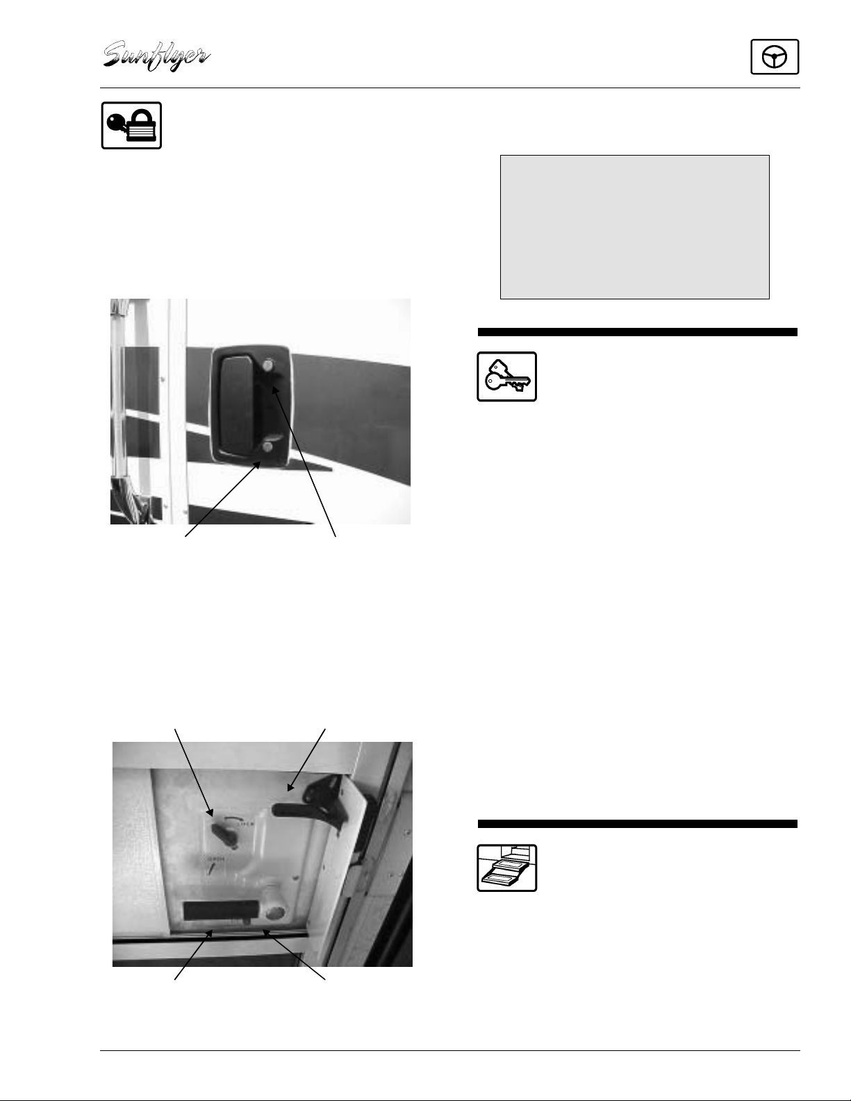
ENTRANCE DOOR LOCK AND
HANDLE
The entrance door may be opened by pulling
the door handle outward. When the door is
locked, neither the inside nor the outside door
handle can be operated. It can be locked and unlocked from the outside of the vehicle by inserting the key into the lock and turning.
Bolt Lock
Door Handle
Lock
To lock the door from inside, rotate the lock
levers as indicated. The deadbolt lock is for added security and should be used as a security night
lock.
Door Handle
Lock
Screen Door
Latch
Lubricate the locks periodically with graphite
to maintain good working condition.
CAUTION
When releasing security night lock,
be sure to retract bolt before opening
door latch to prevent drag on bolt pin.
Instruct all passengers in operation of
this door catch system as well as
emergency exit window.
“KEY ONE” LOCK SYSTEM
Your coach is equipped with the new Key
OneTM lock system. A single key will open every door lock in the entire motor home (except
the security deadbolt lock on the entrance door).
This means you don’t have to sort through a
handful of keys to find the right one for the water
fill door or the luggage doors or the entrance door
or the driver’s door.
The number of the key for your coach is registered in our factory database, so if you ever lose
your keys, any Winnebago Industries dealership
can easily order a new key for you. They are also
equipped with special master keys and can unlock your coach for you if needed.
NOTE: Keys should always be removed when
leaving the vehicle. Since doors can be
locked without keys, make sure they have
been removed from the ignition before
locking the driver's compartment.
Door Lat c h
Handle
Bolt
Lock
ELECTRIC ENTRANCE
STEP
The power switch for the electric entrance step
is located to the left of the main entry door as you
enter the coach.
Automatic Mode (Operates with Door)
With the Power Switch in the On position th e
2-5
SECTION 2
DRIVING YOUR MOTOR HOME
step is in Automatic Mode. This means it will
extend and retract automatically whenever the
door is opened or closed. This is done by means
of a magnetic door switch attached to the lower
hinged edge of the screen door section of the
entrance doors. The steps will extend when the
screen door is opened, and retract when the
screen door is closed. With the power switch in
the Off position the step can be kept in the extended or retracted position as described below.
Stationary Extended Mode
To keep the step in the extended position:
• turn the Power Switch to On,
• open the screen door to extend the step,
• then turn the Power Switch to Off.
The step will now stay extended whether the
door is opened or closed. This position is normally used when parked at a campsite or whenever
people are going to be entering and exiting the
vehicle frequently.
Stationary Retracted Mode
To keep the step in the retracted position:
• turn the Power Switch to On,
• close the screen door to extend the step,
• then turn the Power Switch to Off.
The step will now stay retracted when the
screen door is open or closed. This position is
normally used where an exterior step is not required or to avoid damage to the setp, such as
when parked near a high curb or similar object.
Automatic Retraction Feature
The coach is equipped with a step retraction
feature that retracts the step automatically when
the Ignition Switch key is turned to either the On
or Start position regardless of whether the Step
Power Switch is On or Off. This feature is standard and is installed to prevent injur y or dama ge
which may be caused by an extended step when
the vehicle is moving. An associated feature is
the “Last Out Feature”. This feature extends the
step when the screen door is opened after the
ignition switch has been turned to either the On
or Start position.
WARNING
Do not use steps unless it is fully
extended.
Do Not Stand on step when vehicles
ignition switch is turned to either the
“On” or “Start” position. The step
will automatically retrac t, which may
cause personal injury. Always
remember to retract the step before
moving the vehicle..
For additional information on the step, see the
step manufacturer’s operators manual included in
your Owners InfoCase.
CAUTION
Always remember to retract the
entrance steps before traveling or
moving the vehicle.
LUGGAGE COMPARTMENT DOORS
To ensure that compartment doors have
latched properly, press the bottom edge of the
door with the palms of your hands.
This is more important for smaller and lighter
compartment doors because when the door is
“dropped” closed, the air trapped inside the
compartment may create a cushioning effect that
could prevent door latches from engaging
properly.
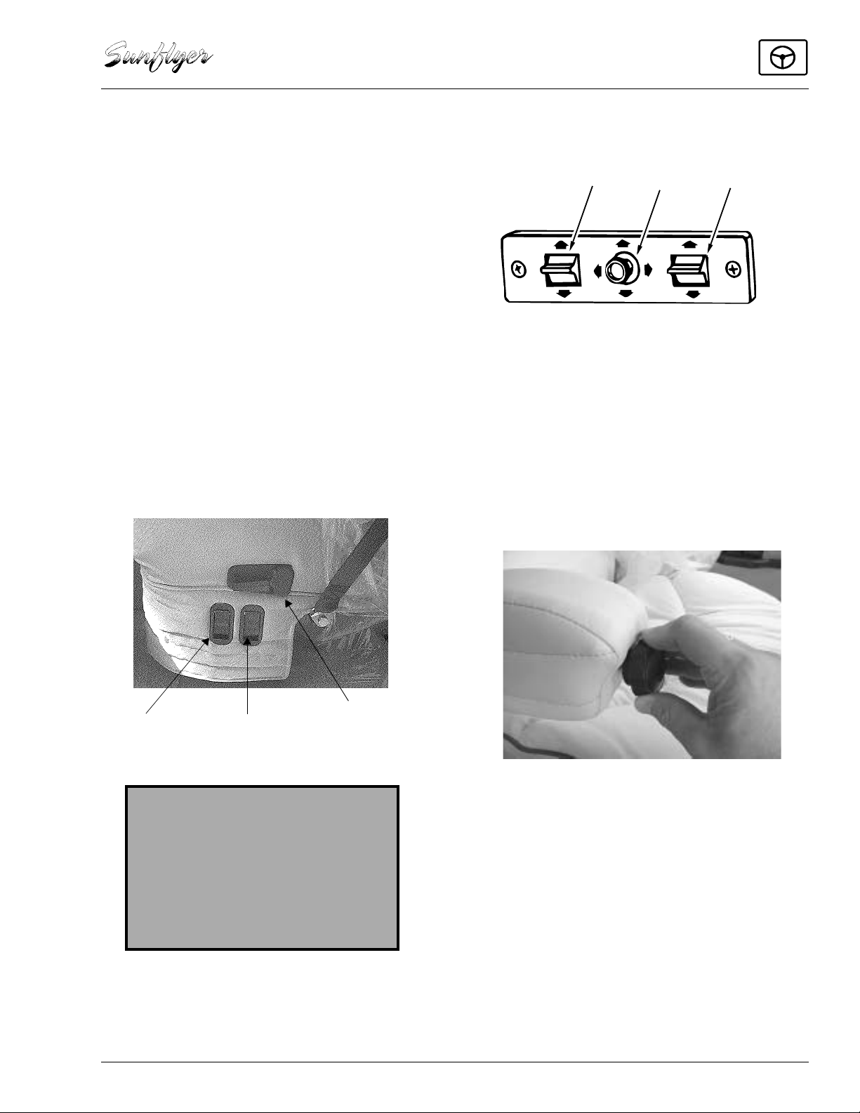
SEATS
The driver and co-pilot seats may be independently adjusted to suit individual preference. To
move the seat forward or backward, press the
slide release button, located on the side of the
seat, and exert slight body pressure in the direction desired.
2-6
The seats may be swiveled to provide easy en-
Main
trance and exit. The swivel feature also allows
the seats on some models to be turned towa rd the
living area for additional seating while the unit is
parked.
To swivel the seats: Press the release button,
located on the side of the seat, and rotate seat.
The seats are designed to lock only when returned to the forward facing position.
NOTE: If your driver seat is equipped with pow-
er seat controls, the swivel release button
is located beneath the seat on the right
side of the seat.
SECTION 2
DRIVING YOUR MOTOR HOME
Front
Up/Down
Seat
Position
Rear
Up/Down
Power Seat Control
To recline the seats: Lift the reclining lever,
lean back to desired incline and release the lever.
To return to the upright position, lift the lever and
lean body forward. Allow the seat to return to the
desired position and release the lever.
Slide
Release
Swivel
Release
Recline
Lever
WARNING
Do not adjust driver’s seat while vehicle is in motion.
ARM REST ADJUSTMENT
The driver and co-pilot seat armrests may be
adjusted to various positions for comfort while
sitting upright or reclined. Turn the knob on the
end of the armrest clockwise (tighten) to raise the
angle or counterclockwise (loosen) to lower the
angle.
Armrest Adjustment Knob
*Tighten to Raise
*Loosen to Lower
After adjusting seat, always use body
pressure to make sure slide and
swivel locking mechanism have
engaged.
6-Way Power Seat Controls
The power seat controls are located on the
lower right hand side of the seat base.
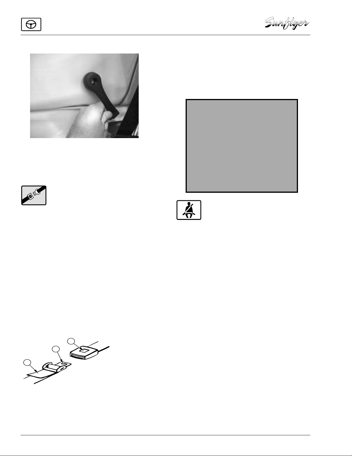
DRIVER SEAT LUMBAR SUPPORT
The driver seat lumbar area can be adjusted to
provide lower back support while driving. The
adjustment lever is at the left side of the driver
seat. Rotate the lever down and to the rear to increase firmness.
2-7
SECTION 2
DRIVING YOUR MOTOR HOME
Lumbar Support Lever
Firm Position
SEAT BELTS
To Fasten: Be sure belt is not twisted. Grasp
each part of the belt assembly and push tongue
into buckle. Adjust to a snug fit by pulling the
loose end away from the tongue.
To Release: Press button in center of buckle and
slide tongue out of buckle.
WARNING
Snug and low belt positions are
essential. This will ensure that the
force exerted by the lap belt in a collision is spread over the strong hip area
and not across the abdomen, which
could result in serious injury.
Only seats equipped with seat belts
are to be occupied while vehicle is in
motion.
Seats intended for occupancy while the vehicle is in motion are equipped with seat belts for
the protection of the driver and passengers.
Lap Belts
The lap belts must be worn as low as possible
and fit snugly across the hip area. Always sit
erect and well back into the seat. To gain full protection of the safety belt, never let more than one
person use the same safety belt at any one time,
and do not let the safety belts become damaged
by pinching them in the doors or in the seat mechanism. After any serious accident, any seat belts
which were in use at the time should be replaced.
3
2
1
1. PULL TO TIGHTEN.
2. TONGUE.
3. PUSH TO RELEASE.
Adjustment: To lengthen belt, turn tongue at a
right angle to belt and pull to desired length. To
shorten, pull loose end of belt.
THREE-POINT LAPSHOULDER BELTS
The driver and co-pilot seat belts in your
coach are equipped with automatic locking retractors that let you easily adjust your seat belt to
the proper length for passenger safety.
Fastening:
· Grasp the belt just behind the tongue using
the hand nearest the door or sidewall. Be sure
the belt is not twisted before fastening.
· Pull the belt smoothly outward from the wall
and across your body, then insert the tongue
into the buckle on the aisle side of the seat until it locks with a positive “click”.
· Feed any excess belt length back toward the
wall so the belt retractor will lock the belt at
the proper length for your body when released.
· The lap belt portion must be worn snug and
low across the pelvic area.
· The shoulder strap portion must be worn di-
agonally across the chest and over the shoulder, but not against the neck.
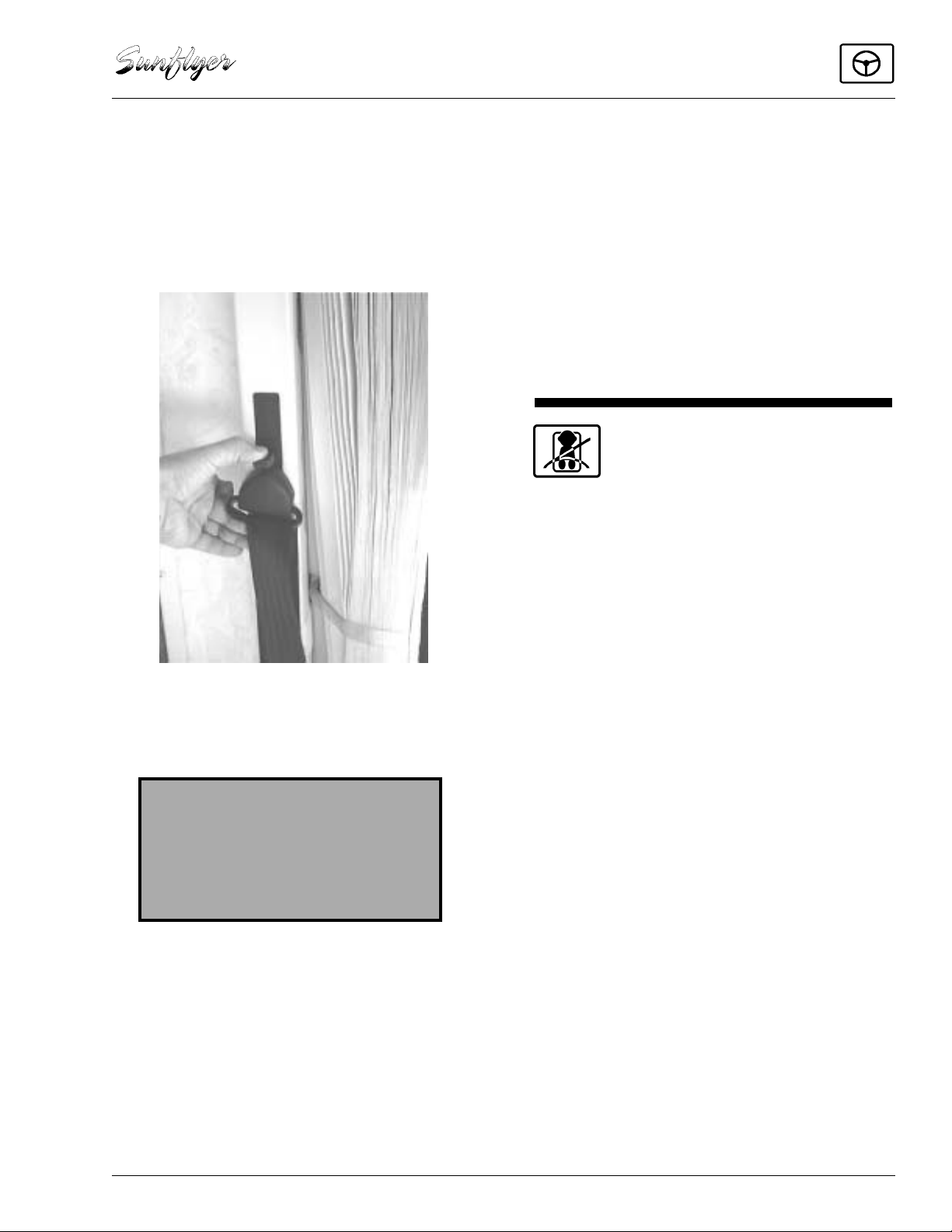
NOTE: The shoulder belt height can be adjusted
to provide the most comfortable position
2-8
SECTION 2
DRIVING YOUR MOTOR HOME
for each individual person’s size. To adjust shoulder belt height, press the lever
down, select the desired position and release the lever. (See following photo.) A
ratcheting mechanism will allow the belt
to be pushed upward but not pulled
downward.
· Seat belts offer optimum protection only
when worn properly on the body and when
the seat is in an upright position.
WARNING
Never wear the shoulder belt in any
position other than as stated above.
Failure to do so could increase the
chance or extent of injury in a collision
Unfastening:
· Press the release button in the buckle.
· Hold onto the tongue when you release it
from the buckle to keep it from re tra cti ng too
rapidly.
Care and Cleaning
· Be careful not to damage the belt webbing
and hardware. Take care not to pinch them in
the seat or doors.
· Inspect the belts and hardware periodically.
Check for cuts, frays, and loose parts. Damaged parts should be replaced. Do not remove
or modify the belt system.
· Keep belts clean and dry. If the belts need
cleaning, use only a mild soap and water solution. Do not use hot water. Do not use abrasive cleaners or bleach. These products may
weaken or damage the belts.
· Replace any belt assembly that was used during a severe impact. Replace the complete assembly even if damage is not apparent.
CHILD RESTRAINTS
All 50 of the United States and the District of
Columbia now require the use of the child/infant
restraint systems for children in vehicles.
A properly installed and secured child restraint system can help reduce the chance or severity of personal injury to a child in an accident
or during a sudden maneuver. Children may be
injured in an accident if they are not seated in a
child restraint which is not properly secured.
A child restraint system is designed to be secured in a vehicle seat by a lap belt or the lap belt
portion of a lap-shoulder belt. According to accident statistics, children are also safer when properly restrained in rear seating positions than in
front seating positions.
When purchasing a child restraint system:
1. Look for the label certifying that it meets all
applicable U.S. Federal Motor Vehicle
Safety Standards (FMVSS) or, in Canada,
requirements of the Children's Car Seats and
Harnesses Regulations (CCSHR).
2. Make sure that it will attach to your vehicle
and restrain your child securely and conveniently so that you are able to install it correctly each time it is used.
3. Be certain that it is appropr iate for the child's
height, weight and development. The
instructions and/or the regulation label
attached to the restraint typically provides
this information.
2-9

SECTION 2
DRIVING YOUR MOTOR HOME
4. Review the instructions for installation and
use of the restraint. Be sure that you understand them fully and can install the restraint
properly and safely in your vehicle.
POWER ELECTRIC MIRRORS
Always adjust mirrors for maximum
rear visibility before driving off. Make sure the
seat is adjusted for proper vehicle control and that
you are sitting back squarely into the seat.
The electric mirrors are adjusted using a
multi-directional switch located on the driver’s
door panel to the left of the steering wheel.
Press to move mirror in indicated direction
Move L or R to select mirror, or center for “neutral”.
The power mirror control switch is intended
for fine adjustment of the mirrors. If you cannot
adjust the mirror properly using the control
switch, the mirror may need a coarse adjustment
by repositioning the mirror head. See the mirror
manufacturer’s instructions in your Owner InfoCase.
Mirror Heat
Switch
Mirror Adjustment
Control
Select the mirror to be adjusted by pushing the
switch in the middle of the control to the right or
left. Then press the arrow buttons as necessary to
obtain the best view.
When mirrors are adjusted to preference,
place the selector switch back in the middle position to cancel power to the buttons. This prevents
accidental misadjustment of mirror settings.
The mirrors also contain heating elements to
defog or de-ice the mirror glass during cold
weather operation. An ON-OFF switch for the
mirror heaters is located near the remote mirror
controls.
More Info
To read more about power mirrors, see the
mirror manufacturer’s information in your Owner InfoCase.
SONY REARVIEW TV
MONITOR SYSTEM - Optional
2-10

If your motor home is equipped with this
optional system, refer to the InfoCase for specific
instructions provided by Sony.
INSTRUMENT PANEL
GAUGES AND CONTROLS
The illustrations on the following page showing switches and features provided by Winnebago Industries.
See your chassis owner's manual for detailed
information on the instrument gauges, steering
column controls, brakes, and other chassis original equipment.
SECTION 2
DRIVING YOUR MOTOR HOME
2-11

SECTION 2
DRIVING YOUR MOTOR HOME
INSTRUMENT PANEL
1. Headlight/Panel Light Switch*
2. Fog Lamp Switch
3. Aux. Start Switch
4. Instrument Cluster*
5. Rear View (Backup) Monitor*
6. Gen Set Switch
7. Radio Power Switch
8. Coach Rear Heater Fan Switch
9. Antenna Check Light
10. Aux. Windshield Fan Switch
11. Cigarette Lighter/12V Socket
12. Radio/Cassette or CD Player
13. Auto Heater/AC Controls
14. Leveling Jack Control Pad & Slideout Switch
2-12
* See your Ford or Freightliner chassis operating guide.
**If not equipped with monitor system, this space contains 6-tape cassette storage caddy.
NOTE: Some equipment or controls shown may be optional or unavailable on your model.
Ford instruments shown for illustration purpose only.

SECTION 2
DRIVING YOUR MOTOR HOME
MULTI-FUNCTION SIGNAL
LEVER
The multi-function signal lever controls the turn signals, high/low beam changing,
windshield washer, wipers and wiper delay, and
the electronic speed control (cruise) on some
models.
See your chassis operating guide for complete
operating information.
HEADLIGHT BEAM CHANGE
AND TURN SIGNALS
Move multi-function lever upward for right
turn signal and downward for left turn signal.
Pull end of handle toward you to switch high
beam to low, or low beam to high.
WINDSHIELD WIPERS AND
WIPER DELAY
See your chassis operating guide for complete
operating information.
Delay: Turn the outer knob pointer to “Delay”.
Turn the center (wash) knob to set the time you
want between wipes, from 1 second (all the way
left) to about 90 seconds (all the way right).
HAZARD WARNING LIGHTS
See chassis manual or "Instrument Panels" in
this section for location of hazard flasher switch.
See also Section 3 for further operating information.
CRUISE CONTROL
The electronic speed control (cruise) allows
you to maintain a steady speed and relieve driving strain while traveling long distances.
See your chassis operator manual for complete instructions and precautions on the cruise
control.
WARNING
Do not operate the cruise control on
icy or extremely wet roads, winding
roads, in heavy traffic, or in any other
traffic situation where a constant
speed cannot be maintained.
WINDSHIELD WASH/WIPE SWITCH
(Freightliner Chassis)
Wash: Press the control knob to pump washer
solution onto the windshield. The wiper will also
begin operating. The wiper will continue for 5
wipes after you release the washer knob.
Center Knob:
Push for Wash
Turn to Adjust
Wiper Delay
Outer Knob:
Turn to Select
Wiper Speed
Wiper: Rotate the outer knob pointer to the desired setting - Delay, Low or Hi.
COMFORT CONTROLS
AUTO AIR CONDITIONER/
HEATER
Controls for the air conditioner, heater, defroster and vent are all combined into one control
panel. Refer to the following instructions for use
of individual controls.
Fan Speed
Control
Temp
Control
Mode
Selector
2-13

SECTION 2
DRIVING YOUR MOTOR HOME
1. Front Heater Fan Switch
2. Temperature Control Knob
3. Mode Selection Knob
Heating
A. For maximum heating
1. Turn the temperature control knob
toward the COOL (blue) zone to the
desired comfort position.
2. Turn the temperature control knob to
WARM (red).
3. Place the fan switch to high (largest dot).
Air Conditioning
A. For maximum cooling.
1. Turn the mode selection knob to MAX
A/C.
2. Turn the temperature control knob all the
way left to the COOL (blue) position.
3. Turn the fan speed switch in to high
(largest dot).
Off
When no heating, cooling or defrosting are
required:
B. For reduced heating:
1. Turn the temperature control knob to the
left to an intermediate setting.
2. Adjust the fan speed for desired volume.
Defrosting
A. For maximum defrosting and defogging:
1. Turn the mode control knob to DEF.
2. Turn the temperature control knob to
WARM (red).
3. Turn the fan switch to high (largest dot).
4. Turn on auxiliary (dash) fans if additional air movement is needed
B. For reduced defrosting:
1. Turn the temperature control knob to the
left to an intermediate setting.
2. Adjust the fan speed for desired volume.
1. Turn the mode selection knob to OFF. This
will shut off the fan and prevent outside air
from entering the unit.
NOTE: The automotive air conditioner is not de-
signed to cool the entire interior of the
motor home, but is intended to cool the
driver's compartment only.
AUX. COACH HEATER
To provide auxiliary heat to the coach area
while driving, turn the coach heater fan switch to
the desired speed. Heat will be distributed
throughout the coach through the floor ducts
(registers).
Ventilation
A. To vent outside air into the vehicle when nei-
ther heating or cooling is required.
1. Turn the mode selection knob to vent.
2. Turn the temperature control knob all the
way to the left to the COOL (blue).
3. Adjust the fan speed for desired volume.
2-14
Coach
Heater
Switch

STEREO SOUND SYSTEM
Radio Cassette Player (Standard) or
Radio Compact Disc Player (Optional)
Your coach may be equipped with a standard
AM/FM stereo radio cassette player or an
optional AM/FM stereo radio/CD player. Both of
these systems provide high quality stereo sound
for your listening enjoyment while traveling or
parked.
Refer to the Sony radio information supplied
in your InfoCase for detailed operating and care
instructions.
SECTION 2
DRIVING YOUR MOTOR HOME
Radio Power Switch
The radio power switch lets you connect the
dash radio to the coach batteries with the ignition
switch turned off for listening while parked. This
prevents accidental draining of the chassis (starting) battery during prolonged operation of the
radio.
Deluxe Sound System (Optional)
Your coach may be optionally equipped with
a deluxe sound system featuring special highoutput cube speakers and subwoofers to enhance
your listening enjoyment.
Place the Radio Power Switch in AUX position and the Ignition Switch in ACC position.
A speaker selector switch in the front overhead cabinet (video center) lets you switch the
deluxe speakers to your desired sound source,
whether the dash radio or the TV and VCR for
theater surround sound listening.
SPEAKER SOURCE
SELECT SWITCH
RADIO
TV
SONY COMPACT DISC
CHANGER - Optional
The remote CD changer is located out of sight
in the overhead cabinet above the driver’s compartment. The changer cartridge holds up to 10
compact discs for several hours of listening enjoyment.
The CD Changer is operated with a hand-held
remote control unit, which transmits through the
CD changer display face in the dash. The remote
control unit is included in your Owner InfoCase.
See the Sony Compact Disc Changer System operating guide in your InfoCase for complete operating instructions and basic troubleshooting.
2-15

SECTION 2
TO
CB Radio Wiring
DRIVING YOUR MOTOR HOME
AUX. START SWITCH
This switch can be used to provide emergency
starting power from the house batteries if the
automotive battery is dead.
Always leave this switch ON except during
long storage periods (a month or more).
CB RADIO WIRING
(Optional)
If engine battery is dead, press while turning ignition key for emergency starting power
AUXILIARY BATTERY (Aux. Batt)
SWITCH
The AUX BATT switch is located near the entrance steps. It disconnects the auxiliary (house)
batteries from the 12-volt system of your coach to
avoid long-term battery drain by electrical items
that are hooked directly to the house batteries.
If your coach is pre-wired for CB radio installation, the wires are located beneath the dash to
the left of the steering wheel.
Look for a pair of wires, purple (+) and green
(-), with connectors and flag labels, suspended
from the wiring harness.
Be sure to read the wire labels before installing a CB radio. The labels contain important information and cautions.
CB RADIO
TO
CB RADIO WIRING
CB POWER PROVISION
CB ANTENNA
CABLE
CB POWER PROVISION
Purple
RED + 12 V
Green
BLACK GROUND
Coax
COAX ANTENNA
(SEE REVERSE ALSO)
(See Reverse Also)
+12 V
Ground
Antenna
WIRE ASM-IP,MAIN
LABEL
2-16

SECTION 2
DRIVING YOUR MOTOR HOME
SWR ADJUSTMENT
To adjust CB antenna SWR (standing wave
ratio), turn the adjusting ring of the antenna to
achieve the lowest SWR reading. This procedure
will help optimize transmitting and receiving capabilities of the radio system.
See the HWH Operator Manual in your Owner
InfoCase for complete operating instructions. It
also contains additional precautions, technical information, and instructions for manual operation
if automatic functions fail.
The leveling system control panel is located
on the lower left dash panel.
Hydraulic Leveling System
Control Panel
CAUTION
The CB radio could become damaged
if CB antenna SWR is not adjusted
before operating CB radio.
COACH LEVELING SYSTEMS
Your coach is equipped with a HWH®
hydraulic leveling system.
This leveling system is designed to diminish
problems in selecting a parking site, making “set
up” easier and faster for you.
NOTE: When parking at an uneven site, always
park the front of the motor home to the
downhill side. This allows you to level by
raising the front end rather than the rear.
Since only the rear wheels are locked
while in PARK, raising the rear wheels
off the ground could allow the vehicle to
roll off the jacks.
CAUTION
Do not try to drive vehicle unless
‘TRAVEL’ light is glowing with ignition switch on.
Do not try to drive the vehicle until
the air suspension system has built up
sufficient pressure if you have used
the coach leveling system or have
used the DUMP button to manually
exhaust the air suspension system.
2-17

SECTION 2
li
k
Slid
DRIVING YOUR MOTOR HOME
WARNING
Keep all people clear of the coach
while the leveling system is operating.
Do not use leveling jacks to support
vehicle for service or tire changing.
ing light will alert you when the system is in the
Park & Level
TM
(Manual) mode.
CAUTION
Do not drive the vehicle with the
Auto/Manual position. Damage to
suspension components could result.
NOTE: If one of the leveling jacks should fail to
retract, it can be manually retracted by
opening a valve on the hydraulic pump.
The jacks are spring loaded to retract
when hydraulic line pressure is relieved.
See the HWH Operator’s Manual included in your InfoCase for specific instructions on which valve to open and what
precautions to follow. The hydraulic
pump is mounted between the front chassis frame extensions just behind the front
bumper of the coach.
Leve
ng Jac
Valves
eout Room
Valves
NOTE: Automatic leveling is deactivated when
the ignition is switched off, so the coach
may appear “jacked up” in the rear under certain circumstances. This is not a
malfunction and should be no cause for
alarm. When the vehicle is restarted, the
automatic leveling system will immediately correct this situation.
Park & LevelTM System
The Park & Level system incorporates electronic air distribution controls for vehicle leveling purposes. It allows air spring pressure to be
manually adjusted up-and-down or side-to-side
to simulate the function of a hydraulic leveling
system. This provides the vehicle owner with a
reasonable degree of flexibility in parking/camping site selection.
Park & LevelTM Controls
The Park & Level control panel is located at
the lower left-hand side of the dash. It contains 3
rocker switches, a compressor indicator light;
and a manual mode warning light.
Leveling/Slideout System Hydraulic Pump
(top view from hood opening)
JET AIR RIDETM PARK & LEVELTM
SYSTEM - Optional
(Not available on Freightliner Chassis)
Operating Instructions
Normal Driving Mode
The mode switch should be placed in the
“Auto” position before driving off. A red warn-
2-18
Leveling
Press the mode switch to “Manual”. A red
warning light will illuminate to indicate that the
leveling feature is activated. Level the vehicle by
operating the level switches.
· When raising the rear of the vehicle, opera te
both springs at the same time to provide max-
imum lifting power.
· When parked on a side hill, raise both springs
as mentioned above, then lower the spring on
the “uphill” side until the vehicle is level.

· When you’re ready to drive off, switch the
mode to “Automatic” and wait until the
springs automatically adjust for road travel.
NOTE: The air bags will inflate and deflate
slightly about 5 to 8 times until the coach
is leveled.
Compressor Light
The green indicator light labeled “Compres-
sor On” will illuminate only while the compressor is operating. When air pressure depletes to a
preset minimum amount, the compressor will operate until maximum pressure is restored.
It is normal for the com pre ssor to oper ate pe-
riodically while driving to maintain air pressure
in the system. It will also operate for a few minutes after starting the vehicle and switching the
Auto/Manual switch back to “Auto” (when Park
& LevelTM has been in use) to restore air pressure
released during leveling.
SECTION 2
DRIVING YOUR MOTOR HOME
Automotive Circuit Breakers & Fuses
(Beneath left side of dash)
Always replace fuse with one of equal size
and amperage rating.
Air Suspension Warning Light
CAUTION
The rear air suspension warning light,
located on the lower instrument pan el
to the right of the steering column,
will illuminate if a failure should
occur in the tax axle/rear suspension
system. If this should occur while
driving, the vehicle may be carefully
driven to the nearest Winnebago or
Itasca dealer or a qualified truck air
suspension service center. Although
this condition does not totally disable
the vehicle, it will cause less than satisfactory ride characteristics and
should be serviced as soon as possible
to restore proper performance.
System Fuse
If the Jet Air Ride system fails to operate,
check the 30A plug-in fuse located on automotive circuit breaker/fuse panel on the firewall
below the left side of t he dash. Tur n twist lock t o
the left to remove protective cover. Pull cover
outward and up to remove.
Periodic Maintenance
See Section 9.
SLIDEOUT ROOM EXTENSION
CAUTION
Release slideout room travel latches
before attempting to extend slideout
room. Fasten travel latches before
driving vehicle. See instructions
below.
The slideout room extension provides a spacious living area at the push of a button. The
slideout room is extended and retracted using a
hydraulic mechanism with an electronic control
system. The front slideout control switch is located on the lower left dash area.
Travel Straps
The travel straps must be released before
attempting to extend the room or damage to the
coach will result.
2-19

SECTION 2
DRIVING YOUR MOTOR HOME
The travel straps are designed to help keep
the room extension secured against the coach
sidewall to maintain an effective weather seal
while the vehicle is in motion. They are not
designed to withstand the force exerted by the
hydraulic extension mechanism and will not
prevent accidental extension of the room.
The travel latches are located near the floor at
the front and rear ends of the slideout room.
To Release Straps:
· Pull the strap buckle outward and up to
release tension on strap.
· Pull a short length of the excess strap back
through the buckle to provide sufficient
slack.
· Unhook the strap end pegs from the mooring
brackets on the floor and wall edge. Store
straps in location of your choice. (Under the
couch is one choice.)
.
To Fasten Straps:
· Hook the strap end pegs into the mooring
brackets.
· Flip buckle downward and press toward strap
until it “snaps” snugly into place against the
strap.
· If a strap is loose or too tight after closing the
buckle, release the buckle and pull the loose
end of the strap in or out to adjust tension as
needed. Then reclose the buckle.
NOTE: If latches become loose and will not stay
fastened, see your dealer for proper adjustment.
WARNING
Keep all persons clear of the slideout
room and moving parts while extending or retracting. Do not occupy the
slideout room while it is being
extended or retracted.
To Extend SlideOut Living Room or Bedroom:
· Level the coach.
· Set the Parking Brake.
· Release travel straps.
· Press slideout switch and hold until room is
fully extended, then release switch.
2-20

SECTION 2
DRIVING YOUR MOTOR HOME
Before Retracting Slideout Room
If it has rained recently before you retract the
slideout room, we recommend using the hydraulic leveling system to lean the coach and drain off
any excess water possibly remaining on the roof
before retracting. Lean the coach slightly to the
left (driver’s side) as shown by raising both right
side jacks to let excess wat er flow away from the
rooftop weatherseal and toward the outside of the
slideout roof.
roll in the patio side awning. This will protect the
slideout room awning from possible wind damage.
If Slideout Room Will Not Operate
(Troubleshooting)
· The chassis battery may be low on charge.
Press the Aux. Start switch on the dash to the
momentary (MOM) position while pressing
the slideout control switch. This moment arily
connects the coach batteries to assist in retracting the room.
· One of the fuses may be blown. Fuses are located on the interior firewall beneath the
dash, beneath the instrument panel dash pod,
and inside the leveling control pad housing.
· If the batteries and fuses are okay, there may
be a failure in the hydraulic system or electrical system. See “Manual Retracting Instructions” for help.
To Retract Slideout Room:
CAUTION
Although there is an awning over the
roof of the slideout room, there is a
possibility of debris getting onto the
roof. Because the slideout roof is
drawn into the interior of the coach
when retracted, be sure there is no
debris, such as excessive dirt, tree
seeds, twigs, leaves, etc. on the roof
before retracting.
· Remove all items from the coach living room
floor. Turn leveling system on to provide
power to the slideout control switch.
· Press slideout switch and hold until room is
fully retracted, then release the switch.
High Wind Precaution
We remind you to be aware of high winds
while the room is extended because of the effect
they can have on the roof awning. It is a good
idea to retract the room any time high wind conditions exist that would also make it necessary to
Front Slideout Room Extension
Emergency Crank-In Procedure (Use only when room will not retract using
control switch)
If a failure occurs in the slideout electrical or
hydraulic systems, and the room will not retract
using the control switch, you can manually crank
the room in using an emergency winch system
described below. The winch is generally stored
beneath the dinette seat or in a cargo compartment on the passenger side of the coach.
Step 1 - Relieve Hydraulic Line Pressure
· Open the hydraulic pump valves to release
hydraulic line pressure and let fluid bypass
into the fluid reservoir. The pump is located
beneath the coach on a bracket mounted to
the coach frame behind the front bumper of
the vehicle. The valves can be reached best
by lying on your back and reaching up be-
tween the mounting brackets, or reaching
down through the hood opening.
2-21

SECTION 2
N
DRIVING YOUR MOTOR HOME
Leveling Jack Valves
Hydraulic Pump - Slideout/Leveling Systems
(top view from hood opening)
Slideout Valves
Use provided nut driver tool to turn nut
counterclockwise until fully open. (*See
note)
Hydraulic Pump Relief Valve Type-2
NOTE: Your coach may be equipped with one of
two types of hydraulic relief valves as
shown. Type 1 has a T-handle that can be
turned by hand. Type 2 has a small nut
that requires you to use a T-handled nut
driver tool which is provided in your
Stop engine, place transmission in
park position and apply parking brak e
before lying beneath vehicle for this
procedure.
WARNING
InfoCase. See the HWH Operator’s
Manual included in your InfoCase for
specific instructions on which valves to
open for front or rear slideout rooms and
what additional precautions to follow.
· Open the slideout T-handle valves on the
driver side end of the pump only. Turn T-handles counter-clockwise to open.
DO NOT OPEN ANY OF THE LEVELING
JACK VALVES ON THE RESERVOIR
Turn T-handle counter-clockwise until fully open. (*See
ote)
END OF THE PUMP.
*NOTE:The T-handles may turn easily at first
but will become more difficult to turn as
internal springs are compressed. Be sure
to open both valves completely (about 6
turns of each T-handle).
2-22
Step 2 - Attach Winch and Crank Room
Inward
· Remove the register from the floor heat duct
and anchor the winch in the floor. Insert the
winch retainer bracket into the duct cutout in
the floor as shown.
Hydraulic Pump Relief Valve Type-1

DUCT SPACE
WINCH
FLOOR
STRAP
TO COUCH
TUBE BRACKET
TO SLIDEOUT
ROOM
HEAT
REGISTER
NOTE: Be sure the bracket extensions face away
from the slideout room as shown for
proper support while cranking.
· Insert the winch strap hook into the sewn loop
end of the strap beneath the couch.
· Be sure the winch ratchet pawl is in the locking position (against the gear teeth) before
cranking.
· Crank the winch handle clockwise slowly, a
few “clicks” at a time, until the room is fully
retracted. Allow about 10 minutes to crank
room in fully.
NOTE: Attempting to crank the room in too
quickly will raise pressure in the hydraulic fluid lines and make cranking more
difficult.
SECTION 2
DRIVING YOUR MOTOR HOME
· See your dealer for service of the room extension system before using again.
Further Information
See the HWH Hydraulic Room Extension op-
erating guide included in your InfoCase for further instructions and troubleshooting
information.
Bedroom Slideout Emergency
Retraction
In the unlikely event that your bedroom slide-
out fails to retract using the power switch, check
for obvious causes first, such as low charge on
the house batteries, or a burned out fuse on the
chassis fuse block. (See “Troubleshooting” on
page 2-21.)
NOTE: Check fuses #16 Step Alarm and #24 Ra-
dio/Acc. There is also a fuse on the back
of the HWH leveling system control pad,
which must be unfastened from the driver
door to inspect.
If an apparant cause is not found, call the
number on your Winnebago Industries Premium
Roadside Assistance card. They will dispatch a
service vehicle to your location to push the room
extension in so the coach may be driven to your
dealer for service of the slideout control system.
· Unhook the winch and return the winch and
straps to storage locations. Release the strap
by putting slight pressure clockwise on the
crank handle, then moving the ratchet pawl to
the free-wheel position (away from gear
teeth).
Step 3 - Secure Travel Straps and Close
Hydraulic Line Valves
· Fasten the slideout room Travel Straps as
shown on page 2-20.
· Close the hydraulic pump valve T-handles
completely.
NOTE: Close the valves snugly, but do not over-
tighten. Overtightening may cause internal damage to the valves.
NOTE: The following information may be needed
by the service operator to prepare the
bedroom slideout for the “push-in” procedure.
Bedroom Slideout
Emergency ‘Push-In” Procedure
• Open the two hydraulic line valves on the
inboard side of the pump to relieve hydraulic
line pressure. (See Step 1 under “Slide-Out
Room Emergency Crank-In” on previous
page.)
• DO NOT OPEN THE FOUR VALVES ON
THE OUTBOARD SIDE OF THE PUMP.
These regulate the coach leveling jacks.
• Apply a steady inward pressure of approximately 150 lbs. to the exterior sidewall of the
2-23

SECTION 2
DRIVING YOUR MOTOR HOME
slideout room to push the room in toward the
coach until it is snug against the main coach
sidewall.
• NOTE: Use some type of rigid, padded
material to protect the sidewall from punctures, dents or other damage to the finish
from any device or equipment used to press
the sidewall in.
• Pressure must be applied evenly to avoid
binding of the hydraulic mechanism. It may
take about 10 minutes to press the room
extension inward completely.
• When the room is snug against the coach
wall, close the hydraulic line valves to prevent “creep out” during transit.
• See an authorized Winnebago Industries
dealer for service of the slideout control system.
2-24

SECTION 3
b
IN CASE OF DRIVING EMERGENCY
HAZARD WARNING
FLASHER
The hazard warning flasher provides additional safety when the vehicle must be stopped on the
side of the roadway and presents a possible hazard to other motorists. When the flasher is on, it
serves as a warning to the other drivers to approach and overtake your vehicle with caution.
WARNING
Operating the hazard warning flasher
system while moving on the highway
is illegal.
The front and rear turn signals will flash intermittently when the flashers are in operation.
When it is necessary to leave the vehicle, the
flasher system will continue to operate with the
ignition key removed.
See your Ford or Freightliner chassis operator’s guide for information on operating the hazard warning flashers.
The spare tire is mounted on a swing-down
frame assembly beneath the rear of the vehicle.
WARNING
When attempting to remove a spare
tire carrier assembly fr om its i nstal le d
position, do not place any part of your
body underneath the carrier. The
assembly weighs approximately 200
lbs. and, should it fall unexpectedly,
bodily injury may result.
IF YOU GET A FLAT TIRE
In case of sudden tire failure, avoid heavy
brake application. Gradually decrease speed.
Hold steering wheel firmly and move slowly to a
safe, off-road place. Park on a level spot, turn off
the ignition, and turn on the hazard warning
flasher system.
SPARE TIRE STORAGE
Because of the size and weight of this vehicle
and its tires, and the possible complications involved in tire changing, we strongly advise obtaining professional road service to change a flat
tire whenever possible. However, if an emergency situation requires you to change the tire yourself, please exercise extreme caution and read all
tire changing information, both in this manual
and in the chassis manufacturer’s operation
guide.
1. Remove
Bolts from both
rear corners of
carrier
*When the retainer straps are unfastened and pulled back
the tire assembly is free to drop to the ground. Use a suitable hydraulic jack assembly or have an assistant use a
lock-and-lever device to help lower the tire assembly to
the ground to avoid injury.
2. Pull Retainer
Straps Back (2) to
drop* Carrier
Frame
3. Remove
center bolt to
extract spare
tire
NOTE: Freightliner Diesel Chassis: Because of
the size and weight of this vehicle and the
possible complications involved in tire
changing, this chassis is not supplied
with a spare tire. If you experience a tire
related road emergency, call the number
on your Winnebago Industries Premium
Roadside Assistance card. A tire road
service unit will be quickly dispatched to
your location to service your tire on the
spot. A qualified tire road service center
3-1

SECTION 3
IN CASE OF DRIVING EMERGENCY
has the necessary equipment and expertise to handle road tire emergencies
quickly and safely.
MOTOR HOME JACKING AND
TIRE CHANGING
WARNING
We advise you to obtain qualified
road service whenever possible. Do
not try to change a tire yourself
except under emergency conditions,
and only by closely following instructions in this manual and the chassis
operating guide.
If you do satisfactorily complete an
emergency tire change, we recommend that you have the wheel nuts
checked and properly torque tightened by qualified service personnel as
soon as possible.
After a wheel has been properly
torqued and inspected by qualified
service personnel, it should be
rechecked after traveling 100 miles,
then again at each oil change.
NOTE: The jack referred to in the following in-
structions is not supplied with the vehicle. You can obtain one from your dealer.
A jack is designed for use as a tool for changing tires only, not for use as a leveling device or
as a support when servicing.
WARNING
Tire change procedures should be
used in emergency situations only.
The operator is advised to obtain
qualified road service when possible.
3. Turn on hazard warning flasher.
4. Block both front and back of tire on opposite
side of vehicle from wheel to be removed.
5. On soft ground, use a board or other material
under jack as a firm base to ensure that the
jack will not shift.
JACKING POINTS ON VEHICLE
Ford or Freightliner: See your chassis manual
for specified jacking points.
FRONT WHEEL
Before trying to remove the front wheel, observe the above safety precautions, then follow
the procedure below:
1. Place jack under jacking point specified by
chassis manufacturer. See Jacking Points
above. Position jack so it may be operated
without placing your body beneath vehicle.
2. Screw jack extension pad out (up) until it
touches jacking point surface.
3. Begin jacking until jack is firmly positioned
and just begins to bear weight, but do not lift
tire off the ground.
4. “Crack” wheel nuts loose with lug wrench,
but do not unscrew nuts yet.
5. Resume jacking until wheel is free of
ground.
6. Remove wheel nuts and wheel; put spare
wheel in place.
7. Install wheel nuts and tighten as much as
possible with wheel and tire off the ground.
8. Lower tire until tire just contacts the ground.
Tighten nuts with lug wrench in sequence
recommended by chassis manufacturer.
9. Finish lowering jack, then remove jack and
blocks.
SAFETY PRECAUTIONS
Before trying to change either the front or rear
tires, follow these precautions:
1. Park vehicle on level surface only.
2. Turn off engine and set parking brake.
3-2

WARNING
Upon satisfactory completion of
emergency tire change, it is highly
recommended that wheel nuts be
properly torqued and inspected by
qualified service personnel as soon as
possible.
DUAL REAR WHEELS
Before trying to remove the rear wheel, follow
safety precautions in the beginning of the motor
home jacking procedures. Then follow the procedure below:
1. Place jack under jacking point specified by
chassis manufacturer. See Jacking Points on
previous page. Position jack so it may be
operated without placing your body beneath
vehicle.
2. Screw jack extension pad out (up) until it
touches jacking point surface.
3. Begin jacking until jack is firmly positioned
and just begins to bear weight, but do not li ft
tire off the ground.
4. “Crack” wheel nuts loose with lug wrench,
but do not unscrew nuts yet.
5. Resume jacking until wheel and tire are free
of ground.
WARNING
DO NOT crawl under the vehicle
when it is supported by a jack.
SECTION 3
IN CASE OF DRIVING EMERGENCY
7. Mount spare wheel on studs and replace
wheel nuts. Refer to your chassis operating
guide for wheel nut torque and tightening
sequence.
WHEEL NUTS
To properly seat the wheel nuts and to eliminate the possibility of the wheel nuts becoming
loosened while driving, they should be tightened
at frequent intervals to the torque specified in
your chassis operating guide. This is especially
important after the first 100, 1,000 and 6,000
miles of operation after replacement of a wheel or
wheel nuts.
RECOVERY TOWING
When calling a professional towing service,
we recommend that you advise them of your
coach length and approximate front axle weight.
This will allow the towing operator to determine
the proper towing equipment to use. (This information is found on the vehicle certification label
located to the left of the steering wheel.)
We recommend that you ask for an underlift
(wheel lift or frame lift) type towing assembly for
safe towing.
Winnebago Industries does not assume responsibility for damage incurred while towing
this vehicle.
6. Remove wheel nuts and wheel.
NOTE: When installing the outer dual wheel and
tire assembly, rotate the outer dual wheel
so valve stems are accessible but not
touching one another. In some cases this
means that the inner and outer valve
stems should be in separate wheel cutout
locations
NOTE: When installing or tightening dual
wheels, both wheels on the same side
must be off the ground (not resting on the
inner dual). This minimizes the possibility of loose wheels after correct mounting
torque is applied.
NOTE: Consult the chassis operating guide for
any additional towing instructions or
precautions provided by the chassis
manufacturer.
CAUTION
Do not lift on bumper. Damage will
result to front end body parts.
3-3

SECTION 3
IN CASE OF DRIVING EMERGENCY
WARNING
Stay out from beneath the motor
home while it is suspended by the
towing assembly unless the vehicle is
adequately supported by safety
stands. Do not allow passengers to
occupy a towed vehicle.
NOTE: Know and obey all state and local towing
regulations. Tow at reduced speed.
JUMP STARTING
WARNING
Automotive batteries produce caustic
acid, explosive gases, and electrical
current which may cause burns. It is
important that the instructions below
are followed exactly, or personal
injury (particularly to eyes) or property damage may result due to battery
explosion, battery acid, or electrical
(short circuit) burns.
• NEVER smoke near the battery or
expose it to open flame or electrical sparks.
• Wear eye protection or shield
your eyes while working near battery, in case an explosion does
occur. NEVER lean over a battery.
• Do not allow battery fluid to contact eyes, skin, clothing, or
painted surfaces. Immediately
flush any contacted area with
water. If eyes are affected, seek
medical help after flushing.
• Remove all metal jewelry to
lessen the risk of a short circuit
occurring.
CONNECTING JUMPER
CABLES
volt battery and negative ground compatible
with your vehicle’s electrical system.
2. Position the vehicle with the good battery so
that the jumper cables will reach, but do not
allow the vehicles to touch.
3. Turn off all electrical accessories, motors,
and lights except those needed for safety or
to light up the work area. Place automatic
transmission in P (Park). Be sure parking
brakes are engaged in both vehicles.
4. If the weak battery has filler caps, make sure
the electrolyte is at proper level. Add distilled water if fluid is low . If electrolyte is not
visible or appears to be frozen - do not
attempt jump starting! A battery may rupture or explode if the electrolyte is frozen or
not filled to the proper level.
5. Connect one end of the positive “+” (red)
jumper cable to the positive “+” terminal of
the weak battery. Connect the other end to
the positive “+” terminal of the charged battery.
6. Connect one end of the negative “-” (black)
jumper cable to the negative “-” terminal of
the charged battery.
7. Finally, connect the remaining end of the
negative “-” (black) cable to a solid, metal
grounded location on the engine of the vehicle with the weak battery, at a point at least
18 inches from the battery. Do not connect to
any moving parts. THE MAIN SAFETY
PRECAUTION IS TO MAKE THE FINAL
GROUND CONNECTION ON THE
ENGINE AT A SAFE DISTANCE FROM
THE BATTERY. THIS HELPS TO
REDUCE THE CHANCE OF EXPLOSION DUE TO SPARKS.
8. Start the engine of the vehicle with the
charged battery, and allow it to run for a few
minutes at moderate r.p.m. Then start the
engine of the vehicle with the discharged
battery.
9. Reverse the above sequence EXACTLY
when removing the jumper cables. Start by
removing the cable from the ground location
on the engine first, then continue in reverse
sequence.
1. Make sure that the other vehicle has a 12-
3-4

WARNING
Do not attempt to push-start this vehicle. Damage to the transmission or
other parts of the vehicle could occur.
CONNECTING A BATTERY
CHARGER
To connect a battery charger, first make sure
the engine is switched off. Disconnect the positive (+) lead from the battery. Never disconnect
the battery while the engine is running or alternator damage could result.
Connect the positive “+” (red) lead of the
charger to the positive “+” terminal on the
battery. Next, connect the negative “-” (black)
lead of the charger to a suitable ground. Finally,
plug in or switch on the charger.
To disconnect the charger after charging, unplug the charger from the electrical outlets, remove the charger leads from the vehicle, and
reconnect the vehicle leads to the battery.
ENGINE OVERHEAT
WARNING
Operating a vehicle under a severe
overheating condition can result in
damage to the vehicle and may result
in personal injury.
An engine will overheat if the coolant is low
or there is a loss of coolant because of one or
more of the following:
- a leak in the cooling system
- a hose failure
- a drive belt breaking
- water pump failure
SECTION 3
IN CASE OF DRIVING EMERGENCY
If the TEMP indicator on the instrument panel
shows a rise in engine coolant temperature while
driving, take the following steps to attempt to
lower the overheating condition:
- If you are using the automotive air condition-
er, turn it off.
- If you are stopped in traffic, shift the trans-
mission into P (Park), and engage parking
brake.
If the temperature does not drop within a
minute or two:
- Pull the vehicle over to the roadside as soon
as it is safe to do so.
- Place the transmission in P (Park) and press
the accelerator to increase engine speed
(r.p.m.’s) to twice that of normal idle speed,
and hold it there for approximately two or
three minutes.
- If engine temperature does not go down, turn
the engine off and wait until the engine has
cooled before attempting to open the hood.
If you see or hear steam escaping from the radiator or the engine compartment or have any
other reason to suspect an extreme engine overheating condition, pull the vehicle over to the
roadside as soon as it is safe to do so, stop the engine and get out of the vehicle.
When no trace of escaping steam is heard or
seen, open the hood to check for the cause of the
overheat. Check hose connections and tighten if
necessary. Make sure there are no broken belts,
pulleys or hoses before adding any coolant to the
radiator.
For further information in case of overheating,
consult your chassis operating guide.
Also, be aware of the following situations,
which can cause temporary engine overheating:
- climbing a long hill on a hot day
- idling while stopped in traffic for long peri-
ods of time
- towing a trailer or automobile
- stopping after a period of high speed driving
3-5


TRAVELING WITH YOUR MOTORHOME
(See also SAFETY PRECAUTIONS, Section
1 of this manual.)
SECTION 4
FRONT AXLE TIRE
ALIGNMENT
LOADING THE
VEHICLE
When loading the vehicle, distribute the cargo
load equally so that you do not exceed either the
Front or Rear Gross Axle Weight Rating
(GAWR) or the Gross Vehicle Weight Rating
(GVWR). The Gross Axle Weight Rating
(GAWR) means the weight value specified by
the chassis manufacturer as the load carrying
capacity of a single axle sytem as measu red at the
tire-to-ground interfaces. This is the total weight
a given axle is capable of carrying. Each axle has
its own rating.
Have your vehicle weighed to determine the
proper load distribution for your vehicle. Also
distribute cargo side-to-side so the weight on
each tire or dual set does not exceed one half of
the GAWR for either axle.
For example, if the Front GAWR is 6,000 lbs.,
there should be no more than 3,000 lbs. on each
tire. (If the left side weighs 3,100 lbs. and the
right side weighs 2,700 lbs., at least 100 lbs. of
the load should be shifted from the left side to the
right side.) The GVWR is listed on the Vehicle
Certification Label. (See page 0-3).
The total combined weight allowed for the
vehicle, including trailer towing load weight, is
known as the Gross Combined Weight Rating
(GCWR). If trailer towing is not recommended,
the GCWR will equal the GVWR.
We recommend that you have the front suspension and steering alignment checked and
adjusted after you have fully loaded the vehicle according to your needs. Thereafter, have
alignment inspected periodically to maintain
vehicle steering performance and prevent uneven tire wear.
WEIGHING YOUR
LOADED VEHICLE
To check the weight of your fully loaded
coach, locate a comme rcial weighing scale that i s
capable of weighing large trucks.
Drive the entire coach onto the scale. This
weight should not exceed the Gross Vehicle
Weight Rating (GVWR) specified on the Vehicle
Certification Label near the driver seat. (See sample on page 0-3.)
GAWR (Both axles)
NOTE: We recommend that you dump all holding tanks before traveling to avoid carrying
unnecessary weight.
CAUTION
The weight of the loaded vehicle
(including options, attachments, passengers, water, fuel, luggage and all
other cargo) must not exceed the
GVWR or GAWR of either axle.
Front GAWR
(Front axle only)
To determine the weight on either front or rear
axle, drive that axle only onto the scale. Neither
axle weight should exceed the corresponding
maximum axle weight rating specified on the
certification label.
Rear GAWR
(Rear axle only)
4-1

SECTION 4
TRAVELING WITH YOUR MOTOR HOME
MAXIMUM OCCUPANCY
The following label is placed in a visible
location in the driver compartment.
BELTED SEATING POSITIONS MAY
EXCEED SLEEPING CAPACITY OF
THIS VEHICLE. SEE OWNER
MANUAL FOR OCCUPANCY AND
WEIGHT RESTRICTIONS.
CAR OR
TRAILER TOWING
Ford Chassis
Hitch pulling cap: 5,000 lbs.
Tongue weight: 350 lbs. max.
Freightliner Chassis
Hitch pulling cap: 5,000 lbs.
Tongue weight: 500 lbs. max.
The number of belted seating positions in
your motor home may exceed the number people
used to determine maximum coach occupancy,
called the Net Carrying Capacity (NCC) in the
U.S. or Cargo Carrying Capacity (CCC) in Canada.
To calculate the NCC or CCC, Winnebago
uses vehicle sleeping capacity, however your
coach may be equipped with more belted seating positions than sleeping positions to give passengers a choice of seating arrangements. You
may use all of the belted seating positions providing you stay within your vehicle’s GVWR
listed on the Vehicle Certification Label (see
page 0-3). However you use or load your vehicle, it is your responsibility to keep the weight
within its stated gross vehicle weight rating.
ROOF LOADING
The roof is capable of carrying some lightweight articles while the vehicle is in motion. A
roof-mounted luggage carrier designed for this
purpose is available from your dealer. However,
roof load while the vehicle is in motion is not to
exceed 10 pounds per square foot or a maximum
of 100 pounds.
When the vehicle is stationary, a cargo load of
100 pounds plus the weight of a 225 pound person to load the cargo or to conduct inspection and
maintenance is permissible.
Weight added to both the roof and the trailer
hitch contribute to the gross vehicle weight,
which must not exceed the vehicle’s GVWR.
The factory installed towing hitch on this
coach is rated to pull a 5,000 lb. load (max.),
however the vertical (tongue) weight may vary
according to chassis and model combinations.
Do not exceed either the GVWR, the rear axle
GAWR, or the chassis GCWR. See preceding
items “Loading the Vehicle” and “Weighing
Your Loaded Vehicle” for explanation of weight
ratings.
The combined weight of the coach and the
towed vehicle should not exceed the coach’s
Gross Combined Weight Rating (GCWR). Also,
the combined weight of the coach and the towed
vehicle’s hitch ball weight should not exceed the
coach’s Gross Vehicle Weight Rating (GVWR)
or its rear Gross Axle Weight Rating (GAWR)
listed on the Vehicle Certification.
Because of individual vehicle use and loading
habits, we recommend weighing the vehicle
while fully loaded to avoid exceeding any of the
listed Gross Weight Ratings. See “Vehicle Certification Label” on page 0-3 for information on
gross weight ratings.
Towing will affect vehicle handling, durability and fuel economy. Exceeding any of the listed
Gross Weight Ratings will result in unacceptable
overall vehicle performance. Maximum safety
and satisfaction when towing depends on proper
use of correct equipment. A hitch bar of appropriate steel and size should be selected to mate with
the Winnebago towing receptor.
Installation of a proper trailer brake system is
recommended. Check state regulations on trailer
weight and trailer brake requirements to be sure
you select the right equipment before towing.
Before descending a steep or long grade when
towing a trailer, reduce speed and shift into a
4-2

SECTION 4
TRAVELING WITH YOUR MOTOR HOME
lower gear to control vehicle speed. Avoid prolonged or frequent application of brakes which
could cause overheating and brake failure.
WARNING
For safety towing and vehicle handling, maintain proper trailer weight
distribution.
The total weight of the motor home
and the vehicle towed must not
exceed the Gross Combined Vehicle
Weight rating. Contact the chassis
manufacturer to obtain the Gross
Combined Vehicle Weight rating for
your chassis.
CAUTION
Exceeding any of the recommended
gross vehicle weight ratings may
result in vehicle damage.
Do not install a frame equalizing type
hitch on your vehicle.
See also - Trailer wiring connector, page 6-10.
- Drive Belts - Check for proper condition and
tension (not cracked, frayed, or loose, etc.)
- 110-Volt Generator (Optional) - Check oil
level in generator engine.
WARNING
Never check oil level in generator
while engine is operating.
- Fire Extinguisher - Make sure it is fully
charged and secured in mounting bracket.
- Lights - Make sure all exterior lights operate.
- Sewer and Water Supply Hose - Unhook and
store.
- TV Antenna - Make certain the TV antenna is
lowered and seated in its support cradle.
- Loose Items Inside the Motor Home - Store
or secure items.
- Pilot Lights - Make sure all pilots are off.
- Fuel Tanks - Check level.
- Water Tank - Fill with fresh water.
- Exterior Door and Step - Make sure doors are
closed, locked and step retracted.
- Seats - Adjusted for comfortable position and
locked in place.
- Mirrors - Adjust for maximum visi bility from
driver’s seat.
PRE-TRAVEL CHECK LIST
Before starting the engine to leave on a trip, be
sure your motor home has been properly prepared and maintained. This will ensure an enjoyable trip and help avoid delays. Use this checklist
as a guide.
- Fluid Levels - Check and fill if necessary:
· engine oil
· transmission
· power steering
· radiator
· brake
· battery
· windshield washer
- Wheel Lug Nuts - Check for tightness
- Tires - Check for proper cold inflation pres-
sures as specified on the Vehicle Certification Label.
TRAVEL TIPS
As you travel around the country in your
motor home, you will pick up useful advice from
other motor home owners.
A number of suggestions can also be obtained
by reading articles and regular columns in outdoor and camping magazines. Some magazines
and publishing companies print an annual park
and campground directory. These can be found
at your local news stand or RV supply dealer.
Here are a few travel tips to begin with.
1. Always check for sufficient clearance. Know
the height and width of your unit.
2. Always fill the fresh water tank at an ap-
proved potable water filling facility or a
known purified drinking water source. Taste
the water before filling the water tank in an
unfamiliar location. The water in some areas
may contain an undesirable taste. Do not use
4-3

SECTION 4
TRAVELING WITH YOUR MOTOR HOME
a new hose to fill the water tank. It can leave
a distinct rubber or vinyl taste.
3. Showers can take a lot of water. Conserve
water by taking a “Sea Shower”. This is done
by wetting down, turning off the water, soaping thoroughly and then rinsing.
4. Dump sewage only at approved dumping stations.
5. Store liquids in plastic containers with tight
fitting caps to prevent spills.
6. Keep an eye on the water and holding tank
levels. It is a good idea to dump the holding
tank at least every two days.
7. When traveling with children, it is helpful to
plan their wardrobe for a week. Place each
days clothing in a plastic bag and label the
bag with the child’s name and day of the
week for use.
8. Use sleeping bags whenever possible. They
save laundry and take up less storage space
than bedding.
9. Make sure all compartment doors have been
closed and the door step has been stowed in
the correct position before moving the vehicle.
10. Before traveling, make sure the refrigerator
door has been secured. Use care when opening the refrigerator door after the vehicle has
been stopped. Any articles that have shifted
may fall out when the door is opened.
11. During peak tourist season and holidays, it is
best to phone ahead and make reservations at
the park where you plan to stop.
12. Some states or cities will not permi t vehicle s
with LP gas containers to pass through highway tunnels. If your route includes a tunnel,
check with the highway patrol or department
of highways to avoid inconvenience.
13. Do not leave food or odor-causing material in
your vehicle for extensive periods of time.
Always allow damp clothing, swimwear,
hunting gear, etc., to dry before stowing.
14. Become familiar with the fire extinguisher
and make sure it is always fully charged. Remove and replace it and read instructions so
you know the correct operating procedure before an emergency happens
15. Make a list of all groceries, fresh meats, vegetables, newspapers, etc., that you may need
and try to pick them up during your last fuel
stop of the day. This will prevent leaving a
good parking spot once you have arrived at
your destination.
16. When you sit over the front wheels while
driving, as in a motor home, you have a tendency to crowd the middle of the road. Check
the side view mirror frequently to observe
how close you are driving to the center line.
SEVERE
WEATHER
INFORMATION
One of the more serious conditions affecting
the motor home traveler and camper is that of the
weather. Whether you travel the high mountain
terrain, the lower deserts and flatland or the
plains of the midwest, the weather is always with
you and subject to change, sometimes with little
or no warning. However, adequate warnings are
normally broadcast over local radio and TV stations.
Motor home travelers and campers often seek
secluded areas for weekend recreation or extended summer vacations. Many recreational areas
are vulnerable to severe weather situations, especially flash flooding conditions. A few simple
precautions may help lessen the hazards of flash
flooding or reduce your immediate involvement.
NOTE: We recommend that all motor home oc-
cupants become familiar with these safety precautions, and be alert to change in
weather.
· Be alert, because thunderstorms can form at
any time, in any month of the year. Thunderstorms can produce large amounts of rain
over a small area in a short time, which may
result in a flash flood. Listen frequently to
weather reports on the radio for weather and
flood conditions.
· When camping near a stream, leave plenty of
sloping bank between you and the stream.
· Avoid deep canyons and dry washes during
stormy or threatening weather. Be aware of
alternate exits.
· If heavy rain occurs, move to high ground im-
mediately (at least 30-40 feet above the canyon floor or bottom of dry wash).
4-4

SECTION 4
TRAVELING WITH YOUR MOTOR HOME
· During a flash flood, if you cannot move your
vehicle, abandon it. Do not attempt to return
to your vehicle before the water has receded.
· Do not attempt to wade to your vehicle if the
water is above your knees - fast moving water
exerts an enormous amount of pressure, making it impossible to remain standing or walking.
· Do not try to drive through flooded areas.
· Follow instructions of local authorities.
Leave immediately when advised to do so.
Many lives have been lost because people did
not heed warnings.
· Have on hand survival supplies for several
days, including food, water, first aid equipment and necessary medications. In desert
areas during hot weather allow 3-4 gallons of
drinking water per person, per day.
The frequencies used for NOAA Weather Radio (National Oceanic and Atmospheric Administration) nationwide are 162.40, 162.475 or
162.55 megahertz.
NIGHTTIME DRIVING
· Make sure all running lights and signal lights
are clean and in working order. Have your
headlights periodically checked and adjusted.
· Use care when passing other vehicles. Your
motor home is a longer vehicle than a car, and
you may have a more difficult time knowing
when to pull back into your lane. If possible,
have another person in the coach help you
watch while maneuvering your motor home
in traffic.
· Before you leave home, inform someone of
your destination and when you expect to
return. Authorities at your destination should
be notified immediately if you do not arrive
on time.
REMEMBER THESE TERMS:
WATCH: Severe weather may develop in the
specified area. Be alert a nd prepare for possibility
of an emergency.
WARNING: Severe weather is occurring or is
imminent in certain areas. Move to a safe location immediately.
We highly recommend that you obtain a
weather radio. These radios offer up-to-date
weather reports. The latest information and forecasts are broadcast by local National Weather
Service offices in recorded messages that last
from three to five minutes. These messages are
replayed continually 24 hours a day. The recorded messages are revised every three to four hours,
or more frequently when appropriate.
When severe weather threatens, forecasters at
the local National Weather Service office interrupt the broadcasts with storm warnings, either
recorded or “live” as the situation demands.
MOUNTAIN DRIVING
Special techniques must be used when driving
in mountainous or hilly country.
Climbing A Hill
The transmission will automatically downshift as needed to climb most hills. If the hill is
long or very steep, however, you may need to
manually shift to a lower gear to keep the transmission from repeatedly upshifting and downshifting. Select the lowest adequate gear range
for the duration of the incline. See your chassis
operating guide for more information.
CAUTION
Observe the engine temperature
gauge more frequently than normal.
If overheating occurs, pull off to the
side of the road and allow the engine
to thoroughly cool before refilling the
radiator and restarting the engine.
4-5

SECTION 4
Blocking Rear Duals
TRAVELING WITH YOUR MOTOR HOME
Descending A Hill
When going down a long grade, you may need
to manually shift to a lower gear, rather than
keeping your foot on the brake pedal. A lower
gear will allow the engine to provide a degree of
braking action. Holding your foot on the brake
pedal for an extended period may cause brakes to
overheat, causing you to lose control of the vehicle. See your chassis operating guide for more information.
CAMPSITE SELECTION
Try to pick as level a spot as possible on which
to park your motor home. Whether you nose into
a parking site or back into it depends on personal
preference and the location of the site’s utility
hook-ups. Remember that the utility connections
on your motor home are on the left (driver) side
of the vehicle.
Wedge a pair of wheel chocks or similar devices in front and back of a tire that is on the
ground as shown to keep the coach from rolling
forward or backward off the leveling blocks.
When placing blocks beneath a set of rear
dual wheels, be sure the blocks support both tires
so that the load weight is not resting on one tire,
which could damage that tire.
LEVELING
Leveling the motor home is very important,
not only for your comfort but for appliances and
plumbing as well. Some refrigerators are extremely sensitive to being off level. The ammonia
vapor cooling system used in most RV refrigerators can “lock-up” and damage the refrigerator if
it is not level. This is both inconvenient and costly. Also, water and holding tank level indicators
may give false readings because water level is
greater at one side of the tank than the other.
The refrigerator is installed level at the factory. So, if the refrigerator is level, the motor home
is level. A small bubble-level sight is included in
the refrigerator to help you determine refrigerator
leveling.
Blocking
A motor home can be leveled using several
methods, including sophisticated electronic-hydraulic systems. The most common and inexpensive method, however, is “blocking.”
This is done by stacking various lengths of
planking (blocks) into a ramp-like f ormation in a
low spot to drive the wheel onto, thus leveling the
coach as shown.
THIS NOT
THIS
To provide extra firmness, you can place
inexpensive mechanical jacks, jack stands or
hydraulic “bottle” jacks under the frame to keep
the coach from moving on the suspension
springs while walking around inside the coach.
These devices are not intended to lift the coach;
only to hold it rigid and steady.
NOTE: We do not recommend lifting any of the
wheels off the ground for leveling. This
could allow the coach to roll off the
jacks, possibly resulting in damage to the
vehicle.
EFFECTS OF PROLONGED
OCCUPANCY
Your motor home was designed primarily for
recreational use and short term occupancy. If you
expect to occupy your coach for an extended period, be prepared to deal with condensation and
humid conditions that may be encountered.
4-6

TRAVELING WITH YOUR MOTOR HOME
HUMIDITY AND
CONDENSATION
Moisture condensing on the inside of windows is a visible indication that there is too much
humidity inside the coach. Excessive moisture
can cause water stains or mildew which can damage interior items such as upholstery and cabinets.
When your recognize the signs of excessive
moisture and condensation in your coach, you
should take immediate action to minimize their
affects.
You can help reduce excessive moisture inside the motor home by taking the following
steps:
Ventilate with outside air: Partially open one or
more windows and a roof vent to circulate outside air through the coach. In cold weather, this
ventilation may increase use of the furnace, but it
will greatly reduce the condensation inside the
coach.
SECTION 4
Minimize moisture released inside the coach:
Run the range hood fan while cooking, and open
a bath vent while bathing or showering to carry
water vapor out of the coach. Avoid making
steam from boiling water excessively or letting
hot water run. Avoid bringing extra moisture into
the coach by way of soaked clothing or snow on
shoes. Do not hang-dry wet overcoats or clothing
inside the coach.
NOTE: Your coach is not designed or intended to
be used as permanent housing. Using
this product for long term occupancy or
permanent housing may lead to premature deterioration of structure, interior
finishes, fabrics, carpeting and drapes.
Damage or deterioration due to long
term occupancy may not be considered
normal and, under the terms of the warranty, may constitute misuse, abuse, or
neglect, and may therefore reduce your
warranty protection.
4-7


SECTION 5
LP GAS SYSTEM
(See also Safety Precautions, Section 1 of this
manual.)
LP GAS SUPPLY
The LP gas system supplies fuel for the range,
water heater, furnace and refrigerator (while in
gas mode). When used and handled properly, this
system is safe and economical and provides modern living conveniences wherever you travel.
SAFE USE OF THE LP GAS
SYSTEM
The LP system is designed and built with strict
adherence to both federal and recreational vehicle industry requirements for mobile LP gas
equipment.
For your safety, there are many safety devices
and backup systems installed, such as tank fill
overflow valves, an interior LP gas detector/
alarm, and an interior carbon monoxide (CO) detector/alarm.
LP gas also contains an odor additive that you
can smell if LP is present in the air.
Listed below are a few precautions to observe
that will help you to use the LP gas system safely.
· Exercise caution at all times. Be f amiliar with
the distinctive odor of LP gas. If a leak is suspected, turn off the supply valve immediately. Have the LP gas system checked by your
dealer or a qualified LP gas service center.
· Do not tamper with the LP gas piping system,
pressure regulator or gas appliances. Service
and maintenance of LP gas system components should be performed only by your dealer or a qualified LP gas service center.
· Never attempt to connect natural gas to the
LP gas system.
· Have the entire LP gas system inspected for
possible leaks and missing or damaged parts
at each tank filling. Also inspect before and
after each trip, and any time trouble is suspected.
· Turn the LP supply valve off when not using
the LP gas system.
· Never use a wrench to tighten the tank supply
valve. It is designed to close leak-tight by
hand. If a wrench is required to completely
close the valve, it is defective and must be replaced.
· Never allow the tank to be filled above the 80
percent level indicated by the flow of liquid
gas out of the overflow valve or by the automatic stop-fill device.
· Be sure appliance and outside vents are open
and free from obstruction when using the LP
gas system.
· Never attach a lock or any device requiring a
key to the LP tank compartment door. According to standards set for recreation vehicles, the LP supply valve must be readily
accessible in an emergency.
· Exercise caution when drilling holes or attaching objects to the walls. Gas lines and
electrical wiring could be seriously damaged
and present an extreme safety hazard.
HOW LP GAS WORKS
LP (Liquified Petroleum) gas is a true gas
compressed into liquid form for easy transportation and storage. LP gas is available in two types
- propane and butane. It is also called tank gas,
bottle gas, or simply LP.
LP is used by appliances in vapor form only,
but is stored in the tank as a liquid under very
high pressure. As the liquid gas is released, it reverts back to a vapor and expands to many times
its compressed volume.
5-1

SECTION 5
LP GAS SYSTEM
SELECTING LP
FUEL TYPES
We recommend using straight propane in your
LP tank. LP gas is available in two types - propane or butane, and may be available as a butanepropane mixture.
NOTE: Many RV appliance manufacturers rec-
ommend avoiding butane or butane/propane blends. Butane burns about 30
percent hotter than propane and can
overheat some appliances, particularly
refrigerators, and cause permanent
damage. Other appliances designed to
operate on propane can become sooted
and lose efficiency by using butane fuel.
LP TANK SYSTEM
The storage reservoir for the LP gas system is
a horizontally mounted tank which is permanently attached to the vehicle frame. The tank is accessible only from the outside of the vehicle. The
tank supply valve is located near the top center of
the tank, next to the regulator. Before opening the
supply valve, check to be sure all controls for gas
appliances are in the “Off” or “Pilot Off” position. If this step is not performed, LP gas could
accumulate inside the motor hom e creating a fire
or explosion hazard.
Main Tank
Supply Valve
Overflow
Valve
Propane is commonly available in most locations. LP gas used as a motor vehicle fuel (for
tractors, generators, forklifts, etc.) must be pure
propane, so even in areas where butane mixtures
may be sold, you can assure that you are getting
pure propane by filling at an LP refilling station
that sells motor fuel LP. Check local phone
directory yellow pages for these LP gas refilling
stations.
Butane is typically sold only in warmer climates and is not normally sold in no rthern states.
See also Winter Use of LP Gas on page 5-5.
LP GAS OUTPUT
Each gallon of liquid LP gas contains approximately 92,000 BTU’s of heat energy; or about
36.2 cubic feet of dry gas for cooking, heating,
water heating and refrigeration.
To find out how long a gallon of LP gas will
last, you should determine the total BTU input
on all your LP gas appliances in use. Let’s say
you have a furnace that has a 10,000 BTU input
per hour of operation. A gallon of LP gas would
last 9.2 hours of continuous operation (92,000
BTU’s ¸ by 10,000 BTU’s = 9.2). To estimate
how long a gallon of LP gas lasts, try to determine what your total daily BTU input is, then divide into 92,000 to arrive at an approximate daily
LP gas consumption.
LP Gas Pressure
Regulator
Tank Gauge
Tank Fill
Valve
LP Gas Tank Capacity:
Models 34Y, 35U & 36W
(Ford chassis) ..............................*23 gal.
........................................... (28 gal. w.c.)
Models 36L (Freightliner chassis).....*31 gal.
........................................... (39 gal. w.c.)
*LP Gas tank capacity shown is the usable “full”
LP gas capacity, which is 80% of the tank manufacturer’s listed water capacity (w.c. shown in
parenthesis). An LP tank must have at least 20%
of tank volume free to allow for expansion and
proper vaporization of the liquid fuel. The tank is
also equipped with mandatory safety shut-off
equipment that prevents filling above this level.
5-2

REFILLING LP TANK
There are many LP gas refueling stations located throughout the country. These stations are
listed in the telephone directory Yellow Pages
under “Gas - Liquified Petroleum - Bottled and
Bulk.”
Since the LP tank is permanently mounted to
the frame, the motor home must be taken to an LP
dealership for filling. Do not attempt to remove
the LP tank from the vehicle. The tank is
equipped with a fill adapter with both internal
and external threads which allows easy filling
with any LP filling equipment. The tank is full
when liquid LP gas appears at the overflow
valve.
NOTE: The LP tank is equipped with an auto-
matic 80% stop-fill device.
WARNING
Make sure the filling attendant uses
the 80% overflow valve when filling
the tank. A tank should never be filled
above 80% level to allow for vaporization and liquid expansion.
Do not place LP gas containers inside
the vehicle. LP gas containers are
equipped with safety devices which
relieve excessive pressure by discharging gas to the atmosphere.
SECTION 5
LP GAS SYSTEM
TRAVEL WITH LP GAS
It is illegal for vehicles equipped with LP
tanks to travel on certain roadways or through
certain tunnels in the U.S. To avoid inconvenience, check state regulations concerning flammable gas transportation.
WARNING
Do not alter or remove LP tank gauge
at any time.
WARNING
DO NOT FILL CONTAINER TO
MORE THAN 80 PERCENT OF CAPACITY. Make sure the motor home
is level when filling. It is possible to
accidentally overfill the tank if the vehicle is unlevel, with the fill valve on
the uphill side. Overfilling the LP gas
tank can result in uncontrolled gas
flow, which can cause fire or explosion. A properly filled container will
contain approximately 80 percent of
its volume as liquid LP gas.
All pilot lights must be ext inguished
and supply valve closed before refilling LP gas tanks or vehicle fuel tanks.
Do not place LP gas containers, gasoline, or other flammable liquids
inside the vehicle. Fire or explosion
may result.
AIR IN THE LP GAS TANK
If your LP gas appliances do not stay lit or require frequent adjustment, even though you
know the LP tank contains sufficient fuel, the
problem may be air in the LP gas tank. Air in the
tank mixes with the LP gas vapors causing them
to burn poorly. This condition could linger for
weeks if the air is not purged from the tank. Most
LP gas dealers have equipment for purging air
from LP gas tanks and will purge before refilling
the tank.
Do not smoke or expose an open
flame while near an LP refueling area.
LP gas is heavier-than-air and extremely flammable.
Never use an open flame to test for
LP gas leaks.
Replace all protective covers and caps
on LP system before filling.
Never fill the LP tank with engine or
generator running.
REGULATOR
The pressure regulator is protected from the
elements by a plastic cover which should be left
5-3

SECTION 5
(COVER OPEN)
LP GAS SYSTEM
in place at all times. Only your dealer or a qualified LP gas service should remove the regulator
cover for adjustments.
WARNING
Inspect the pressure regulator vent
hole periodically for blockage. If any
obstruction is apparent, have the regulator serviced by your dealer or a qualified LP gas service center.
LP gas regulators are installed with
the diaphragm vent facing downward.
Make sure that the regulator vent
always faces downward to minimize
vent obstruction which could result in
excessive pressure, causing a fire or
explosion.
Regulator freeze-ups are caused by the presence of moisture in fuel. This moisture will pass
through the cylinder valve and into the regulator
where it can freeze. Fuel producers, tank and bottle manufacturers and LP gas dealers take every
precaution to reduce moisture, but sometimes
only a fraction of an ounce entering the tank can
cause problems. To help avoid the possibility of
freeze-up, always keep tank control valve closed
when not in use, even when tank is empty, to prevent moisture from collecting on the inside.
If regulator freeze-up should occur, you may
attempt to thaw the regulator using a light bulb.
DO NOT USE AN OPEN FLAME OR HEAT
LAMP.
If moisture begins to cause problems, have
your LP gas dealer inject a small amount of dry
methyl alcohol in your tank (approximately one
once to 20 pounds or one pint to 100 gallons) to
help guard against regulator freeze-ups.
In very cold weather when a large volume of
gas is being used for heating, it is possible to experience a loss of gas pressure. At first, this problem may appear to be caused by a regulator
freeze-up, but is actually caused by failure of the
liquid gas to vaporize as fast as it is needed. As
the temperature becomes colder , it is increasingly
harder for the liquid LP gas to vaporize. At the
same time, the demand for LP to produce heat increases to the point where the system cannot
maintain production.
The only solution to this problem is to reduce
the consumption of gas where possible. Adjusting the temperature on the gas/electric refrigerator may be a first step. Using less hot water will
help as well.
LP GAS LEAKS
The following label has been placed in the vehicle near the range area. If you smell gas within
the vehicle, quickly and carefully perform the
procedures listed.
IF YOU SMELL GAS
1. Extinguish any open flames, pilot lights and all
smoking materials.
2. Do not touch electrical switches.
3. Shut off the gas supply at the tank valve(s) or gas
supply connection.
4. Open doors and other ventilating openings.
5. Leave the area until odor clears.
6. Have the gas system checked and leakage source
corrected before using again.
LPG PRESSURE REGULATOR
5-4
Vent Hole
LP GAS ALARM - See page 1-3.

WARNING
Never use an open flame to test for
gas leaks. When testing for gas lines
leaks with a soapy water solutio n, DO
NOT use a detergent containing
ammonia or chlorine. These substances may generate a chemical
reaction causing corrosion to gas
lines, resulting in dangerous leak conditions.
WINTER USE OF LP GAS
Due to vaporization characteristics of LP gas,
it is important that the winter camper knows how
to most efficiently use the LP system. The vaporization rate of LP gas decreases in a direct relationship to a decrease in temperature. Propane
will convert to a usable gas temperatures down to
-44°F. For this reason, propane is a popular heating fuel in cold climates. However, even propane
vaporizes at a slower rate as it becomes colders.
The greater the amount of liquid gas in the
tank (up to 80% level) the greater the amount of
LP gas vapor generated. The following is an example of the number of BTU’s available from an
84-pound tank at 0° F at three levels. As you can
see, the number of BTU’s decreases as the tank is
emptied. Nearly twice as many BTU’s are available from a full tank than one that is one-fourth
full.
SECTION 5
LP GAS SYSTEM
Percentage of BTU’s
Temperature Available at 0° F.
20° F. 200%
10° F. 150%
0° F. 100%
-5° F. 75%
-10° F. 50%
-15° F. 25%
-20° F. 12 1/2%
-44° F. Propane will
not vaporize
BTU’s Available at 0° F.
Tank Level
80% 64,000
50% 50,400
20% 33,000
The following LP Gas Vaporization and Temperature Relationship chart typifies the LP gas
loss with a decreas e in temp eratu re. T he perc entage figures are the increase or decrease of vapor
that would be available at 0°F. These figures apply to any size LP gas tanks.
BTU’s
5-5


(See also Safety Precautions, Section 1 of this
manual.)
Your motor home is equipped with an electrical system consisting of two separate voltages; a
12-volt DC system and a 110-volt AC system.
The 12-volt system consists of two internal power sources, while the 110-volt system is operated
from an outside power source or the optional
110-volt generator.
110-VOLT AC SYSTEM
The 110-volt system operates from an outside
110-volt utility service such as those at campgrounds, or from the optional 110-volt generator.
When the power cord is connected to an outside
power source, or when the generator is in operation, the power converter automatically changes
a portion of the 110-volt current to 12-volt DC
current. All equipment in the mot or home that is
normally powered by the auxiliary battery is then
powered through the converter.
In addition, the following equipment is entirely dependent on the 110-volt generator or shoreline connection: roof air conditioner, refrigerator
(when placed in 110-volt mode), microwave
oven, and other 110-volt electrical equipment
used at convenience outlets.
SECTION 6
ELECTRICAL SYSTEMS
Shoreline Cord Compartment
WARNING
Do not connect the external power
cord to any receptacle until you have
contacted the owner and/or attendant
of the premises to verify proper polarity and grounding.
It is the responsibility of the owner of
the electrical receptacle to ensure that
the receptacle is properly wired and
grounded.
Reverse polarity and improper
grounding of the vehicle can cause
personal injury or death
EXTERNAL POWER CORD
(Shoreline)
The external utility power cord (commonly referred to as a “shoreline”) is stored in the utility
compartment on the left (driver’s) side of the
coach. NOTE: On the rear engine diesel models,
the coach input socket is on the left sidewall.
The power cord is designed to ground the
electrical system through the receptacle. It is also
designed to carry the amperage output of most
campground outlets. If the electrical receptacle to
be used is designed to mate with the prongs on
the power cord plug, the electrical connection can
be expected to carry rated load.
Your coach may be equipped with either 30amp or 50-amp shoreline service depending on
the power requirements of electrical appliances
and equipment in the coach. You can tell which
type you have by looking at the prongs on the
shoreline plug.
6-1

SECTION 6
Power Receptacle
30 Amp Receptacle
ELECTRICAL SYSTEMS
50 Amp.
The optional 50-amp shoreline gives your
coach extra current handling capacity. This allows you to run the central air conditioning system at maximum (both compressors running)
without the inconvenience of frequently tripping
circuit breakers.
Twist the black retainer collar on the plug handle to lock the plug onto the receptacle during
use.
Then plug the shore end of the cord (black
plug end) into a suitable 50-amp power receptacle to provide external power to the coach and
converter/charger system.
CONNECTING THE
SHORELINE TO THE
COACH
(Model 36L diesel only)
Remove the cord from the storage compartment and plug the coach end of the cord (yellow
plug) into the coach input receptacle.
Align the plug with the prongs in the
receptacle and insert firmly into receptacle.
NOTE: Some parks to not have 50-amp service
available, so you may need to connect to
a standard 30-amp service pole using an
adapter, available from your Winnebago
Industries dealership or most RV supply
stores.
WARNING
Do not plug the power cord into an
outlet which is not grounded, or adapt
the plug to connect to a receptacle for
which it is not designed.
Be sure that all the prongs of the supply cord are properly plugged into the
receptacle.
Do not connect the power cord to an
extension cord.
Park Fuses or Breakers
Most campgrounds are equipped with a fuse
or circuit breaker at the receptacle. This protects
the park’s wiring, as well as the power cord on
your vehicle, from electrical damage. If electrical
power fails, contact the park attendants and have
them check the fuse or breaker for your supply
receptacle.
After disconnecting the power cord, neatly replace it in the storage compartment.
6-2

POWERLINE ENERGY MANAGEMENT
SYSTEM (EMS)
The energy management system (EMS)
monitors the electrical usage of the appliances
and equipment in the coach and distributes the
electrical loads to avoid nuisance tripping of the
shoreline circuit breaker. This system works
together with the energy efficient Coleman
Power Miser roof air conditioner units to allow
you to run both front and rear units at the same
time on a 30-amp shoreline connection.
SECTION 6
ELECTRICAL SYSTEMS
Current drawn from the coach batteries passes
through the power center unchanged, although it
is routed through a series of protective circuit
breakers located on the house 12-volt and 110volt breaker panels.
NOTE: The converter will not change 12-volt
DC current to 110-volt AC.
If your coach is equipped with a DC-AC
power inverter, the converter does not
function while the inverter is being used.
WARNING
Do not store anything around or on
top of the converter, or in front of the
cover. The converter generates heat
while operating, and needs unrestricted air flow for proper cooling.
EMS Display on OnePlace Monitor Panel
Please read your Power Line Energy Management System Owner’s Guide for important
information on running both front and rear roof
air conditioner units at the same time. This guide
will also explain how this system operates under
several conditions, whether 20-amp, 30-amp or
50 amp connections.
POWER CONVERTER
SYSTEM
The power converter changes 110-volt AC
current from the auxiliary generator or the shoreline into 12-volt DC current for use by 12-volt
equipment in the motor home.
Certain circuits, however, remain unchanged
for use by items which require 110-volt current,
such as the air conditioner(s), the refrigerator in
AC mode, the microwave oven, etc.
Power Converter and Circuit Breaker Locations
The converter system is made up of individual
components located in various parts of the coach.
· House 12-Volt Circuit Breaker Panel:
behind small cabinet door below refrigerator;
contains pop-out circuit breakers
House 12-Volt Breaker Panel
· 110-Volt Breaker Panel: behind access door
on the lower aisle side wall near the bathroom.
6-3

SECTION 6
ELECTRICAL SYSTEMS
House 110-Volt Breaker Panel
near Entrance Step
have the system checked for a short in the wiring
or the appliances..
Charging Section
The converter charges house batteries while
110-volt external power is connected. The converter will automatically “sense” the condition of
the RV battery. If it is below “full charge”, the
Charging Section will start charging the battery.
If the house batteries have been extremely discharged, they will accept charge at a relatively
high amperage rate. If they are only slightly discharged, they will charge at a lower amperage
rate. The rate of charge will decrease as the batteries reach “full charge”, then will remain
“trickle” charging at a very low amperage rate. If
your storage battery does not charge as described
above, it is possible the battery is defective.
110-Volt Breaker Panel
below Bedroom Wardrobe
110-Volt Circuit Breakers
The breaker panel protects all 110-volt components in the motor home from either an overload on the circuit or a short in the wiring or
component itself. When an overload or short
develops, the breaker will open preventing any
further flow of electricity and, therefore, damage
to the system.
Shut off the equipment (example: air
conditioner) and allow a brief cooling period.
Then reset the breaker by moving the switch to
“Off” and back to “On”. If the breaker is
continually tripped and no overload is evident,
Converter Overload Protector
The converter overload protector will shutdown the converter if it becomes overheated.
This can result from operating above its maximum limit for an extended period of time or by
obstruction of ventilation to unit.
NOTE: When the converter is not operating, 12-
volt lights and motors will draw power
from the house batteries.
The converter overload protector will reset itself after a cool-down period. The lights and
motors will resume operating from the converter.
If the overload protector trips again shortly afte r
reset, take immediate steps to correct cause of
overheating. A portion of RV 12-volt load (lights
or motors or both) should be turned off to reduce
total load. Also, inspect power converter section
to make sure ventilation is not obstructed.
NOTE: The converter will not change 12-volt
DC current to 110-volt AC.
Further Information
Refer to the converter manufacturer’s information provided in your InfoCase for additional
information about your power converter system.
6-4

SECTION 6
ELECTRICAL SYSTEMS
110-VOLT RECEPTACLES
(Outlets)
A number of standard AC electrical outlets are
provided throughout the coach for connecting
small appliances such as televisions, radios,
toasters, etc. Outlets are also located on the outside of the coach near the entrance door.
GROUND FAULT CIRCUIT
INTERRUPTER
Exterior, bath and galley outlets are connected
to a GFCI (Ground Fault Circuit Interrupter),
which is an extremely sensitive circuit breaker
that will help to protect against severe electrical
shock if a ground fault develops. If such a condition occurs, the GFCI will break the circuit by
turning off the power to the protected outlets.
Should this occur, unplug all the appliances on
that circuit and press the re set button on the GFCI
equipped outlet.
If the GFCI keeps tripping, have the electrical
system checked and repaired if necessary before
using again.
The GFCI outlet is located in the bath, bedroom or dinette area, depending on the floor plan
of the vehicle.
RESET
TEST
WARNING
The GFCI will not completely eliminate electrical shock. Small children
and persons with heart conditions or
other disabilities which make them
especially sensitive to electrical
shock may still be injured by a 110volt receptacles even though protected by a Ground Fault interrupter.
NOTE: In compliance with CSA electrical codes,
the appliance outlet in Canadian
equipped coaches is not connected to a
GFCI protected circuit.
AUXILIARY 110-VOLT
GENERATOR
Optional
Consult the generator manufacturer’s information provided in your InfoCase for instructions on operation, troubleshooting and
maintenance.
This coach may be equipped with one of several models of generators. Consult the generator
owner’s manual in your InfoCase for specific instructions on starting, stopping your generator
NOTE: Gasoline powered or diesel powered
generators draw their fuel from the main
chassis fuel tank. LP gas powered generators draw fuel from the LP gas tank.
After extensive generator use, you may
notice decreased levels in the affected
fuel tank.
6-5

SECTION 6
ELECTRICAL SYSTEMS
WARNING
Careless handling of the generator
and electrical components can be fatal.
Never touch electrical leads or appliances when your hands are wet, or
when standing in water or on wet
ground.
Do not attempt to repair the generator
yourself. Service should be performed
by an authorized service center.
Do not plug the power cord into the
generator receptacle while the generator is running.
Basic Generator Operation:
Starting:
For your convenience, generator switches are
located on the dash, on the OnePlace panel, and
on a nightstand cabinet in the bedroom as well as
on the genset unit itself in the generator compartment. The generator starter circuit does not rely
on the automotive battery, so the switch will operate whether the ignition switch is on or off.
· See generator manufacturer’s operating in-
formation for specific instructions.
· Reduce all electrical loads. (Shut off lights,
fans, appliances, etc.)
· If the generator has not been run for two
weeks or more, you may need to prime the
fuel system before attempting to start.
Automatic Power Transfer Switch
Your coach electrical system is equipped with
an automatic power transfer switch. The transfer
switch is normally connected to the shoreline
cord.
When the generator is started, the transfer
unit will switch the power feed to the generator
after 20 seconds. The twenty-second delay is to
allow the generator to start easily without an
electrical load.
When the generator is shut down, power is
automatically switched back to the shoreline
cord.
STARTING AND STOPPING THE
GENERATOR
This coach may be equipped with one of the
several models of generators. Consult the generator owner’s manual in your InfoCase for specific instructions on starting and stopping your
generator.
NOTE: Gasoline powered or diesel powered
generators draw their fuel from the main
chassis fuel tank. LP gas powered generators draw fuel from the LP gas tank. After extensive generator use, you may
notice decreased levels in the affected
fuel tank.
· Press the generator starter switch on and hold
until generator engine is running, then release.
Generator
Switch
Hourmeter
· Let the generator engine stabilize and run
smoothly before turning appliances or electrical equipment on.
· Do not overload generator by turning too
many items on. Overloading will cause the
circuit breaker on the generator to trip. If this
happens, the generator will run but no electricity will be present in the coach. You must
then reset the circuit breaker on the side of the
generator.
· Refer to the output specifications of your
generator in the generator manufacturer’s
manual. Then see the following electrical
load chart to estimate your typical loads.
6-6

SECTION 6
ELECTRICAL SYSTEMS
Stopping:
· Before shutting generator down, turn off
electrical loads and let engine run at no-load
for a few minutes to cool down.
· Press the generator switch Off and hold until
the generator engine comes to a complete
stop.
CAUTION
Continuous generator overloading
can cause high operating temperatures that can damage the generator
windings. Keep the electrical loads
within the generator wattage ratings.
Approximate Power Requirements of
Common Appliances
Appliance or Tool Approximate Power
Consumption
(Watts/Amps)
Vacuum cleaner
Coffee Maker
Hair dryer
Electric clothes iron
Electric blanket
Television
Electric drill
Air conditioner
Converter
Microwave Oven
200-500W/1.7-4.3A
550-700W/4.8-6.1A
800-1500W/7.0-13.0A
500-1200W/4.3-10.4A
50-200W/0.4-1.7A
80-100W/0.7A
250-750W/2.2-6.5A
1400-2000W/13-19A
300-500W/2.6-4.3A
700-1500W/6.0-13.0A
GENERATOR OPERATION
WARNINGS AND CAUTIONS
WARNING
The exhaust of all internal combustion engines contains carbon monoxide (CO). This poisonous gas is
colorless, odorless, tasteless, and
lighter than air. The exhaust systems
of both your motor home engine and
your generator engine have been
installed with your safety in mind.
However, certain precautions must be
taken when using them to protect
yourself from conditions beyond the
control of the manufacturer.
1. Do not simultaneously operate the generator
engine and a ventilator which could draw
exhaust gases into the vehicle.
2. Do not open windows or ventilators on the
end or side of the vehicle where exhaust pipe
of the generator is located.
3. Park the vehicle so that the wind will carry
the exhaust away from the vehicle. Also,
note the position of other vehicles to be sure
their exhaust will not enter your vehicle.
4. Do not operate the generator engine when
parked if vegetation, snow, buildings, vehicles, or any other object can deflect the
exhaust under or into the vehicle.
GENERATOR HOURMETER (If Equipped)
This meter is located on the monitor panel.
(See photo on previous page.) It registers the
total number of hours that the generator has been
operated. Refer to the hourmeter to determine
when periodic maintenance is due and to record
services which have been performed.
NOTE: While the generator is running it is nor-
mal for the hourmeter to make a periodic
“ticking” sound.
Check auxiliary generat or oil level frequently
during periods of use. Refer to the generator
manufacturer’s information in your InfoCase for
specific recommendations.
WARNING
Never check generator oil leve l while
generator engine is running.
12-VOLT DC SYSTEM
The DC voltage system consists of the chassis
battery and the 12-volt auxiliary batteries.
6-7

SECTION 6
ELECTRICAL SYSTEMS
Chassis (Starting) Battery
The chassis battery is used solely to operate
the engine starter and all automotive accessories
and controls found on the instrument panel. This
includes the horn, speed control, all exterior
lights, radio, windshield wipers, rear auto heater
fan, etc.
House Batteries
The house batteries supply current to all 12volt equipment located in the living area of the
motor home. This includes interior lights, range
exhaust fan, furnace fan, water pump, water level
and holding tank gauges, 110-volt generator
starting, refrigerator and bath roof vent fan. The
house battery may also be used to start the engine
if the automotive battery is dead. Refer to “Aux.
Start Switch.”
The house batteries are automatically charged
by the engine alternator when the engine is
running.
House 12-Volt Circuit Breakers
All 12-volt circuits and equipment in the
coach (house) area of the motor home are protected by a circuit breaker panel. When a circuit is
overloaded or a short develops in any part of the
system, a breaker will shut down that circuit. If
this happens, turn off all affected lights or appliances and reset the breaker.
A label on the panel states the amperage rating
and circuit protected for each breaker.
The house breaker panel is mounted behind a
small door, below the refrigerator.
House 12-Volt Breakers
12-Volt Automotive Circuit Breakers and
Fuses
The 12-volt automotive circuit breakers and
fuses are located on a panel on the firewall
beneath the left side of the dash, ahead of the
driver’s left foot while seated in the driver seat.
To remove the protective cover, turn the twist
lock to the left, then pull the cover outward and
up.
SOLAR CHARGER PANEL -
Optional
6-8
The 10-watt roof-mounted solar charger
panel uses the sun to help keep your batteries
charged. A charger indicator light is located on
the OnePlace monitor panel in the galley area
near the dinette table and thermostat or range
hood monitor panel.
The light will glow red when the solar panel
is charging the coach batteries. The greater the
rate of charge, the brighter the light. When the
batteries reach full charge the light will gradually dim, then darken.

Solar Charging Indicator
NOTE: The solar battery charger is not intended
to make the coach battery system “maintenance free.” The solar panel will not
completely compensate for continuous
low amperage draw from components
such as the LP gas leak detector, the
clock in the dash radio and the radio station memory circuitry, for example.
Although the solar panel system can help
to extend battery life, the coach shoreline
should be plugged in routinely to “top
off” the batteries. We also recommend
following regular battery inspection and
maintenance, especially in cold weather.
SECTION 6
ELECTRICAL SYSTEMS
use. They will provide longer lasting power than
standard automotive batteries, and will withst and
the frequent drain-and-recharge cycles that occur
under the demanding conditions of a camping
outing.
BATTERY ACCESS
The batteries are located beneath the 2nd
entrance step. Unhook the latch assembly fastening the top step and remove.
Squeeze lock tab upward and pull
latch handle outward
Your coach is pre-wired for adding a roof
mounted solar charger panel if your coach is not
already equipped with this option. Because the
2-pin snap connectors are designed to connect
the optional solar panel and charge indicator, we
recommend that you obtain the correct components from your Winnebago Industries authorized dealer. (Panel: Winnebago P/N 115504-01000/ Indicator: P/N 115505-01-000)
See your dealer for proper installation.
BATTERY INFORMATION
The coach batteries are “deep-cycle” type batteries specially designed for recreational vehicle
Lift step to access batteries
*NOTE: The chassis batteries for models on
Freightliner diesel chassis are located in
a compartment on the left side of the vehicle to the rear of the rear wheels. Two
coach batteries are standard.
6-9

SECTION 6
ELECTRICAL SYSTEMS
BATTERY MAINTENANCE
· Check the state of charge periodically to
avoid discharge or sulfating.
Lead -acid type batteries are electro-chemical
devices for storing and releasing electrical
charge. As such, they are simply an electrical reservoir, not an electrical source. As soon as energy
is removed from the battery, it should be replaced
by the engine alternator or the RV converter system.
If a battery sits unused for 30 days or more,
especially during warm weather, it can develop a
deposit of sulfate crystals on the metal plates inside the battery. This conditions is called sulfation or sulfating, and prevents the battery from
either releasing or accepting a charge. If this condition occurs, the battery must be replaced.
If a battery does not contain at least 80%
charge during freezing temperatures, the electro-
lyte can freeze and crack the battery case.
The two best defenses against sulfating and
insufficient charge are to:
1) turn off the Auxiliary Battery switch to avoid
parasitic discharge (the trickle discharge caused
by directly connected components like LP gas
detectors or digital clock displays in the range
hood or radio, etc.), and
2) check the battery and recharge as necessary at
least once a month during long storage periods.
Turn the Aux. Batt. Switch off to avoid electrical arcing when attaching or detaching charger
clamps.
NOTE: We do not recommend leaving the shore-
line plugged in continuously during storage periods because the batteries can
lose electrolytic fluids and become damaged from continuous charging without
periodic use. We recommend following
regular battery inspection and maintenance, especially in cold weather.
· Make sure the batteries always remain securely clamped in the battery tray.
· Make sure battery cable clamps are tight on
the terminal posts and are free of corrosion.
· Neutralize corrosion buildup or acid film on
top of battery by washing with a baking soda/
water solution. Rinse with clear water.
NOTE: Make sure vent caps are on securely to
prevent baking soda solution from entering the battery and contaminating the
electrolyte fluid.
WARNING
Before removing any battery cables or
battery, make sure all 12-volt equipment in the motor home is off and the
power cord has been disconnected.
Replace any damaged cables at once.
Always remove jewelry and wear protective clothing and eye covering
when checking or handling batteries.
· Clean and tighten battery terminals and have
the specific gravity checked at least once a
year.
· Every two months, or more often in hot
weather, check the battery fluid level. If necessary, fill with distilled water to approximately 3/8 inch above the plates. DO NOT
OVERFILL. If water is added during freezing weather, either charge the battery or drive
the motor home several miles to mix water
and electrolyte to prevent freezing.
· Fluid level check may be omitted if equipped
with maintenance-free batteries.
Futher precautions are:
· Remove the battery from the coach.
· Store it in a cool place on a wooden or rubber
pad to inhibit conductive transfer.
6-10

WARNING
To prevent wiring damage, it is
essential when replacing the cables
on the battery, or when using a
“booster” battery, that the positive
post and the positive cable be
attached and the negative post and
negative cable be attached. The posts
are marked (+) plus and (-) minus. If
a “fast charger” is used while battery
is in the motor home, disconnect both
battery cables before connecting the
charger. Never attempt to charge or
boost a frozen battery.
BATTERY CONDITION METER
See related item under “Monitor Panel” in sec-
tion 8, Appliances.
SECTION 6
ELECTRICAL SYSTEMS
*NOTE: On Ford chassis, these turn signal con-
nection also include a brake light function.
AUX. START SWITCH
See section 2, Driving Your Motor Home for
information on Aux. Start Switch.
TRAILER WIRING CONNECTOR
Your coach is pre-wired for trailer or car towing lights with a 6-pin socket on the rear bumper.
The connector plug is supplied in the coach parts
package provided to you by your dealer when
you took delivery of the vehicle.
The diagram shows proper connection of trailer or tow vehicle wiring to the coach light system.
Remove the small screw near the end of the plug
and slide the contact assembly out of the barrel.
TM = Tail lights
GD = Ground
LT = Left Turn*
RT = Right Turn*
S = Brake lights
A = Backup lights
TM = Tail lights
GD = Ground
LT = Left Turn
RT = Right Turn
S = Brake lights
A = Backup lights
6-11


FRESH WATER
WATER TANK FILL
SYSTEM
The fresh water system provides water to the
galley sink, shower, bathroom lavatory, toilet and
water heater. Water may be supplied by either of
two sources:
· a water tank located within the motor home,
or.
· any external water source to which the motor
home may be connected by hose, known as
“city water”.
Fresh Water Tank Capacity:
Models 34Y, 35U & 36W ........................ 80 gal.
Model 36L (diesel).................................... 86 gal.
SECTION 7
PLUMBING SYSTEMS
NOTE: Model 34Y does not have a gravity fill
tank on the exterior sidewall of the
coach. An auxiliary tank fill hole is provided on the top of the water tank. The
large fill plug may be removed with a
wrench to add RV water line antifreeze
or to fill the tank if city water pressure is
not available.
To Pressure Fill Water Tank from Cit y Water
Connection:
1. Attach a hose from a city water faucet to the
city water connector in the water center on
the left (driver) side of your coach.
2. Turn the water center diverter valve to the
WATER TANK FILL position as shown in
following photo.
3. Open city water faucet. (See subsequent
NOTE for pressure regulator recommendation.)
4. Tank is full when water begins to flow from
the tank vent tube beneath the coach.
FILLING THE FRESH WATER TANK:
Always fill the fresh water tank at an approved
potable water filling facility or a known purified
drinking water source.
You can fill your water tank using either of
two methods; gravity fill or city water pressure
fill.
Gravity Fill: Insert hose into fill opening and
turn water supply on. Tank is full when water
flows from overflow tube beneath coach. The
gravity fill tube is located behind a small, lockable door on the right (passenger) sidewall toward the back of the coach.
NOTE: Because city water pressure varies from
location to location, we recommend using an in-line water pressure regulator
to prevent damage to any components,
connections and seals in your fresh water system.
A water pressure regulator may be obtained from any well stocked RV dealership retail center and some retail
discount centers. These devices simply
connect in-line between the supply hose
and the city water input on the coach.
We recommend a regulator that controls
water pressure to 40 psi maximum.
NOTE: Be sure to open the gravity fill door to
prevent pressure build up while filling
the tank from the city water connector.
Water Tank Fill*
7-1

SECTION 7
P
PLUMBING SYSTEMS
NOTE: Always keep the tank fill valve pointed to
“City Water” unless you are filling the
tank. If this valve is pointing to “Water
Tank Fill” while using city water, the
water will keep flowing into the tank and
out the tank vent tube.
ress and twist cap to remove
strainer for cleaning.
Water Pump and Filter
Fresh Water Tank Capacity: 80 gal.
WATER PUMP
When your coach is not connected to a city
water supply, water is supplied from the fresh
water tank by a water system demand pump. A
demand pump is designed to run only when a faucet is turned on and shut off soon after the faucet
is turned off. When you turn a faucet on, the
pump will begin to run and it will continue to run
as long as the faucet is open.
The pump is self-priming and will run briefly
to build up line pressure when the Water Pump
Switch is first turned on. See “Initial Water Line
Priming” for instructions on using the water system for the first time after a storage period or if
the tank and water lines have been drained.
Pump Strainer Filter
The pump is equipped with a cleanable strainer filter to capture any possible tank borne particles that could damage pump components.
NOTE: We recommend that you check and clean
this filter after each tankful of wat er during the first few used of the water pump
system. Thereafter, remember to check it
at least yearly, such as during winterization procedures.
To Clean Pump Strainer
• Push the flat inlet cap in towards the rounded
bowl section and twist counterclockwise
about 1/4 turn to disengage from locking
tabs.
• Remove the cap, then pull the strainer out of
the bowl to tap out any particles and rinse
clean.
• Insert the strainer back into the bowl, then
twist the cap back into the bowl assembly to
close.
Water Pump Switch
Your coach is equipped with water pump
switches in three convenient locations:
· on the OnePlace monitor panel (See section
8)
· in the bathroom
· in the exterior shower compartment on the
outside of the coach (See page 7-5).
Initial Start-Up
1. Make sure that all water drain valves are
closed, including water heater valve. (Refer
to Section 10.)
2. Turn water pump switch to “OFF” position.
3. Fill water tank.
4. Open all faucets, hot and cold.
5. Turn on pump switch.
6. Close each faucet as it begins to deliver a
steady stream of water (close cold water
7-2

first). Leave hot water faucets on until they
also deliver a steady stream of water. This
will ensure that the water heat er is filled with
water.
7. Check to be sure pump stops soon after all
faucets have been closed.
8. Pump is now ready for automatic operation.
Pump will start when a faucet is opened and
stop when the faucet is closed.
ACCUMULATOR TANK
A pressurized accumulator tank is in stalled in
the water line directly upstream from the water
pump located in the rear compartment on the
driver or passenger side of the coach.
Water Pressure
Accumulator Tank
SECTION 7
PLUMBING SYSTEMS
When adding air, do not exceed 20 psi tank
precharge pressure because you may risk rupturing the pressure bladder inside the accumulator
tank. Before checking precharge pressure, drain
the accumulator tank by turning off the water
pump and opening a faucet to drain off water
line pressure. Because of the relatively small
capacity of the bladder, check pressure with a
standard tire pressure gauge before adding air,
then if necessary, add air in small bursts, checking pressure between each burst until 20 psi is
attained.
Overfilling will also push the bladder too far
and reduce the volume of water held in the
accumulator tank, making the system inefficient.
The precharge valve stem cap must be tight
to prevent pressure leak-down.
The accumulator tank holds a small amount
of water under pressure of 20 psi to reduce water
line pulsation noise and pressure variations
when using the water pump system. This also
contributes to longer pump life, less pump
cycling, and less amperage draw by the water
pump from the coach batteries.
NOTE: The accumulator tank has a precharge
pressure which must be checked monthly
and maintained at 20 psi for the system
to work properly.
Adjusting Precharge Pressure
A tire-type valve stem is provided on the end
or top of the accumulator tank to check or add
air pressure.
Further Information
See manufacturer’s information supplied in
your InfoCase for complete maintenance instructions and precautions.
EXTERNAL WATER
SUPPLY (“City Water”)
To connect to an external source:
1. Turn the demand pump switch to Off. Also
be sure fill valve is turned to “City Water” as
shown
2. Attach a hose from the external water source
to the city water connection in the utility
compartment on the left side of your vehicle.
3. Turn on the city water faucet.
7-3

SECTION 7
PLUMBING SYSTEMS
When connected to an outside source of
water, the water bypasses the demand pump and
storage tank and supplies pressure directly to
individual faucets and toilet.
NOTE: Always keep the tank fill valve pointed to
“City Water” unless you are filling the
water tank. If this valve is pointing to
“Water Tank” while using city water, the
water will keep flowing into the tank and
out onto the ground through the tank vent
tube.
A passage or hatch is provided in the bottom
of the compartment to route the hose through so
you can close the compartment door during use.
Use the supplied hose elbow (see photo) to
avoid kinking the city water hose when the compartment door is closed.
To disconnect from the external source:
1. Turn the external source off.
2. Open a faucet inside the vehicle to relieve
line pressure.
3. Disconnect the hose from the coach.
4. Replace the protective plug back into the
threaded collar on the connection.
DISINFECTING FRESH WATER
SYSTEMS ON RECREATION
VEHICLES
(As approved by the U.S. Public Health
Service)
To assure complete disinfection of your fresh
water system, it is recommended that the following procedure be followed on a new system, one
that has not been used for a period of time, or
one that may have become contaminated. This
procedure is also recommended before long
periods of storage such as over winter.
1. Prepare a chlorine solution using 1 gallon of
water and 1/4 cup of household bleach
(sodium hypochlorite solution). With tank
empty, pour chlorine solution into the tank.
Use 1 gallon solution for each 15 gallons of
tank capacity. This procedure will result in a
residual chlorine concentration of 50 ppm in
the water system. If a 100 ppm concentration
is required as discussed in item 3, use 1/2
cup of household bleach with 1 gallon of
water to prepare the chlorine solution. One
gallon of the solution should be used for
each 15 gallons of tank capacity.
2. Complete filling of tank with fresh water.
Open each faucet and run the water until a
distinct odor of chlorine can be detected in
the water discharged. Do not forget the hot
water taps.
3. Allow the system to stand at least 4 hours
when disinfecting with 50 ppm residual
chlorine. If a shorter time period is desired,
then a 100 ppm chlorine concentration
should be permitted to stand in the system
for at least 1 hour.
4. Drain and flush with fresh water.
7-4
WARNING
Chlorine is poisonous - recap bottle
and clean utensils after use.
Never use automotive type antifreeze
in your potable water system as it is
poisonous.

SECTION 7
PLUMBING SYSTEMS
WATER PURIFIER
SYSTEM
The water purifier system uses a flowthrough activated carbon filter that removes
chlorine and other impurities, resulting in clean,
taste-free and odorless drinking water.
Water Filter Assembly -
Below Galley Sink
Replacing the water filter cartridge:
Replace the filter cartridge when water flow
from the purifier faucet is too slow for convenience.
· Place a container beneath the filter to catch
any any remaining water during removal.
· Raise the valve handle then twist the filter
cartridge counterclockwise about a quarterturn and pull it down and out of the filter
head.
· Insert a new water filt er ca rtri dge up into the
filter head as far as possible and turn it clockwise a quarter-turn.
· Lower valve handle to lock filter in place.
valve assembly and is not a leak or defect.
The International Association of Plumbing
and Mechanical Officials Standard TSC 21-85
(PAR. 4.3) states:
“Shower heads which incorporate shutoff
valves, shall have a minimum “drip rate” of one
(1) quart in thirty (30) minutes.”
CAUTION
If items are placed into the shower
tub before shower valve vacuum
release is complete, they may beco me
wet.
The label shown below is attached on or near
the faucet to explain the operation of the vacuum
breaker assembly.
For your protection, this faucet is equipped
with a vacuum breaker (back flow preventer)
to prevent contamination of your potable water supply. The water in the hand held shower
hose will drain through this vacuum breaker
when the faucet is turned off. This is not a
leak. This drainage is inherent in the design of
the vacuum breaker, and is evidence that it is
functioning properly.
P.P.I. 0387
EXTERIOR SHOWER
The exterior auxiliary shower feature allows
you to do things such as rinse off sand or salt after
a swim, rinse off muddy boots, or bathe your pet
outside the coach. It is located in the utility system compartment.
See “Winterizing the Water Purifier System”
in Section 10.
SHOWER HOSE VACUUM BREAKER
After using the shower, you may notice water
dripping from the shower faucet assembly. The
dripping results when vacuum in the shower hose
(after closing the shower faucet) slowly releases
and allows water remaining in the hose to drain
down. This is a normal function of the shower
7-5

SECTION 7
PLUMBING SYSTEMS
For your convenience, a water pump switch is
located near the shower knobs. This allows you
to turn the pump on or off from outside the
coach.
The exterior shower also doubles as a water
line drain valve. See drain valve locations on
page 7-8 for further information.
WASTE WATER SYSTEM
(HOLDING TANKS)
The drainage system is self-contained and
uses two separate holding tanks to contain the
waste water until it can be dumped at an appropriate waste water disposal site. This means you
can use the toilet, sinks and shower even in areas
where utility hookups are not available.
The main holding tank contains the sewage
from the toilet, and is commonl y called the black
water tank. The second holding tank contains the
waste water from the galley sink, bathroom lavatory and shower, and is commonly called the
gray water tank.
The holding tanks are dumped through a common outlet located inside the utility compartment
on the left side of the coach, ahead of the rear
wheels.
3. Place the other end of sewer hose into disposal opening.
4. Open the the black water valve with a quick
pull and make sure there are no sags in the
hose. Move the hose gently about to dislodge
any waste and ensure complete drainage.
Close black water valve as soon as tank is
empty.
NOTE: Do not open the gray water valve until
the black water tank is drained and dump
valve closed to avoid sewage back-up
into gray tank. Gray water also rinses
any black water solids from the drain
hose.
5. Open the gray water valve. Be sure there are
no sags in the hose to ensure complete drainage. Close gray water valve as soon as tank
is empty.
6. After both tanks have been drained, run several gallons of water into the sewage tank
through the toilet. Then open sewage dump
valve and drain the tank again. Close valve
and replace dust cap securely.
7. It is advisable to add an odor control chemical to the sewage holding tank. These chemicals are available at most R.V. stores.
8. Rinse sewer hose thoroughly with water and
stow.
NOTE: We recommend that you dump all hold-
ing tanks before traveling to avoid carrying unnecessary weight.
DUMPING HOLDING TANKS
1. Remove drain hose from exterior storage
compartment.
2. Remove dust cap from drain and connect
drain hose. Be sure it is firmly attached.
7-6
Flushing your Black Water Holding
Tank
The black water holding tank is equipped
with an internal flushing head to allow you to
rinse the inside of the tank with clean water after
dumping.

Black Water
Tank Flush Inlet
1. Dump your black water holding tank in the
usual manner at approved sewage disposal
station.
2. Leave black water dump valve open while
flushing tank.
3. Attach a garden hose from a city water
hydrant to the Flushing System inlet fitting
near the black water dump valve. (This inlet
is clearly marked separate from the City
Water inlet.)
4. Turn the water on to begin flushing; allow
water to run for about three minutes.
5. Disconnect hose from flushing system fitting
and close dump valves.
SECTION 7
PLUMBING SYSTEMS
UTILITY LIGHT
A lamp is located up on the left sidewall to
provide light in the utility hook-up area.
The switch is located inside the utili ty system
compartment on the left side of the coach.
Utility Area
Light Switch
HOLDING TANK LEVEL INDICATORS
The holding tanks may be monitored on the
wall mounted monitor center.
Press the “Levels Test” switch to check the
level in each tank.
See pages 8-8 for further information on the
monitor panel.
USING ON-SITE SEWER HOOK-UPS
The drain hose may remain attached to the
dump outlet and be routed out the bottom of the
compartment while the motor h ome is parked and
connected to an on-site sewage hook-up.
When using a sewer hook-up, keep the dump
valves closed until a tank becomes full or when
preparing to leave the site. This keeps the solids
in suspension, allowing them to be carried out
with the liquids when the dump valve is opened.
If the valve is left open, the liquids will drain off,
leaving solids in the tank. Should this accidentally happen, disconnect the hose, fill the tank about
half full with water, and drive a few miles to dislodge the solids. A few starts and stops will aid in
the process. Then reconnect the hose and drain in
the normal manner.
WATER DRAIN VALVES
The water drain valves are used to drain water
from the water tank and the water supply lines
when preparing the motor home for storage or
when sanitizing the water system.
To open or close the drain valves, turn the
handles in the directions indicated by the following illustration.
Drain valve locations are listed on the following pages.
7-7

SECTION 7
VALVE
PLUMBING SYSTEMS
CLOSE
DRAIN
IN-LINE
DRAIN
LINE-END
VALVE
CLOSE
Water Tank Drain Valve Model 36L Freightliner
Diesel
Water Line Drain Valve
Water Tank Drain Valve
Models 34Y, 35U & 36W
Models built on Freightliner diesel pusher
chassis: The tank drain valve is operated by a
remote cable/handle labeled and located near the
sewage drain valve handles.
Water Heater
Drain Plug
7-8

SECTION 7
PLUMBING SYSTEMS
TANK CAPACITIES
Black Water Holding Tank
Model 34Y................................................................................................................................. 58 gal.
Model 35U................................................................................................................................. 40 gal.
Model 36W................................................................................................................................45 gal.
Models 36L (diesel)........................................................ ..... ...... ....................................... ...... ...55 gal.
Grey Wa ter Holding Tank (Galley, Shower & Lavatory)
Model 34Y................................................................................................................................. 67 gal.
Model 35U................................................................................................................................. 54 gal.
Model 36W................................................................................................................................67 gal.
Model 36L (diesel).....................................................................................................................53 gal.
WATER SYSTEM DRAIN VALVE LOCATIONS
MODEL SYSTEM DRAIN VALVE LOCATIONS
34Y
35U
36W
Water Lines:
Water Tank:
Water Heater:
Water Heater
By-Pass Valve:
Manual
Winterization
(Antifreeze)
Valve:
Hot and Cold water lines: One (1) valve near the water tanks
in the front cargo compartment on the passenger side of the
coach. Open exterior shower faucet valves and lay shower
head on ground to drain exterior shower line.
One (1) large yellow handled valve near water tank in passenger side front compartment.
Drain plug on outside of coach, behind service door. Use
socket to remove drain plug.
Located near the water tank in the passenger side front cargo
compartment.
Near the water heater in the front cargo compartment on the
passenger side of the coach.
7-9

SECTION 7
VALVE
PLUMBING SYSTEMS
36L (Diesel) Water Lines:
Water Tank:
Water Heater:
Water Heater
By-Pass Valve:
Winterization
(Antifreeze)
Valve
Hot and Cold water lines: Valves located in water/drainage
compartment on driver side of coach. Open exterior shower
faucet valves and lay shower head on ground to drain
exterior shower line. Also place the tip of your finger inside
the city water connection and gently press the backflow
valve (small “button” in center of connector) to drain any
water left in the city water line.
Pull out T-handle valve located in water service compartment. Push handle in to close valve as soon as tank is
drained.
Drain plug on outside of coach, behind service door. Use
socket to remove drain plug.
Behind an access panel under the galley sink cabinet.
Behind an access panel in the middle cargo compartment on
the passenger side of the coach. (Near the water heater.)
To properly winterize the shower, you must drain the line
which runs from the shower faucet valves to the corner
spout. A drain valve is located behind the vent panel in the
aisle side of the shower base cabinet. Remove the screws to
remove the vent, then turn the valve as shown in the illustration.
7-10
CLOSE
DRAIN
IN-LINE
DRAIN
LINE-END
VALVE
CLOSE

APPLIANCES & INTERIOR FEATURES
(See also Safety Precautions, Section 1 of
this manual.)
NOTE: Because this model is available in sever-
al sizes and floor plans, some items described may be optional or unavailable
on your coach.
The appliances installed in your motor home
are manufactured by reputable RV appliance
makers and have been tested by independent laboratories to meet all applicable standards and
codes set for RV appliances. These appliances
are covered by your New Vehicle Limited Warranty. (Certain items may be covered by individual manufacturer’s warranty.) See your New
Vehicle Limited Warranty for details.
SECTION 8
CAUTION
To prevent permanent damage to the
refrigerator cooling unit, turn the
refrigerator off if the vehicle will be
parked on an incline of over 3° sideto-side or 6° front-to-rear (such as
steep driveways or parking lots, etc.)
for more than one hour.
Normal vehicle leveling to provide comfort
for the occupants is satisfactory for refrigerator
operation. This will be well within the operation
limits of 3° off-level side-to-side and 6°off-level
front-to-back.
REFRIGERATOR
The refrigerator in your coach can be operated
from either of two power sources available to the
motor home:
- 110-Volt AC electric
- LP gas
The refrigerator is an absorption type which
uses an ammonia-water solution for cooling.
Basically, ammonia vapor is distilled from the
solution by heat, produced from either LP gas or
electricity and then carried to the finned condenser where it liquefies. The liquid then flows to an
evaporator where it creates cold temperatures
through evaporation.
LEVELING
Before operating the refrigerator when the
motor home is stationary, place a small level on
the freezer plate and make certain the unit is
level.
OPERATING INSTRUCTIONS
Norcold Model 900-Series Models with Electronic Auto Mode Control
Start-Up Instructions - Gas Mode
The control panel is located between the
freezer compartment and fresh food compartment. It contains pressure sensitive touch
switches and LED display. The AC, LP GAS,
Battery, and AUTO LED’s (A) illuminate to
indicate the refrigerator’s operating mode.
The ON/OFF button (E) turns the refrigerator On or Off. If the button is pressed, it will turn
the refrigerator On and set the mode to AUTO.
When the refrigerator is On, pressing this button
for 2 seconds will turn the refrigerator Off.
Pressing and holding the MODE button (C)
allows the user to cycle through the three mode
choices; one AUTO and two manual modes
(AC, LP GAS). The refrigerator will not switch
to the new operating mode until the mode button
is released.
8-1

SECTION 8
APPLIANCES & INTERIOR FEATURES
The TEMP SET (thermostat) button (D) controls the refrigerator and freezer temperature
during both gas and electric operation. Press and
hold the TEMP SET button to select the desired
temperature setting. The temperature settings are
shown in the form of LED’s (A). The illuminated LED indicates the temperature setting,
with COLD on the left and COLDEST on the
right. The temperature LED turns off after 10
seconds. Quickly press and release tempset button to display the temperature setting.
Start-Up Instructions - Auto Mode
When the AUTO mode is selected, the operating control automatically selects the power
source using the following priority scheme:
• When 120 volts AC is available to the refrig-
erator, the AUT O LED and the AC LED will
illuminate, indicating the refrigerator is oper-
ating on AC electric.After 10 seconds, the
AC LED will turn off and only the AUTO
LED will remain illuminated. Press and
quickly release mode button to display the
operating mode.
• If 120 volts AC is not available, the refriger-
ator will switch to the gas operation. The
AUTO LED and the LP GAS LED will illu-
minate. After 10 seconds, the LP GAS LED
will turn off and only the AUTO LED will
remain illuminated. Press and quickly
release mode button to display the operating
mode.
During operation in the AUTO mode, when
a higher priority power source becomes available, the operating controls will cease using the
current power source and will switch to the
higher priority power source. For example, if
AC electric becomes available while the refrigerator is operating in the AUTO LP GAS mode,
the refrigerator will switch to AUTO AC operation.
If an operating mode is not functional, its
corresponding LED will flash and the refrigerator will attempt to operate in a lower power priority source. If a lower power priority source is
not available, the LED will continue to flash,
and the refrigerator will cease operation until the
energy source is corrected. Refer to the “Diagnostic” section on page 7 of the “Norcold 9100
Series Refrigerators Operator’s Guide” in your
InfoCase.
Start-Up Instructions - Manual Mode
To operate the MANUAL mode, press and
hold the MODE button (C) until the AUTO LED
disappears and the desired operating mode is
displayed. If the power source is interrupted
while operating in the MANUAL mode, the
AUTO LED disappears and the desired operating mode is illuminated. Unlike AUTO mode,
the operating mode LED remains illuminated
until an alternate mode is selected. If the energy
source is interrupted while in the MANUAL
mode, the corresponding LED flashes, and the
refrigerator ceases operation until an alternative
energy source is selected or the problem is corrected. Refer to the “Diagnostics” section on
page 7 of the Norcold Operator’s Guide in your
InfoCase for corrective actions.
AUTO and MANUAL Modes - Gas Operation
Only
If the gas does not ignite within 30 seconds,
which may occur on initial start-up, the refrigerator’s gas valve will automatically close and the
operating controls will select an alternate power
source (AUTO Mode) or revert to a stand-by
mode in which the LP GAS LED flashes. The
LED continues to flash until the refrigerator is
turned OFF and then ON. If the gas does not
ignite after several attempts, check the input gas
supply, or consult with your dealer or a Norcold
authorized service center. A different mode of
operation may be selected by pressing and holding the MODE button. The refrigerator will not
switch to the new operating mode until the
MODE button is released.
8-2

SECTION 8
APPLIANCES & INTERIOR FEATURES
Backup Operating System (“BOS”)
Your refrigerator features a Backup Operating System which keeps the refrigerator cool in
the event of a failure of the refrigerator’s operating controls. If a failure occurs, the TEMP SET
LED flashes and refrigerator switches to the
BOS mode. This mode provides refrigeration
until the refrigerator is serviced. The fresh food
and freezer compartment temperatures should be
monitored to prevent over-freezing or thawing of
refrigerator contents when operating in the BOS
mode. If the refrigerator temperatur e is too c old,
adjust the thermostat to the left in single LED
increments. If the refrigerator temperature is too
warm, adjust the thermostat to the right in single
LED increments. Let the refrigerator operate at
the new setting for one hour before rechecking
the freezer and fresh food compartment temperatures. (Frequent door opening prevents the temperatures from stabilizing.) Although the
refrigerator can operate in this mode, Norcold
recommends that you seek service to restore
manual operation as soon as practical.
Operating Tips
· The refrigerator should already be cold be-
fore placing items in it.
· Food and beverages should also be cold be-
fore placing in RV refrigerator. Never put
warm or hot items in a cold refrigerator.
· Do not pack the refrigerator too full. The re-
frigerator needs room for cold air to circulate.
· Use smaller containers for each item. (e.g. a
half gallon container of milk instead of a half-
full gallon jug)
or in your InfoCase.
WARNING
Most LP gas appliances used in recreational vehicles are vented to the outside of the vehicle. When parked
close to a gasoline pump, it is possible that the gasoline fumes could
enter this type of appliance and ignite
from the burner flame, CAUSING A
FIRE OR AN EXPLOSION.
FOR YOUR SAFETY, it is recommended that all LP gas appliances
which are vented to the outside
should be shut off when refueling.
How to Use the Refrigerator
Food Storage Compartment
The food storage compartment is completely
closed and unventilated, which is necessary to
maintain the required low temperature for food
storage. Consequently, foods having a strong
odor or those that absorb odors easily should be
covered. Vegetables, salads, etc. should be covered to retain their crispness. The coldest positions in the refrigerator are under the cooling
fins and at the bottom of the refrigerator. The
warmer areas are on the upper door shelves. This
should be considered when placing different
types of food in the refrigerator.
When the refrigerator is heavily loaded, it
will take a longer time to lower the temperature;
therefore, to get maximum efficiency the refrigerator and food items should be pre-cooled prior
to loading. The shelves should not be covered
with paper or plastic, and the food items should
be arranged so air can circulate freely.
· Always put foods, especially liquids, in tightly sealed containers.
· Use crumpled paper between loose items to
reduce rattling or “clinking” noises.
Further Information
For further information and operating cautions, see the Norcold refrigerator operating instructions included either inside the refrigerator
Frozen Food Storage Compartment
Quick frozen soft fruits and ice cream should
be placed in the coldest part of the compartment,
which is on the top freezer shelf. Frozen vegetables may be stored in any part of the compartment.
This compartment is not designed for deep
or quick freezing of food. Meat or fish, whether
8-3

SECTION 8
APPLIANCES & INTERIOR FEATURES
raw or prepared, can be stored in the frozen food
storage compartment provided they are precooled first in the refrigerator. They can be
stored about three times longer in the frozen
food compartment as compared to the fresh food
compartment. To prevent food from drying out,
keep it in covered dishes, containers, plastic
bags or wrapped in aluminum foil.
Ice Making
Ice cubes can be made in the ice trays placed
in the freezer compartment. The trays should be
filled with water to within 1/4” (5 mm) from the
top. For faster ice making, the trays should be
placed in direct contact with the freezer shelves.
To release the ice cubes, seize the tray with
both hands and twist the tray. Cubes not required
should be replaced in the tray. Refill the tray
with water and replace the tray on the freezer
shelf.
Ice will be made more rapidly if the thermostat is set at its highest position.
It is a good idea to do this a few hours before
the anticipated need for ice, but be sure to move
the thermostat back to normal setting, usually
about mid setting when the ice if formed. Food
in the lower compartment may be frozen if the
setting is left on “COLDEST” position.
CAUTION
DO NOT use a hot air blower. P ermanent damage could result from warping the metal or plastic parts. DO
NOT use a knife or an ice pick, or
other sharp tools to remove frost from
the freezer shelves. They can create a
leak in the ammonia system.
Cleaning
Cleaning the refrigerator is usually done after
it is defrosted or put into storage. To cle an the interior liner of the refrigerator, use lukewarm
weak soda solution. Use only warm water to
clean the finned evaporator, ice trays and shelves.
NEVER use strong chemicals or abrasives to
clean these parts as the protective sur faces will be
damaged. It is important to always keep the refrigerator clean.
Shut Off - Storage Procedure
Shut off the refrigerator by pressing the main
power ON/OFF button to the (OFF) position.
If the refrigerator will not be in operation for a
period of weeks, it should be emptied, defrosted,
cleaned and the doors left ajar. The ice trays
should also be dried and kept outside the cabinet.
Defrosting
Shut off the refrigerator by pressing the main
power ON/OFF button to the (OFF) position.
Empty the refrigerator, leaving the drip tray
under the finned evaporator, and the cabinet and
freezer doors open. Defrosting time can be
reduced by filling the ice trays with hot water
and placing them on the freezer shelves.
When all the frost has melted, dry the interior of the refrigerator and freezer with a clean
cloth. Replace all food and set the thermostat to
the COLDEST temperature setting for a few
hours. Then reset the thermostat to the desired
setting, usually at mid setting.
8-4
CAUTION
DO NOT store explosive substances
in the refrigerator, such as cigarette
lighter gas, petrol, ether or the like.
NOTE: The climate control will draw 12 volts
DC power continuously when in the ON
position. It should be turned OFF when a
charging source is not available.
REFRIGERATOR COMPARTMENT
(Exterior)
The exterior refrigerator compartment allows
access to the rear of the refrigerator for inspection, maintenance and service.

Refrigerator Access Compartment
NOT SAFE TO USE COOKING
APPLIANCES FOR COMFORT HEATING
COOKING APPLIANCES NEED FRESH AIR FOR SAFE OPERATION.
BEFORE OPERATION:
1. OPEN OVERHEAD VENT OR TURN ON EXHAUST FAN AND;
2. OPEN WINDOW.
To Open:
1. Use a coin to turn the latch knobs to the vertical position as shown.
2. Remove the door from the opening.
CLOSE OPEN
Refrigerator Access Door Latches
To Close:
1. Replace the door into the opening.
2. Push the latch knobs in while turning to the
horizontal position as shown.
RANGE AND OVEN
SECTION 8
APPLIANCES & INTERIOR FEATURES
WARNING
IT IS NOT SAFE TO USE COOKING IT IS
COOKING APPLIANCES NEED FRESH AIR FOR SAFE OPERATION.
BEFORE OPERATION:
1. OPEN OVERHEAD VENT OR TURN ON EXHAUST FAN AND;
2. OPEN WINDOW.
APPLIANCES FOR COMFORT HEATING
Unlike large homes, the oxygen supply inside
a recreational vehicle is limited due to its size. To
avoid danger of asphyxiation, provide proper
ventilation when using the gas rangetop or gas
oven. It is especially important not to use the gas
oven and range top for comfort heating. Danger
of asphyxiation is greater when these appliances
are used for long periods of time.
WARNING
Portable fuel-burning equipment
including wood and charcoal grills
and stoves, should not be used inside
the recreational vehicle. The use of
this equipment inside the recreational
vehicle may cause fires or asphyxiation.
Using Range Top Burners
1. Rotate the Spark knob clockwise to provide
ignition spark.
2. While rotating the Spark knob, turn the
selected Burner knob to ON.
3. When the burner lights, release the Spark
knob and turn the Burner knob to adjust the
flame height.
The range and oven in your motor home are
operated on LP gas and will provide nearly all of
the functions that the range in your home does.
One benefit of gas burners is that heat is available
as soon as a burner is lit, as opposed to an electric
element slowly heating up. The range has a “Pilot
Off” position on the oven control which allows
the oven pilot to be turned off when traveling or
refilling the LP tank.
The following warning label has been located
in the cooking area to remind you to provide an
adequate supply of fresh air for combustion.
8-5

SECTION 8
position
located on left side of burner.)
APPLIANCES & INTERIOR FEATURES
WARNING
Do not turn burner control knob to
“On” and allow gas to escape before
operating spark ignition or lighting
match.
Lighting Oven Pilot
NOTE: If range has not been operated for a long
period of time, a longer waiting period
for ignition of the pilot may be necessary
due to air in the gas line.
1. Be sure all valves are
in the “OFF” Position.
The oven control knob
should be in “OFF”
position.
2. Turn on main gas supply to range.
3. Press and turn control
knob to the “PILOT
ON” position. This
will allow gas to oven
pilot.
4. Open oven door and
light oven pilot with a
match. Small flame
will be noted at the
Oven Control Knob
in "OFF" position
Oven Control Knob
in "PILOT ON"
There is a delay of about 45 seconds before the
main burner ignites. This is normal and there is
no gas escaping during this delay. It is also normal for the oven burner flame to cycle off and on
at all temperatures except broil (BR).
Shut Down Instructions
When oven cooking is finished, turn the oven
control knob to the “PILOT ON” position, the
oven standby pilot will remain lit.
When the recreational vehicle is not in use or
while traveling, turn the oven control knob to
“OFF” position and turn off main gas supply; this
will turn off the oven pilot.
MICROWAVE OVEN (Optional)
For complete operating instructions, refer to
the manufacturer’s information provided with the
oven.
Lighting oven pilot (when pilot is
Operating Oven Control
Push in and turn the oven control knob (coun-
terclockwise) to the desired temperature setting.
8-6
RANGE HOOD
The range hood vent draws cooking odors and
airborne grease particles into the activate charcoal filtration grid and recirculates the filtered
air. A light on the underside of the hood provides
added illumination for food preparation.
See the manufacturer’s information for instructions on replacement of light bulbs and
grease filter elements.

TM
ONE PLACE MONITOR PANEL
The OnePlace Monitor Panel provides a convenient central location for checking the condition of all utility systems in your coach. At the
touch of a button this panel can display the fresh
water and holding tank levels, LP gas tank level,
plus the engine battery and coach battery condition. You can start the auxiliary generator or turn
on the water pump and water heater. Indicator
lights tell you if the water pump is on or if the
water heater pilot light is out. It also includes the
climate control thermostat and the PowerLine
Energy Management System status panel.
SECTION 8
APPLIANCES & INTERIOR FEATURES
1/3 probe would register as only 1/3 full. Consequently , a level of merely 1” below the 1/3 probe
would register empty. Generally speaking, there
is actually more liquid in a tank than indicated.
One Place Monitor Panel
Water and Holding Tank Levels
Press and hold the switch to show approximate level on the monitor lights.
Approximate levels of the fresh water and
holding tanks are measured by sets of electronic
probes in the sides of the tanks. The liquid must
be at or above a probe to illuminate the indicator
lights to a given level.
For example, a water level of 1-2” above the
Tank Capacities
See back of “To The Owner” page inside
front cover of this manual.
LP Gas Level
Press and hold the switch to show approxi-
mate LP tank level.
The LP level is registered by a sending unit
on the tank. The gauge mounted on the side of
the tank will give a more accurate indication of
actual tank level if needed.
Water Pump Switch
When use of the self-contained water system
is desired, turn the “Water Pump” switch on. The
“Pump On” light will illuminate when the pump
switch is on and the system is operable. Water
will be available as soon as a faucet is opened.
Refer to “Fresh Water System” for additional
information on the water pump and initial startup.
8-7

SECTION 8
APPLIANCES & INTERIOR FEATURES
Water Pump
Switch
Battery Voltage Meter
Push the button to check the level of charge
in the 12-volt house battery.
LP GAS WATER HEATER Standard
Direct Ignition Model Capacity: 6 gal.
1. Place Water Heater switch in the “On” position. The switch is located on the OnePlace
Monitor Panel.
2. If “Pilot Out” light stays on longer than 15
seconds, place switch in “Off” position and
wait 5 minutes.
3. Repeat step one.
4. If heater fails to operate due to high water
temperature, the heater will go into a lockout
condition (“Pilot Out” light on). Whe n water
cools, reset by placing switch in “Off” position for at least 30 seconds, then return to
“On” position.
5. If a lockout condition persists: contact your
dealer, an Atwood Service Station or
Atwood Service Department (Phone: 815877-5700).
6. For complete shut-down before servicing:
a) Place Water Heater switch in “Off” position.
b) Remove red wire from left-hand terminal of
ECO switch (ECO to valve).
Battery Voltage Check
One Place Panel
To get an accurate reading;
1. Both the chassis engine and the auxiliary
generator engine must be shut off.
2. An interior light should be turned on to provide a small load which draws off the battery
surface charge.
Water Heater Switch and
“Pilot Out” Indicator
Be sure the water heater is filled with water
before pressing this switch. To fill the water heater, turn the water pump switch on and open a hot
water faucet until water begins to flow.
8-8

The “Pilot Out” light will glow for about 1015 seconds after the water heater switch is turned
on, then it will go off. The “Heater On” light will
remain lit.
If the “Pilot Out” light comes on during normal operation, it means that the burner has gone
into “lockout” mode. Turn the switch off for
about 5 minutes, then turn back on.
GAS/ELECTRIC
WATER HEATER - Optional
(with Motor Aid water heating
system)
Capacity: 10 gal.
The 10 gallon water heater has a dual power
feature. It can operate from LP gas or 110-volt
house current; or it can use both at the same time
for quicker recovery at times when you are using
a lot of hot water.
Read the Atwood Gas Water Heater Installation and Operation Manual for complete Safety
Warnings, Operating Instructions and Maintenance Information before operating the water
heater.
Be sure the water heater is filled with
water before starting either electric or LP
operation. To fill the water heater, turn the
Water Pump switch on and open a hot water faucet anywhere in the coach. When water begins to
flow steadily from the faucet, the water heater is
full.
For Electric Operation: Turn on the Water
Heater electric element switch. The shoreline
must be connected for electric operation.
SECTION 8
APPLIANCES & INTERIOR FEATURES
Electric Water Heater Switch
(above microwave)
For LP Gas Operation: Press the Water
Heater switch on the Monitor Panel. The “Pilot
Out” light will glow for about 10-15 seconds,
then it will go out. If the “P ilot Out” light c omes
on during LP operation, it means that the burner
has gone into “lockout” mode and must be
restarted. If this happens, turn the Water Heater
switch off for about 5 minutes, then turn it back
on. See the Atwood user’s guide in your Owners
InfoCase for further information.
For Quick Recovery Operation (Dual):
Turn On both Water Heater switches; the gas one
on the monitor panel and the electric one. This
will help reheat the water heater tank more
quickly than a single source would alone. Use
this mode when you are using a larger than normal volume of hot water, for example, when
someone is taking a shower and the dishwasher
or clothes washer is also being used.
Gas Safety Information
A. This appliance does not have a pilot light. It
is equipped with an ignition device that automatically lights the burner. Do Not try to
light the burner by hand.
B. Before lighting, smell around the appliance
area for gas. Be sure to smell near floor
because LP gas is heavier than air and will
settle on the floor.
8-9

SECTION 8
APPLIANCES & INTERIOR FEATURES
WHAT TO DO IF YOU SMELL GAS
• Do not try to light any appliance.
• Do not touch any electrical switch.
• Get out of the coach immediately and turn
off the LP gas tank at the main tank valve.
(See photo on page 5-2.)
• Use a neighbor’s phone to call your Winnebago Industries dealer or a local gas supplier for instructions. Do not use a phone in
your coach. Follow the dealer’s or gas supplier’s instructions.
• If you cannot reach a Winnebago Industries
dealer or a local gas supplier, call the fire
department.
• Have the source of the leak corrected before
using the LP gas system again.
Operating Instructions
1. STOP! Read the safety information provided
in the Atwood Water Heater Operation Manual in your Owners InfoCase.
2. Turn off water heater power switches.
3. Turn LP gas supply off.
4. Wait five minutes for any gas to clear the
area. If you smell gas, then stop and follow
item B of the Safety Information above. If
you don’t smell gas, go to the next step.
5. Turn on LP gas main tank valve.
6. Turn on the water heater switch on the monitor panel. You may hear a clicking noise as
the ignition element begins working. If the
burner does not light on first try, the system
will stop trying to light burner and go to
lockout mode.
7. If lockout happens before main burner lights,
turn switch OFF, wait five seconds and turn
switch back on. This will restart the ignition
cycle. The first start-up of the water heater
after it has not been used for a long time may
require several ignition cycles before all the
air is purged from the gas lines and gas
begins to flow.
If the burner will not come on, check the following items before calling for service.
1. Is the switch turned on?
2. Dos the LP tank have gas in it or is main
tank valve turned on?
3. Is the ECO Reset button tripped? (See
Atwood Water Heater Operation Manual in your Owners InfoCase.)
To Turn Water Heater Off
1. Turn switch on monitor panel to Off position.
2. Turn electric water heater switch off.
3. Turn off LP gas supply (if not to be used for
extended period).
4. Drain water heater tank if the coach is to be
stored or water heater will be Off during
freezing temperatures. (See Draining and
Storage Instructions in Atwood Water Heater
Operation Manual in your Owners InfoCase.
Pressure-Temperature Relief Valve
On occasion, water may be seen seeping from
the water heater pressure temperature relief
valve. This is no cause for repair or replacement
of the valve.
P-T Relief Valve
Normally there is an air gap at the top of the
water heater tank which acts as a pressure buffer.
In time, however, heated water may expand and
fill this air gap, causing a slight increa se in water
pressure. This may cause the P-T valve to “weep”
until the air gap is manually replaced.
OPERATE THIS VALVE ONLY WHEN
THE WATER HEATER AND COOLING SYSTEM ARE COLD!
8-10

To Replace the Air Gap:
Flow
Mode
1. Turn off the water heater switch and incoming water supply (city water and/or demand
pump).
2. Open a faucet in the motor home to relieve
water pressure.
3. Pull the handle of the P-T valve straight out
and allow water to flow until it stops.
Open
P-T Valve
4. Let the handle of the P-T valve snap shut.
5. Close the faucet and turn on the water supply
before switching the water heater on.
Manually operate the pressure temperature re-
lief valve at least once a year.
WATER HEATER BY-PASS VALVE
Your coach may be equipped with a water
heater by-pass valve for easier winterization of
water lines using RV antifreeze.
See “Water System Drain Valve Locations” at
the end of Section 7 - Plumbing for location of
the water heater bypass valve for your model
coach.
NOTE: Your coach is not equipped with this
valve if you have the optional automatic
winterization system
SECTION 8
APPLIANCES & INTERIOR FEATURES
CAUTION
Leave by-pass valve handle in NORMAL FLOW position if draining
water and blowing out water lines.
Place in BYPASS position ONLY
when using antifreeze solution in
water lines.
MOTOR AID (Optional 10 gal. Water Heater
only)
(Not available on Freightliner diesel chassis)
The motor aid uses heat from the chassis engine cooling system to heat water in the water
heater while driving. Hoses are routed from the
engine to a heat exchanger surrounding the water
heater tank.
Under normal conditions, the entire contents
of the water heater can be heated to about 140°F
in about two hours or 100 miles of driving. This
means you can have hot water at the faucets immediately upon arriving at a site, or even while
driving if needed.
The motor aid also increases the capacity of
the engine cooling system, allowing the engine to
run cooler under many conditions.
CAUTION
Any leak in the heat exchanger or its
supply or return lines could cause loss
of coolant and subsequent engine failure. We recommend that you periodically inspect these connecting lines
and the heater to insure that no leaks
have developed.
Motor Aid Water Heater and Auxiliary Coach
Heater Maintenance
Have your authorized dealer check all hose
clamp connections on the rear automotive heater
and the motor aid water heater at least every six
months and tighten them if necessary.
Normal
By-Pass
8-11

SECTION 8
r
APPLIANCES & INTERIOR FEATURES
LP GAS FURNACE (SUBURBAN)
To Start Up:
1. Close the LP gas tank valve.
System Switch
Fan Speed Switch
HEAT
COOL
OFF
FAN
SYSTEM
BUILT IN TIME DELAY AND FUSE PROTECTION
Temperature Selecto
HIGH
AUTO
LOW
LOW
ON
HIGH
FAN
90
85
80
75
70
65
60
55
2. Slide thermostat switch from OFF to HEAT.
5. Open LP gas tank valve.
6. Set thermostat to desired temperature. If set
above room temperature, blower will come
on.
7. Allow 30 seconds for main burner to light
after blower comes on. This furnace is
equipped with an ignition device which automatically lights the burner. Do not try to light
the burner by hand.
8. If burner does not light, repeat Steps 1
through 5. (If heat does not come out of the
heat duct after a minute or so, the burner is
not lit.)
9. If after three (3) attempts with no ignition, go
to shut-down and contact your dealer or a
local recreational vehicle service center. Do
not continue to cycle furnace through thermostat in an attempt to get ignition.
NOTE: If your coach is equipped with the
optional electic Heat Pump, be sure the
Heat Source switch is in GAS position.
See Heat Pump for details.
Heat Source Switch
ELECTRIC = Heat Pump
GAS = Furnace
3. Set thermostat above room temperature to
begin blower operation. A slight delay will
occur before the blower comes on. Allow
blower to run for 5 minutes for combustion
chamber purge cycle.
4. After 5 minutes, move thermostat lever
below room temperature. Bl ower will remain
on. W ait approximately 2 minutes for blower
to go off.
To Shut Down:
1. Slide thermostat switch to OFF position.
2. Close LP tank valve.
NOTE: For normal operation after initial start-
up, be sure the thermostat switch is in
HEAT position, then place the temperature selector to the desired temperature.
The furnace will start and cycle on and
off automatically.
Changing Temperature Setpoint
Move the temper ature Se lector to the desired
temperature on the display. The display will
change with the position of the Selector. (The
display normally shows the current room temperature until the Temperature Selector lever is
moved.) When you have chosen a temperature
setting, the display will continue to show the
selected temperature value for 3 seconds, then it
will revert to showing current room temperature.
For Further Information
Please see the Suburban furnace operating
instructions provided in your InfoCase for further information, including operating precautions, and periodic maintenance.
HEAT PUMP - Optional
Your coach may be optionally equipped with
8-12

an air source heat pump built into the central air
conditioning system. Because the heat pump
operates on electricity, it provides economical
heat inside your coach and helps reduce the use
of LP gas for heating in cooler weather.
A heat pump can be thought of as an air conditioner running in reverse. An air conditioner
absorbs heat from the air inside of the coach and
moves it to the outside. The heat pump does
exactly the opposite. Even cold air contains some
heat, so a heat pump will extract heat from the
outside air on a cold day and carry it to the inside
of the coach to maintain a comfortable temperature.
The efficiency of a heat pump decreases as the
outdoor air temperature drops, so supplementary
heat is often needed when the outside temperature nears freezing. This sytem is set to automatically start the LP gas furnace to assist the heat
pump if room temperature cools to 45 degrees F
or less. You may wish to manually switch to
furnace heat to maintain a higher temperature
when outside temperatures begin to reduce the
efficiency of the heat pump. The heat pump will
not operate when the outside temperature falls
below 36 degress F.
To turn on the heat pump:
The Heat Source selector switch is a separate
module attached to the right side of the elec tronic
thermostat as shown.
SECTION 8
APPLIANCES & INTERIOR FEATURES
Heat Source Switch
ELECTRIC = Heat Pump
GAS = Furnace
Have you checked your air filter lately?
Closed or blocked vents and a dirty air filter
can hinder the efficiency of a heat pump. See Air
Conditioner Filter for location and instructions.
• Be sure ceiling vents are open to distribute
heat pump output air. Also make sure furniture, clothing items, packages or other
obstructions do not block the air return air
grilles beneath the rear bed.
• The filter should be checked monthly for dirt
build-up and replaced as needed. The air filter is a disposable woven fiberglass type,
which cannot be cleaned and should be
replaced when coated with dust.
• To activate the Heat Pump, place the Heat
Source switch in ELECTRIC position. (The
furnace will automatically kick in when
room temperature cools to 45 degrees or
less.)
• T o turn the heat pump Off and use the LP gas
Furnace only, place the switch in GAS position.
• The heat pump will not operate when the
outside temperature falls below 36 degrees F.
TM
CENTRAL AIR CONDITIONING
SYSTEM (Not available on Freight
liner diesel models)
NOTE: See “Electronic Thermostat” for instruc-
tions on turning the air conditioner on
and changing the thermostat settings.
The central air conditioner is mounted in an
exterior compartment on the left (driver) side of
the coach. (See page 0-4.) The compartment door
opens for easy maintenance and periodic service.
(See “Condenser Coils”) The cooled air is forced
8-13

SECTION 8
r
APPLIANCES & INTERIOR FEATURES
through ducts in the ceiling of the coach. Inside
air returns to the air conditioner through a filter
system beneath the rear bed. (See “Air Conditioner Filters”.)
Air Conditioner Filter
The disposable furnace type filter is located
beneath a panel under the rear bed mattress
board. The filter must be inspected and replaced
periodically so the air conditioner will operat e efficiently.
Air Conditioner Filter
(Beneath bed)
car radiator.
Periodically sweep debris carefully from the
fins of the condenser. Rinse dust off with clean
water. The condenser coils must be clean and
free of dust, debris and insect particles, etc., for
the air conditioner to cool efficiently.
Further Information
See the air conditioner manufacturer’s operating instructions supplied in your Owners InfoCase. They contain detailed operating
instructions, special precautions and basic troubleshooting.
DUCTED ROOF AIR
CONDITIONING SYSTEM
(Model 36L diesel chassis only)
Front and rear air conditioner units are controlled by separate wall thermostats. The front
thermostat is located on a galley wall. The rear
thermostat is located in the bedroom.
The front thermostat also controls furnace operation when the SYSTEM switch is placed in
HEAT position. (See LP Gas Furnace).
To Replace the A/C Filter:
• Lift the foot of the rear bed mattress board,
which is hinged near the head of the mattress. It is supported by gas props while
open.
• Lift the filter out of the bracket assembly
beneath the access panel.
• Place the new filter into the bracket, being
careful to observe airflow markings on the
edge of the filter.
A/C Filter Size: 14” x 20” x 1”
NOTE: Do not block the filter in any way, such
as by setting packages or newspapers,
etc., on top of it. There must be free air
flow for the air conditioner to operate
efficiently.
Condenser Coils
The condenser is located in a compartment
on the right side of the coach. The condenser is
the large, black, rectangular area that looks like a
NOTE: The ducted roof air conditioning system
has ceiling registers than can be closed if
necessary to force more cool air toward
a specific area of the coach or to route
cool air away from a specific area. If too
many vents are closed, however, it can
cause the air conditioner unit to ice up
and stop cooling, particularly in high
humidity conditions.
System Switch
Fan Speed Switch
Temperature Selecto
8-14
 Loading...