

Winnebago rialta (2000) Owner's Manual
TO THE OWNER
Congratulations! We welcome you to the exciting world of motor home travel and camping. You will
find it convenient and enjoyable to have all the comforts of home and still enjoy the great outdoors wherever you choose to go.
Your new Rialta motor home has been carefully designed, engineered and manufactured to provide dependability as well as safety. Before sliding into the driver’s seat, take a few minutes to become familiar
with operations and features. This manual was prepared to aid you in the proper care and operation of the
vehicle and equipment. We urge you to read it completely. In addition, spend some time with the dealer
when you take delivery, you will want to learn all you can about your new motor home.
Your new Rialta is covered by a factory warranty against defects in material and workmanship. This
warranty should be validated at once and returned to the factory by your dealer.
Read and understand all instructions and precautions in this manual before operating your new motor
home. Throughout this manual, certain items are labeled NOTE, CAUTION and WARNING. These terms
alert you to precautions that can involve risk to your vehicle or to your personal safety. Read and follow
them carefully.
NOTE: Indicates a special point of information.
CAUTION
Indicates that a failure to observe can
cause damage to vehicle or equipment
.
WARNING
This symbol is used to alert you to
precautions that involve your personal safety as well as vehicle damage. Read and follow them carefully.
132000-02-000August 1999
OWNER’S NAME
STREET ADDRESS
CITY AND STATE (OR PROVINCE IN CANADA)
MOTOR HOME SERIAL NUMBER
VEHICLE CHASSIS IDENTIFICATION NO. (VIN)
DATE OF DELIVERY TO FIRST RETAIL PURCHASER
VEHICLE MILEAGE AT TIME OF DELIVERY
SELLING DEALER NAME AND ADDRESS
TANK CAPACITIES
Chassis Fuel Tank...................................................................................................21.1 gal.
LP Gas Tank........................................................................................*5.6 gal. (7 gal. w.c.)
Fresh Water Tank......................................................................................................16 gal.
Water Heater................................................................................................................4 gal.
Black Water Holding Tank (Toilet, Shower & Lavatory) ......................................13 gal.
Gray Water Holding Tank (Galley & Shower)
Model 22QD ..................................................................................................................9 gal.
Model 22FD.................................................................................................................. 6 gal.
Model 22HD ................................................................................................................. 6 gal.
Tire Pressure.... See Vehicle Certification Label on driver’s door pillar. See also page 0-3.
Rear Suspension Pressure.....................................................................................20-30 psi

TABLE OF CONTENTS
INTRODUCTION
About This Manual............................... 0-1
Chassis Owners Manual........................ 0-1
Owner’s InfoCase ................................. 0-1
Before Driving...................................... 0-2
Service Assistance ................................0-2
Warranty................................................ 0-2
Drinking and Driving............................ 0-2
Reporting Safety Defects......................0-2
Vehicle Certification Label................... 0-4
Exterior Feature Identification.............. 0-5
SECTION 1: SAFETY PRECAUTIONS
General Warnings.................................. 1-1
Driving..................................................1-1
Fuel & LP Gas ......................................1-2
LP Gas Leaks .......................................1-3
LP Gas Alarm .......................................1-3
Electrical............................................... 1-4
Loading................................................. 1-4
Maintenance.......................................... 1-4
Formaldehyde Warning......................... 1-5
Carbon Monoxide Warning................... 1-5
Carbon Monoxide Alarm......................1-6
Emergency Exit Window......................1-6
Fire Extinguisher................................... 1-7
Smoke Alarm........................................ 1-7
SECTION 2: DRIVING YOUR MOTOR
HOME
Before Entering Your Vehicle............... 2-1
Before Driving Your Vehicle ................ 2-1
Keys ...................................................... 2-2
Fuel Selection .......................................2-2
Gasoline Fuel Fill.................................. 2-2
Fuel Tank Capacity............................... 2-2
Starting and Stopping Engine............... 2-2
Entrance Door Lock and Handle .......... 2-2
Driver Compartment Door Locks......... 2-3
Driver and Co-Pilot Seats ..................... 2-3
Companion Seats ..................................2-4
Lounge Seat ..........................................2-5
Seat Belts ..............................................2-5
Care and Cleaning................................. 2-6
Child Restraints..................................... 2-6
Mirrors .................................................. 2-6
Instrument Panel Gauges
& Controls.......................................... 2-7
Steering Column Controls.....................2-7
Radio Cassette Player ...........................2-7
Auxiliary Start Switch...........................2-7
Auto Air Conditioner/Heater ................ 2-7
Auxiliary Rear Automotive Heater....... 2-7
Auxiliary Automotive
Air Conditioner..................................2-8
Rear Window Defogger........................ 2-8
Rear Wiper/Washer............................... 2-9
SECTION 3: IN CASE OF DRIVING
EMERGENCY
If You Get A Flat Tire........................... 3-1
Motor Home Jacking &
Tire Changing.................................... 3-1
Tire Changing Safety Precautions ........3-1
Recovery Towing.................................. 3-2
Engine Overheat ................................... 3-2
Jump Starting........................................ 3-3
Connecting a Battery Charger............... 3-3
SECTION 4: TRAVELING WITH YOUR
MOTOR HOME
Loading the Vehicle .............................. 4-1
Front Axle Tire Alignment................... 4-1
Weighing Your Loaded Vehicle ............ 4-1
Maximum Occupancy........................... 4-2
Roof Loading........................................ 4-2
Rear Bumper Loads .............................. 4-2
Trailer Towing....................................... 4-2
Pre-Travel Checklist............................. 4-2
Travel Tips............................................ 4-3
Severe Weather Information ................. 4-4
Nighttime Driving................................. 4-5
Mountain Driving .................................4-5
Campsite Set-Up...................................4-5
Blocking................................................ 4-5
Effects of Prolonged Occupancy .......... 4-6
Humidity and Condensation .................4-6
SECTION 5: LP GAS SYSTEM
LP Gas Supply ..................................... 5-1
Safe Use of LP Gas System.................. 5-1
How LP Gas Works .............................. 5-1
Selecting Fuel Types............................. 5-2

TABLE OF CONTENTS
LP Tank System ....................................5-2
LP Tank Capacity.................................. 5-2
Refilling Tank ....................................... 5-2
Air in the LP Gas Tank ......................... 5-3
Travel with LP Gas..............................5-3
Regulator............................................... 5-3
LP Gas Leaks........................................5-4
LP Gas Alarm .......................................5-4
Winter Use of LP Gas...........................5-4
SECTION 6: ELECTRICAL SYSTEMS
110-Volt AC System............................. 6-1
External Power Cord (Shoreline).......... 6-1
Power Load Center ...............................6-2
Power Converter ................................... 6-3
Charging Section................................... 6-3
Thermal Overload Protector .................6-3
110-Volt Circuit Breakers..................... 6-3
110-Volt Receptacles (Outlets)............. 6-4
Ground Fault Circuit Interrupter
(GFCI)................................................ 6-4
Auxiliary 110-Volt Generator
Operating Instructions........................ 6-5
Stopping and Starting Generator........... 6-5
Operation Warnings & Cautions........... 6-6
12-Volt DC System............................... 6-6
Automotive (Starting) Battery .............. 6-6
Coach Battery ....................................... 6-6
12-Volt Fuses and Circuit Breakers ......6-7
Fuse Panel.............................................6-7
Coach Battery Access........................... 6-8
Battery Storage and Maintenance......... 6-8
Battery Condition Meter....................... 6-9
Trailer Wiring Connector...................... 6-9
SECTION 7: PLUMBING SYSTEMS
Fresh Water System .............................. 7-1
Fresh Water Tank Filling.......................7-1
Water Pump........................................... 7-1
Water Pump Switch...............................7-2
Disinfection of Water Tank................... 7-2
External (City Water) Connector .......... 7-3
Water Drain Valves ...............................7-3
Waste Drainage System ........................7-4
Holding Tank Level Indicators .............7-4
Dumping Holding Tanks.......................7-4
Using On-Side Sewer Hook-Ups..........7-5
SECTION 8: APPLIANCES AND
INTERIOR FEATURES
Refrigerator (3-way powered)............... 8-1
Leveling................................................ 8-1
Operating Instructions........................... 8-2
Range Top ............................................. 8-3
Microwave Oven................................... 8-3
Monitor Panel .......................................8-3
Water and Holding Tank Levels ...........8-4
LP Gas Level ........................................ 8-4
Water Pump Switch............................... 8-4
Battery Condition Meter....................... 8-4
Electric Water Heater............................ 8-4
Electric Water Heater Maintenance ......8-6
Water Heater Pressure Temperature
Relief Valve........................................ 8-6
Motor Aid .............................................8-7
LP Gas Furnace (Suburban).................. 8-7
Operating Instructions........................... 8-8
Roof Air Conditioner............................8-8
TV Antenna........................................... 8-8
TV Signal Amplifier............................. 8-9
Checking Performance.......................... 8-9
Cable TV Hook-Up ............................ 8-10
Dinette Table....................................... 8-10
Sleeping Facilities............................... 8-10
Compact Bath Compartment ..............8-12
Fresh Water Toilet............................... 8-12
Cleaning the Toilet..............................8-12
Fold-Up Lavatory Sink....................... 8-13
Compact Shower................................. 8-13
Crank-Out Side Windows................... 8-15
Power Roof Vent (Optional) ............... 8-15
Day/Night Pleated Window Shade..... 8-16
SECTION 9: CARE AND MAINTENANCE
Roof ......................................................9-1
Underbody ............................................ 9-1
Body Finish........................................... 9-1
Stripes and Decals, care of.................... 9-2
Interior Maintenance
Upholstery, Carpeting and
Draperies........................................ 9-2
Carpet and Cleaning........................... 9-2
Spots and Stains.................................9-2
Vinyl Fabrics...................................... 9-2
Draperies, Curtains and Bedspreads.. 9-3
Cabinetry............................................ 9-3
Vinyl Wallboard................................. 9-3
Tables and Countetops.......................9-3
Stainless Steel Sink............................ 9-3
Range and Refrigerator...................... 9-3

Bathroom ........................................... 9-3
Doors and Windows........................... 9-3
Window, Roll-up Shade Adjustment . 9-4
Vehicle Maintenance
Chassis Service and Maintenance...... 9-4
Engine Access.................................... 9-4
Engine Cooling System .....................9-4
Rear Window Washer Reservoir
Level Check.................................... 9-4
Tire Pressure and Condition...............9-5
Tire Replacement Information........... 9-5
Wheel Replacement
Recommendations........................... 9-6
Suspension Alignment and Tire
Balance............................................ 9-6
Rear Air Springs ................................9-6
SECTION 10: STORING YOUR MOTOR
HOME
Preparing Vehicle for Storage............. 10-1
Cold Weather Storage Procedure
(Winterizing).................................... 10-1
Removal from Storage........................10-3
TABLE OF CONTENTS

INTRODUCTION
Congratulations on the purchase of your new
Rialta motor home, which has been carefully designed, engineered and quality built by Winnebago Industries, Inc.
ABOUT THIS MANUAL
Please read this operator’s manual completely to understand how everything in your coach
works before taking it on its “maiden voyage.”
This manual is a quide to safe operation of the
features, equipment and controls in this coach.
Some equipment, such as the vehicle chassis and
certain electronic systems or appliances, have
their own comprehensive, manufacturer supplied
manuals or information sheets which describe
operation of these products in great detail. This
manual will refer you to the manufacturer’s information included in your Owner INFOCASE
whenever necessary.
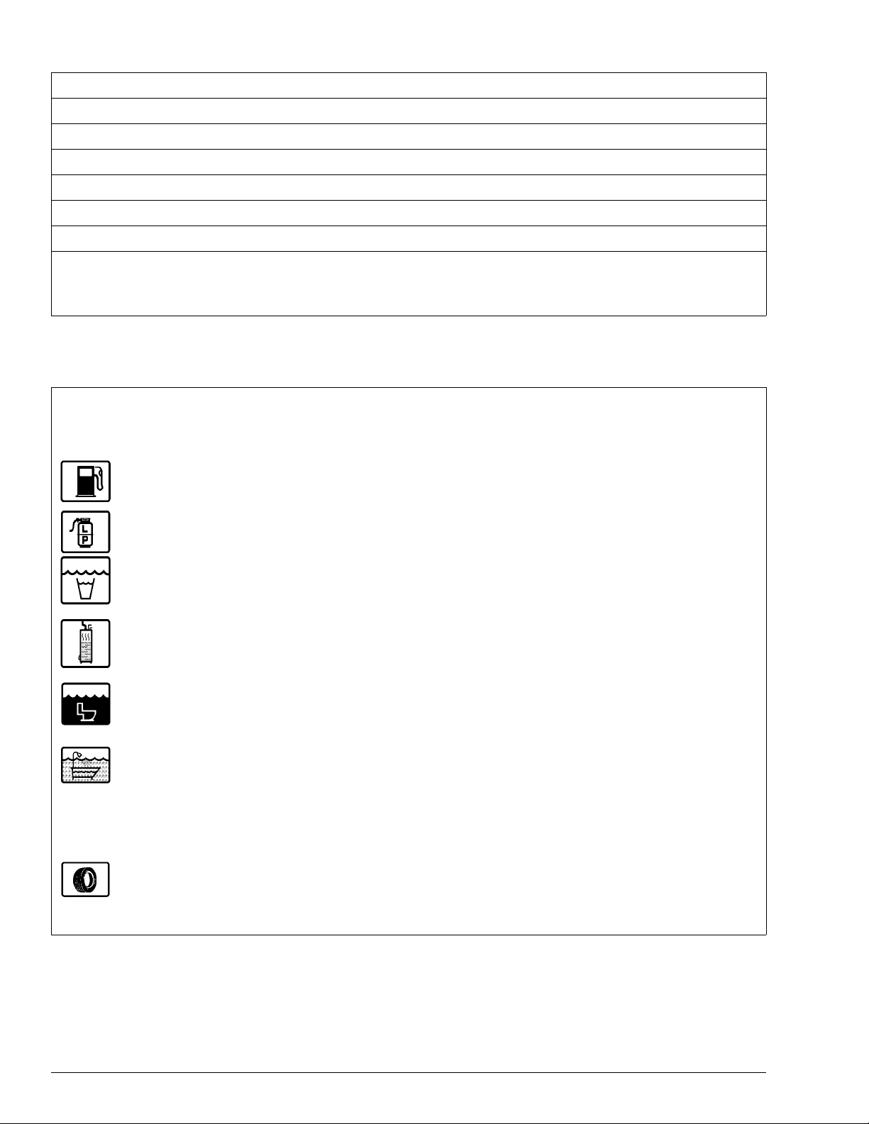
SUBJECT ICONS - To make it easier for you
to find information you’re looking for, we have
placed convenient, pictorial symbols called
“icons” beside many of the subject headings in
this manual. The icons correspond to the subject
matter of the section. These icons were designed
similar to the familiar international symbols
which identify public facilities such as restr ooms
and handicap access. There are several examples
of icons on this page.
PAGE ICONS - The icons at the upper corners of each page correspond to the primary content of each main section of the manual, such as
LP Gas, Electrical, Plumbing, etc. This means
you can flip through the manual either forward or
backward and know exactly which main section
you are looking for just by watching the icons at
the top of the page. This means less paging back
and forth.
We also urge you to read the complete
Chassis Operating Guide provided by the
chassis maker and all other operating information provided by our equipment suppliers
and manufacturers. This is contained in your
Owner INFOCASETM.
This manual should be kept in the vehicle at
all times for personal reference. The operator’s
manual, INFOCASE and chassis operating guide
are to be considered permanent components of
this vehicle. They should remain in the vehicle
when sold to provide the next owner with important safety, operating and maintenance information.
NOTE: The descriptions, illustrations, and spec-
ifications in this manual were correct at
the time of printing. We reserve the right
to change specifications or design without notice, and without incurring obligation to install the same on products
previously manufactured.
CHASSIS OWNER’S
MANUAL
Throughout this manual, frequent reference
is made to the vehicle chassis owner’s manual.
The chassis manual is the operator’s manual provided by Volkswagen, the manufacturer of the
chassis on which this motor home is built. Consult the chassis guide for operating safety and
maintenance instructions pertaining to the Volkswagen chassis section of the motor home.
OWNER’S INFOCASE
Your Owner’s InfoCase contains information
supplied by manufacturers of individual appliances and equipment installed in your motor
home.
Consult this information regarding the operation and care of appliances, accessories and special equipment.
OPTIONS AND EQUIPMENT
Some equipment and accessories described in
this manual may be optional and may not apply to
your coach.
0-1
INTRODUCTION
BEFORE DRIVING
Winnebago or Itasca dealership and they will assist you.
Before sitting in the driver’s seat, always
check around your vehicle to be sure you have
proper clearance for maneuvering. If necessary,
have a passenger help guide you out of a difficult
parking space.
Although your coach features automotive
conveniences like power steering and power
brakes, driving a motor home is different from
driving a car. A motor home is larger and heavier
than an automobile, so it requires more stopping
and passing distance, and more parking and maneuvering space than does a car.
Always be aware of the size of your motor
home. The added height of roof air conditioners,
TV antennas or luggage boxes may cause clearance problems around some tunnels, canopies
and hanging signs. Know the height of your unit
so you can observe posted clearance limits. Also,
remember that some br idges, o ld ones i n particular, may not support the weight of your motor
home. Know the weight of your unit and observe
any posted weight limits.
Remember: Alway use your seat belt and be
sure your passengers do so as well. We also advise making frequent rest stops while traveling to
relieve stress on yourself, your passengers and
your vehicle.
WARRANTY
Your new vehicle is covered by a factory
warranty against defects in material and workmanship. This warranty should be validated immediately and returned to the factory by your
dealer. For additional information, see your
“New Vehicle Limited Warranty” incl uded with
this vehicle.
DRINKING AND DRIVING
Winnebago Industries supports the recommendations of the Presidential Commission on
Drunk Driving.
· Exercise your good judgment and encourage
others to do the same.
· Know the legal limits and do not exceed
them.
· Also know your personal limits, which may
be lower than the legal limits.
· Should you ever exceed your limits, find al-
ternative transportation; call a cab, ask a
friend to drive you home or call a family
member to come and get you.
SERVICE AND
ASSISTANCE
Your Rialta dealer will be glad to provide any
additional information you need, as well as answer any questions you might have about operating the equipment in your motor home. When it
comes to service, remember that your dealer
knows your vehicle best and is interested in your
satisfaction. Your dealer will provide quality
maintenance and any other assistance that you
may require during your ownership of this vehicle.
If you need warranty repairs while traveling,
however you may take your motor home to any
0-2
The presence of alcohol in significant levels
in the blood increases the probability that the
driver will be involved in an accident.
REPORTING SAFETY DEFECTS
If you believe that your vehicle has a defect
which could cause a crash or could cause injury
or death, you should immediately inform the National Highway Traffic Safety Administration
(NHTSA) in addition to notifying Winnebago Industries, Inc.
If NHTSA receives similar complaints, it
may open an investigation, and if it finds that a

safety defect exists in a group of vehicles, it may
order a recall and remedy campaign. However,
NHTSA cannot become involved in individual
problems between you, your dealer, or Winnebago Industries.
To contact NHTSA, you may either call the
Auto Safety Hotline toll-free at 1-800-424-9393
(or 366-0123 in Washington, D.C. area) or write
to: NHTSA, U.S. Department of Transportation,
Washington, D.C. 20590. You can also obtain
other information about motor vehicle safety
from the Hotline.
INTRODUCTION
0-3
INTRODUCTION
VEHICLE CERTIFICATION LABEL
This label contains vehicle identification and other important reference information. The vehicle certification label is located on the sidewall to the left of the steering wheel, or on the driver’s door. Never
remove or destroy this label.
MANUFACTURED BY
3
GAWR:
FRT______ LB______ KG________________ ________________ ______ PSI______ KPA SINGLE
RR. _______ LB______ KG________________ ________________ ______ PSI______ KPA______
THIS VEHICLE CONFORMS TO ALL APPLICABLE FEDERAL MOTOR VEHICLE SAFETY
STANDARDS IN EFFECT ON THE DATE OF MANUFACTURE SHOWN ABOVE.
SERIAL NO. _________________________ VIN______________________________
TYPE ____________________ MODEL ____________________ COLOR__________
5
10
12
SUITABLE TIRE AND RIM CHOICE COLD INFLATION
EXPLANATION OF DATA
1. Chassis manufacturer.
2. Chassis manufacture date.
3. Month and year of manufacture at Win-
nebago Industries.
4. Gross Vehicle Weight Rating: Total permis-
sible weight of the vehicle, including driver,
passengers, total cargo carried (including all
liquids) and equipped with all options.
5. Gross Axle W eight Rating: Total permissible
weight allowed for the front, intermediate*
and rear axles (listed in pounds and kilo-
grams).
6. Suitable Tire Choice: Tires recommended to
meet handling and safety requirements.
INCOMPLETE VEHICLE MANUFACTURED
BY MOTOR CORP.
MONTH AND YEAR OF MANUFACTURE:________
GVWR_______LB _________KG
TIRE RIM PRESSURE
6
1
4
7
11
13
8
14
10. Serial Number: This is the serial number
assigned to the completed vehicle by Winnebago Industries.
11. Vehicle Identification Number (VIN): This
number identifies the chassis on which the
motor home is built.
12. Type: States the NHTSA designated usage
classification for your motor home. MPV
signifies a Multi-purpose Passenger Vehicle.
13. Model: Lists the Winnebago product model
number of your vehicle.
14. Color: Signifies the color code number of the
decor used throughout the vehicle. This
number is necessary for ordering replacement cushions, curtains, carpet, etc.
2
When replacing any of the tires on your
vehicle, always replace with a tire that meets
these specifications.
*Intermediate (INT) data applies only to Class-A
models equipped with tag axle.
7. Suitable Rim Choice: Wheel rims recommended to meet handling and safety requirements. When replacing any of the rims on
your vehicle, always replace with a rim that
meets these specifications.
8. Cold Inflation Pressure: Inflation pressures
recommended (while Cold) fo r the tir es originally equipped on your vehicle. These pressure levels must be maintained to assure
proper handling, safety and fuel economy.
9. Intermediate* and Rear Axle Wheel Configuration: Single or Dual.
9
0-4
INTRODUCTION
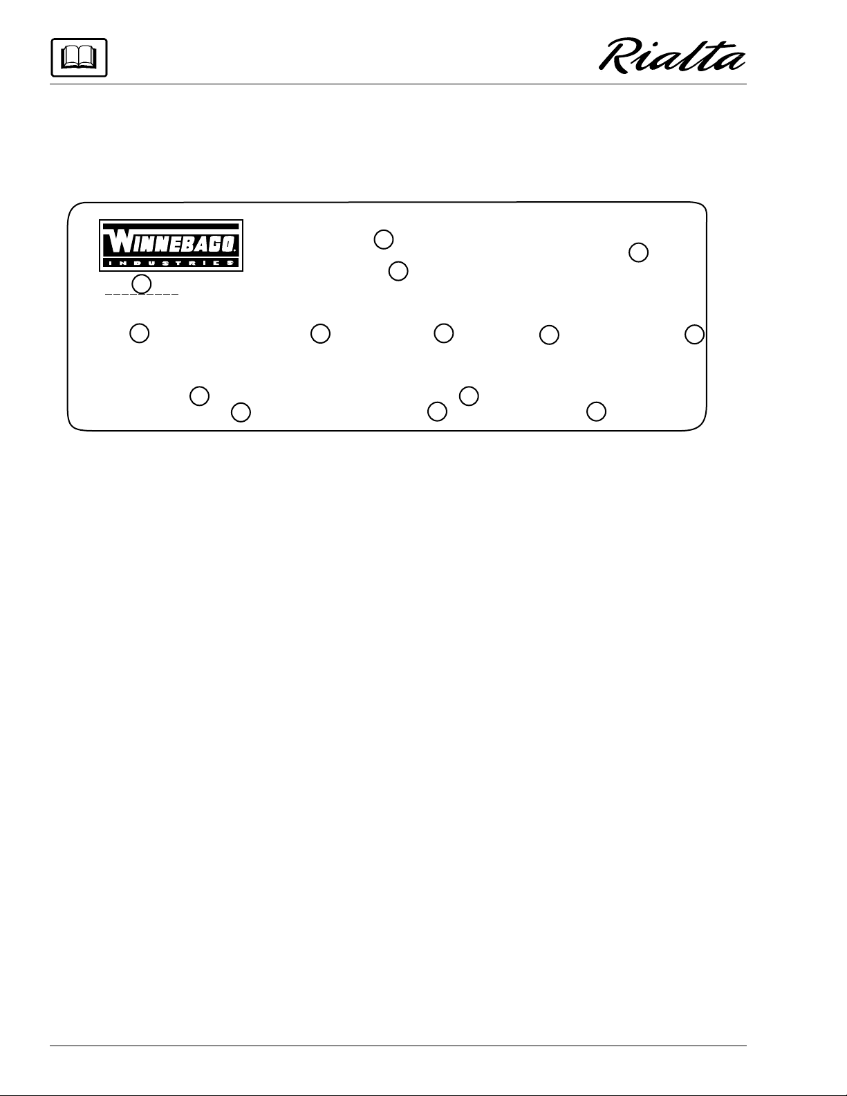
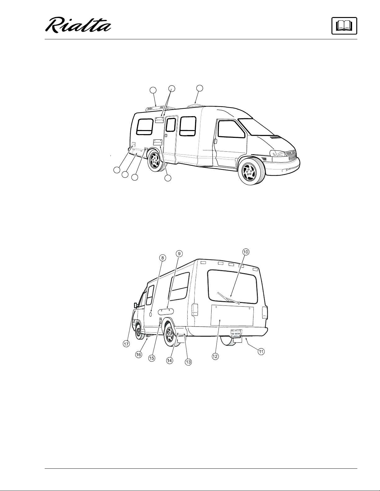
EXTERIOR FEATURE IDENTIFICATION
Model 222QD shown for illustration purposes only.
Actual locations of features depends on your model and option combinations.
1
7
6
5
2
4
1. Roof Air Conditioner Unit
2. Refrigerator Exhaust Vent
3. Roof Vent/Skylight
4. Refrigerator Air Intake/Service Panel
3
5. 110-Volt Outlets
6. LP Gas Tank Compartment
7. Fresh Water Tank Fill
8. City Water Connection
9. Exterior Wash Station/Shower
10. Rear Window Wiper/Washer
11. Spare Tire Storage Carrier
12. Rear Trunk Storage Compartment
13. Sewer Hose Storage
14. Aux. 110-Volt Generator (GenSet)
15. Furnace Intake/Exhaust Ports*
16. Holdi n g Tank Dump Val ves
17. Engine Fuel Fill
*CAUTION: Be careful. These features may become HOT while refrigerator or furnace are in use.
**Also contains shoreline cord storage, generator/shoreline plug in, cable TV connection and
rear window washer reservoir.
0-5

SECTION 1
SAFETY PRECAUTIONS
Read and understand all instructions and precautions in this manual before operating your
new motor home. Throughout this manual, certain items are labeled NOTE, CAUTION and
WARNING. These terms alert you to precautions
that can involve risk to your vehicle or to your
personal safety. Read and follow them carefully.
NOTE: Indicates a special point of information.
CAUTION
Indicates that a failure to observe can
cause damage to vehicle or equipment
WARNING
This symbol is used to alert you to
precautions that involve your personal safety as well as vehicle damage. Read and follow them carefully.
Listed below are some safety precautions that
must be adhered to. These precautions as well as
others that involve damage to equipment are also
listed in the appropriate areas in this manual.
· Never allow passengers to stand or kneel on
seats while the vehicle is moving.
· Sleeping facilities are not to be utilize d while
vehicle is moving.
· Examine the escape window and be familiar
with its operation, but do not use except in an
emergency.
• Inspect the fire extinguisher monthly for
proper charge and operating condition. This
should also be done before beginning a vacation or any extended trip.
DRIVING
· Do not attempt to adjust the driver’s seat
while the vehicle is moving.
· Do not adjust tilt steering in a moving
vehicle.
GENERAL WARNINGS
· Only seats equipped with seat belts are to be
occupied while the vehicle is moving.
· Make sure all passengers have seat belts fastened in a low and snug position so the force
exerted by the belt in a collision will be
spread across the strong hip area. Place the
lap belt across the lap as low on the hips as
possible. Pull the retractor belt so that the belt
is snug and the mechanism takes up the slack.
Pregnant women should wear a lap-shoulder
belt whenever possible, with the lap belt portion worn low and snug throughout the pregnancy.
· Do not operate the cruise control on icy or
extremely wet roads, winding roads, in heavy
traffic, or in any other traffic situation where
a constant speed cannot be maintained.
· Use care when accelerating or decelerating
on a slippery surface. Abrupt speed changes
can cause skidding and loss of control.
· Driving through water deep enough to wet
the brakes may affect stopping distance or
cause the vehicle to pull to one side. Check
brake operation in a safe area to be sure they
have not been affected. Never operate any
vehicle if a difference in braking efficiency is
noticeable.
1-1
SECTION 1
NOT SAFE TO USE COOKING
APPLIANCES FOR COMFORT HEATING
COOKING APPLIANCES NEED FRESH AIR FOR SAFE OPERATION.
BEFORE OPERATION:
1. OPEN OVERHEAD VENT OR TURN ON EXHAUST FAN AND;
2. OPEN WINDOW.
SAFETY PRECAUTIONS
· Adverse weather conditions and extremes in
terrain may affect handling and/or performance of your vehicle. Refer to your chassis
manual for related information.
FUEL & LP GAS
· All pilot lights must be extinguished and appliances turned off while refilling the fuel
tank or LP tank.
· Never smoke while refilling vehicle fuel tank
or LP gas tank.
· Avoid inhaling exhaust gases produced by
burned gasoline, diesel fuel or LP gas in
items such as the range, chassis engine, generator engine, refrigerator, furnace and water
heater. They contain carbon monoxide,
which is an odorless, colorless and poisonous
gas.
closed and door latched securely.
· Never connect natural gas to the LP gas system.
· When lighting range burners do not turn
burner controls to “On” and allow gas to escape before lighting match.
· Portable fuel-burning equipment, including
wood and charcoal grills and stoves, shall not
be used inside the recreational vehicle. The
use of this equipment inside the recreational
vehicle may cause fires or asphyxiation.
· LP gas regulators must always be installed
with the diaphragm vent facing downward.
Regulators that are not in compartments have
been equipped with a protective cover. Make
sure that the regulator vent faces downward
and that the cover is kept in place to minimize
vent blockage which could result in excessive
gas pressure causing fire or explosion.
· The following warning label is located in the
cooking area to remind you to provide an adequate supply of fresh air for combustion.
· Do not bring or store LP gas containers, gasoline or other flammable liquids inside the
vehicle because a fire or explosion may result. LP gas containers are equipped with
safety valves which relieve excessive pressure by discharging gas to the atmosphere.
· Do not alter the LP gas system at any time or
in any way.
· Do not fill LP gas container(s) above 80 percent of capacity. Overfilling the LP gas container can result in uncontrolled gas flow
which can cause fire or explosion. A properly
filled container will contain approximately
80 percent of its volume as liquid LP gas.
· Never use an open flame to test for LP gas
leaks. Replace all protective covers and caps
on LP system after filling. Make sure valve is
1-2
WARNING
IT IS NOT SAFE TO USE COOKING IT IS
COOKING APPLIANCES NEED FRESH AIR FOR SAFE OPERATION.
BEFORE OPERATION:
1. OPEN OVERHEAD VENT OR TURN ON EXHAUST FAN AND;
2. OPEN WINDOW.
APPLIANCES FOR COMFORT HEATING
Unlike large homes, the oxygen supply inside
a recreational vehicle is limited due to its
size. To avoid danger of asphyxiation, provide proper ventilation when using the gas
rangetop or gas oven. It is especially important that the gas oven and range top not be
used for comfort heating. Danger of asphyxiation is greater when these appliances are
used for long periods of time.
SECTION 1
SAFETY PRECAUTIONS
LP GAS LEAKS
The following label is located in the vehicle
near the range area. If you smell gas within the
vehicle, quickly and carefully perform the procedures listed.
IF YOU SMELL GAS
1. Extinguish any open flames, pilot
lights and all smoking materials.
2. Do not touch electrical switches.
3. Shut off the gas supply at the tank
valve(s) or gas supply connection.
4. Open doors and other ventilating
openings.
5. Leave the area until odor clears.
6. Have the gas system checked and
leakage source corrected before
using again.
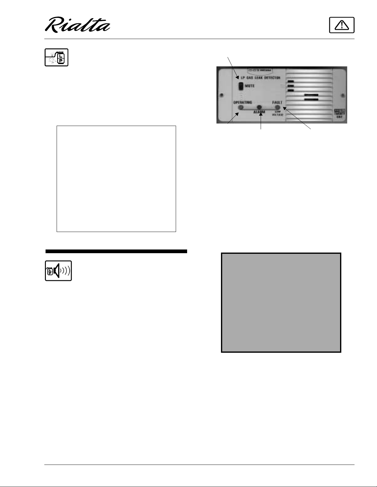
Press to Stop Alarm
Green
(Active)
Red
(Alarm)
Amber
(Low Batt.)
If the Alarm Sounds
If the alarm sounds, do not touch any electrical switches. Immediately turn off the main LP
tank valve and all LP appliances, open all windows and roof vents, and leave the coach until
the alarm stops sounding.
If the alarm keeps sounding at regular intervals, a leak may be present. Contact your dealer
or an LP gas service center to have the problem
corrected before using the LP system again.
LP GAS ALARM
Your coach is equipped with an LP gas detector which sounds an alarm if an unsafe amount of
LP gas is present inside the coach. Because LP
gas is heavier than air, the detector is located on
the rear galley cabinet face near the floor of the
coach.
A green light on the face of the alarm shows
when the unit is active. If the detector senses LP
gas, the alarm will make a loud, pulsating sound
and the red light will come on. Pressing the
“MUTE” button will stop the alarm for 60
seconds. If there is no more detectable LP gas,
the alarm will stay off. I f the dete ctor still se nses
LP gas by the end of the 60 second mute mode,
the alarm will sound again.
WARNING
Never use an open flame to test for
gas leaks.
When testing for gas line leaks with a
soapy water solution, DO NOT use a
detergent containing ammonia or
chlorine. These substances may generate a chemical reaction causing corrosion to gas lines, resulting in
dangerous leak conditions.
Power Connection
The gas alarm is powered by the coach batteries. If the battery cable is disconnected from the
batteries or the fuse is blown, the alarm will not
work. The LP gas alarm fuse is located on the
power converter fuse panel shown on page 6-6.
If the coach batteries become extremely
drained (8.5 volts or less), the amber Low
Voltage/FAULT light on the face of the alarm
will come on, and in some rare cases the LP alarm
may begin to sound on its own. This condition i s
1-3
SECTION 1
SAFETY PRECAUTIONS
not likely to occur except during storage
situations when coach battery charge is not being
restored by the converter charger.
Because the LP gas alarm is connected directly to the auxiliary battery, it is always drawing a
small amount of current. Even though this current
draw is slight, it could drain the coach battery
during storage periods of 30 days or longer. We
recommend disconnecting the battery cables
from the auxiliary battery during extended storage periods to avoid discharge.
Other Combustible Fumes or Vapors
This alarm is designed to detect the presence
of LP gas, however there are other combustible
fumes or vapors which may be detected by the
sensor. These include: alcohol, liquor, deodorants, colognes, perfumes, wine, adhesives, lacquer, kerosene, gasoline, glues, most all cleaning
agents and the propellants of aerosol cans. Most
are lighter than air in their vapor state and will
only be detected when the area is closed up.
Glues and adhesives may exhaust hydrocarbon
vapors for months after they are applied. They
are easily activated by high temperatures. If you
close up an RV coach on a hot day, the chemicals
used in its construction may be detected for
months after the coach was manufactured.
Further Information
See the manufacturer’s information entitled
“Your LP Gas Detector” in your Owner/InfoCase
for further instructions on nuisance alarms and
care and testing of the LP gas detector.
cord into an outlet which is not grounded and
do not adapt the plug to connect to a receptacle for which it is not designed.
· Do not attach an extension cord to the utility
power cord.
· Be sure that all electrical appliances to be
used contain 3-prong plugs for proper
grounding.
· Avoid overloading electrical circuits. Replace fuses or circuit breakers with those of
the same size and amperage rating only. Never use a higher rated fuse or breaker.
· Use caution when handling or working near
electrical storage batteries. Always remove
jewelry and wear protective clothing and eye
covering. Avoid creating sparks.
LOADING
· Store or secure all loose items inside the motor home before traveling. Possible overlooked items such as canned goods or small
appliances on the countertop, cooking pans
on the range, or free-standing furniture items
can become dangerous projectiles during a
sudden stop.
· Be aware of GVWR, GAWR and individual
load limit on each tire. (See “Loading the
Motor Home” in Section 4.)
ELECTRICAL
· Careless handling of electrical components
can be fatal. Never touch or use electrical
components or appliances while feet are bare,
while hands are wet, or while standing in water or on wet ground.
· Improper grounding of the vehicle can cause
personal injury. Do not plug the utility power
1-4
· Never load the motor home in excess of the
gross vehicle weight rating or the gross axle
weight rating for either axle.
MAINTENANCE
· Do not remove the radiator cap while engine
and radiator are still hot. Always check cool-
ant level visually at the see-through coolant
reservoir.
· Never get beneath a vehicle that is held up by
a jack.
· Do not mix different construction types of
tires on the vehicle such as radial, bias or belted tires, as vehicle handling may be affected.
Replace tires with exact size, type and load
range See page 0-3 for tire specifications.
· Do not attempt to start the vehicle by hot wiring.
FORMALDEHYDE INFORMATION
WARNING
Although Winnebago did not use
formaldehyde based adhesives to
manufacture this vehicle, some raw
materials used, such as plywood, carpet and fabrics may contain formaldehyde based adhesives which may
release formaldehyde fumes into the
air for an unknown period of time
until total dissipation occurs. Individuals who are allergic to formaldehyde
gas fumes may experience irritation
to eyes, ears, nose and throat.
Although long range effects are not
well understood, testing to date has
not revealed any serious health
effects in humans at the leve l of emission from these products.
NOTE: To aid in dissipation, ventilate the
vehicle by opening all windows and circulating the air with a fan.
SECTION 1
SAFETY PRECAUTIONS
CARBON MONOXIDE
WARNING
WARNING
A voi d inhaling exhaust gases, as they
contain carbon monoxide, which is a
colorless, odorless and poisonous gas.
If you suspect that exhaust fumes are entering
the passenger compartment, have the cause determined and corrected as soon as possible. If you
must drive under these conditions, drive only
with ALL WINDOWS FULLY OPENED.
The best protection against carbon monoxide
entry into the vehicle body is a properly maintained engine exhaust and ventilation system. It is
recommended that the exhaust system and body
be inspected by a qualified motor home service
center.
· Each time the vehicle is raised for an oil
change.
· Whenever a change in the sound of the ex-
haust system is noticed.
· Whenever the exhaust system, underbody or
rear of the vehicle is damaged.
To allow proper operation of the vehicle’s
ventilation system, keep front ventilation inlet
grill clear of snow, leaves or other obstructions at
all times. DO NOT OCCUPY A PARKED VEHICLE WITH ENGINE RUNNING FOR AN
EXTENDED PERIOD.
Do not run engine in confined areas, such as a
garage, except to move vehicle in or out of area.
When vehicle is stopped in an UNCONFINED
area with the engine running for any more than a
short period, adjust heating or cooling system to
force outside air into the vehicle as follows:
1. Set fan to medium or high speed and vent
control to air.
2. On vehicles equipped with air conditioning,
set fan to medium or high speed and set control to obtain maximum vent air.
1-5
SECTION 1
RED LOOP
SAFETY PRECAUTIONS
Rear windows should be closed while driving
to avoid drawing dangerous exhaust gases into
the vehicle.
CARBON MONOXIDE
ALARM
Your coach is equipped with a carbon monoxide (CO) alarm, located on the underside of the
overhead cabinet above the left rear dinette seat.
InfoCase. It includes information on precautions,
operational testing, and battery/sensor replacement.
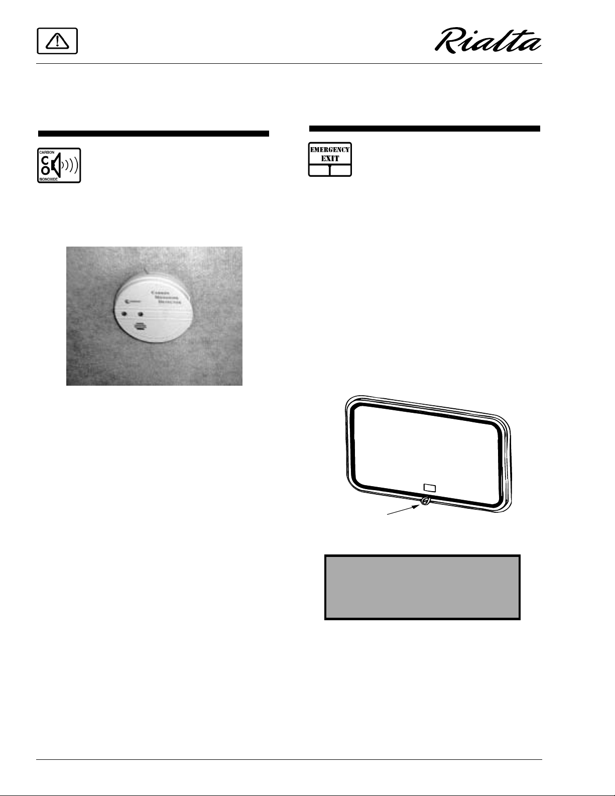
EMERGENCY EXITS
Emergency Exit Windows
Your motor home is equipped with an
emergency exit window in the rear of the vehicle
which functions as an escape exit in an emergency situation.
The glass is installed with a rubber extrusion.
It is opened by pulling on the red plastic loop,
located at the bottom of the window, until the
rubber cord is completely removed. This allows
the window to be pushed out. Instructions for
removal are also located on a label on the glass
for quick reference and for passengers who may
not be familiar with the exit. Be sure this label is
never removed or destroyed.
The CO alarm is powered by a 9-volt battery
and contains a sensor that is designed to detect
toxic carbon monoxide gas fumes resulting from
incomplete combustion of fuel. It will detect CO
gas from any combustion source such as the
furnace, gas range/oven, water heater, refrigerator, chassis engine, and electric generator engine.
Monthly Testing
Press the TEST button on the face of the alarm
periodically (at least monthly) to check the function of the alarm and condition of the battery. If
the alarm begins to beep every few seconds, the
battery may be weak and need replacement.
(Press the TEST button to be sure before replacing the battery. If the alarm sounds, the battery
may still be okay. If the alarm still beeps every
few seconds, check the smoke detector also. The
“low battery” warning beep is similar on many
alarm devices, so the origin of this electronic
sound can be deceiving.)
Further Information
Please read the information provided by the
manufacturer, which is included in your Owner
WARNING
Use emergency window for emergency exit only . Do not test for proper
operation.
If the cord is released by accident, but the
glass remains in place, the cord can be replaced
using a blunt instrument, preferably one made of
plastic. We suggest you contact your dealer for
assistance.
1-6
SECTION 1
SAFETY PRECAUTIONS
WARNING
Use care when exiting emergency
window, as broken glass may be
present in the exit area.
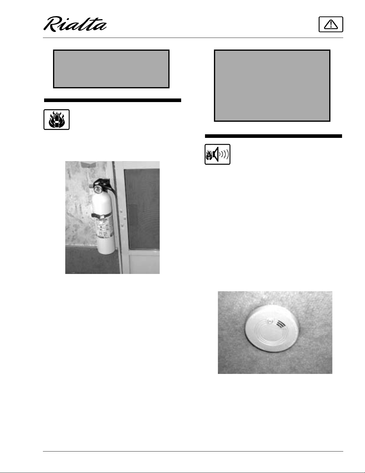
FIRE EXTINGUISHER
A dry chemical fire extinguisher is located
near the floor by the side entrance door.
We recommend that you become thoroughly
familiar with the operating instructions displayed on the side of the fire extinguisher or in
the information supplied in your Owner InfoCase.
We also recommend that you inspect the fire
extinguisher for proper charge at least once a
month in accordance with National Fire Protection Association (NFPA) recommendations as
stated on the label. If the charge is insufficient,
the fire extinguisher must be replaced.
WARNING
Do not test the fire extinguisher by
discharging it. Partial discharge can
cause leakage of pressure or contents
which would render the unit inoperative when needed. When using the
fire extinguisher, aim the spray at the
base of the fire.
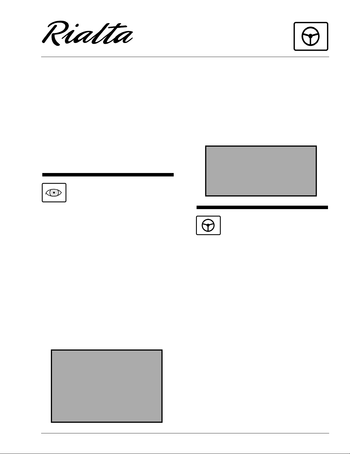
SMOKE ALARM
Your motor home is equipped with a smoke
alarm located on the underside of the overhead
cabinet above the right rear dinette seat. This
alarm meets U.L. Standard 217 and NFPA Standard 74 for operation of smoke detection devices.
1. The smoke alarm should be tested for correct
operation each time the vehicle is brought
out of storage, before each trip, and at least
once a week during motor home use. To test
the electronics, firmly depress the button. To
test that smoke reaches the sensor, blow
smoke in a careful, fire-safe manner into
your smoke alarm.
2. Your smoke alarm will not work without
power. Never remove the battery to quiet the
alarm. When your smoke alarm “beeps”
about once a minute the battery is weak.
Install a new battery immediate ly. Be sure to
use only batteries specified in manual or on
unit. Test unit after installing a new battery.
1-7

SECTION 1
SAFETY PRECAUTIONS
3. Clean and vacuum the openings on your
smoke alarm once a month.
4. Do not open the smoke alarm or try to repair
it. For repl acem ent inform ati on se e wa rra nty
in Owner’s Manual.
5. Smoke alarms have technical limitations and
may not respond in all situations. FIRE PREVENTION is your best safeguard.
See your Owner InfoCase for further informa-
tion.
1-8
SECTION 2
DRIVING YOUR MOTORHOME
(See also Safety Precautions, Section 1 of this
manual.)
NOTE: This section describes only those instru-
ments and controls which are unique to
this motor home. For complete information regarding all other equipment, controls and instructions, consult the
Volkswagen chassis owner’s manual or
the individual equipment manufacturer’s
information provided in your Owner
InfoCase. Some items described may be
optional or unavailable on your vehicle.
BEFORE ENTERING YOUR
VEHICLE
Before entering your vehicle, there are a few
recommended procedures that will aid in your
driving safety and equipment.
1. Be sure that the windows, mirrors and light
lenses are clean and unobstructed.
2. Make sure all exterior lights operate prop-
erly.
3. Check tires for proper cold inflation pres-
sures and inspect for any unusual wear.
4. Check wheel lug nuts for tightness.
5. Look beneath the vehicle for noticeable fluid
leakage.
6. Check fluid levels and fill if necessary. This
includes engine oil, transmission fluid, coolant, brake fluid, power steering fluid and
windshield washer solvent.
WARNING
The transmission must be in P (Park)
or N (Neutral) and park brake engaged
while performing any checks or adjustments.
The engine should be shut off unless
specifically required for a certain procedure.
7. Unhook and store sewer and water supply
hoses.
8. Retract step.
9. Be sure that all of your cargo is secured in
event of a sudden stop or an accident.
10. Check around your vehicle in all directions
to assure that you have proper clearance.
11. Lower TV antenna.
12. Disconnect and store shoreline.
WARNING
Before driving your vehicle, be sure
you have read the entire operator’s
manual and that you understand your
vehicle’s equipment completely and
how to use the equipment safely.
BEFORE DRIVING YOUR
VEHICLE
Before preparing to drive your vehicle, here
are a few recommended procedures that will add
to your driving safety and enjoyment.
1. Be sure that you adjust the interior and exte-
rior rear view mirrors to your driving preference.
2. Adjust the driver's seat for proper distance
from foot pedals and steering wheel to allow
for safety and ease in controlling your vehicle.
3. Place front seats in the forward facing posi-
tion.
4. Be sure to fasten all safety belts to fit you
comfortably, but tight enough to obtain the
full safety of the belts.
5. Make sure all doors are completely shut and
locked. When the doors are shut and locked,
there is less change of the doors flying open
in event of an accident. It also prevents unintentional opening of doors and keeps intruders out of your vehicle.
2-1
SECTION 2
DRIVING YOUR MOTOR HOME
6. Check to see that all gauges are operating
properly.
7. Check the fuel level in the vehicle.
8. Be certain that the fire extinguisher is fully
charged and secure in its mounting bracket.
CAUTION
Be sure hood and all compartment
doors are latched securely before
driving vehicle
KEYS
Your motor home is supplied with
several sets of keys. In addition to the
chassis manufacturer's ignition key, you receive
keys for front doors, entrance door, and exterior
compartment doors.
Each set of keys has an identification number,
either a small metal tag or stamped into the key
head. Record these numbers and keep them in a
safe place. In case keys are lost or stolen, your
dealer or a locksmith can provide you with duplicate keys or modify the locks.
FUEL INFORMATION
GASOLINE FUEL FILL
REMOVING THE FUEL CAP
When removing the gasoline cap, slowly ro-
tate it only far enough to allow pressure to re-
lease. After any "hissing" sounds stop, continue
removing the cap.
FILLING THE TANK
Do not overfill the fuel tank. Allow gasoline
to pump into the tank until the auto-shutoff valve
in the fuel pump nozzle stops the flow of fuel, indicating a full tank. This provides a pre-determined vapor space at the top of the tank to allow
for expansion of the gasoline.
CAUTION
Continuing to fill above this level
may cause damage to the fuel/evaporative emission system.
Fuel Tank Capacity: 21.1 gals.
REPLACEMENT FUEL CAPS
To protect gasoline system from excessive
pressure or vacuum, or from sudden pressure, replace lost caps with caps of the same design
available from your dealer.
FUEL SELECTION
Refer to your Volkswagen chassis owner’s
manual for the manufacturer's recomm endations
on proper fuel selection.
WARNING
Modern fuel systems may build up
pressure within the tank as the gasoline warms during use or in hot weather.
Under certain conditions, sudden
release of this pressure when removing the gasoline cap can spray gasoline from the fuel fill opening,
causing a possible hazard.
2-2
STARTING AND
STOPPING ENGINE
Refer to your Volkswagen chassis owner’s
manual for the manufacturer's recomm endations
on starting and stopping the engine.
ENTRANCE DOOR LOCK
AND HANDLE
NOTE: Keys should always be removed when
leaving the vehicle. Since doors can be
locked without keys, make sure they have
been removed from the ignition before
locking the driver’s compartment.
The entrance door may be opened from out-
Entrance Door Handle - Outside
Entrance Door Handle - Inside
side the vehicle by pulling the door handle outward. To open the door from inside, pull upward
on the door handle. When the door is locked, neither the inside nor the outside door handle can be
operated. It can be locked and unlocked from the
outside of the vehicle by inserting the key into the
lock and turning.
Pull
SECTION 2
DRIVING YOUR MOTOR HOME
CAUTION
When releasing security night lock,
be sure to retract bolt before opening
door latch to prevent drag on bolt pin.
Instruct all passengers in operation of
this door catch system as well as
emergency exit window.
Never force the inside door handle
downward, as damage could occur.
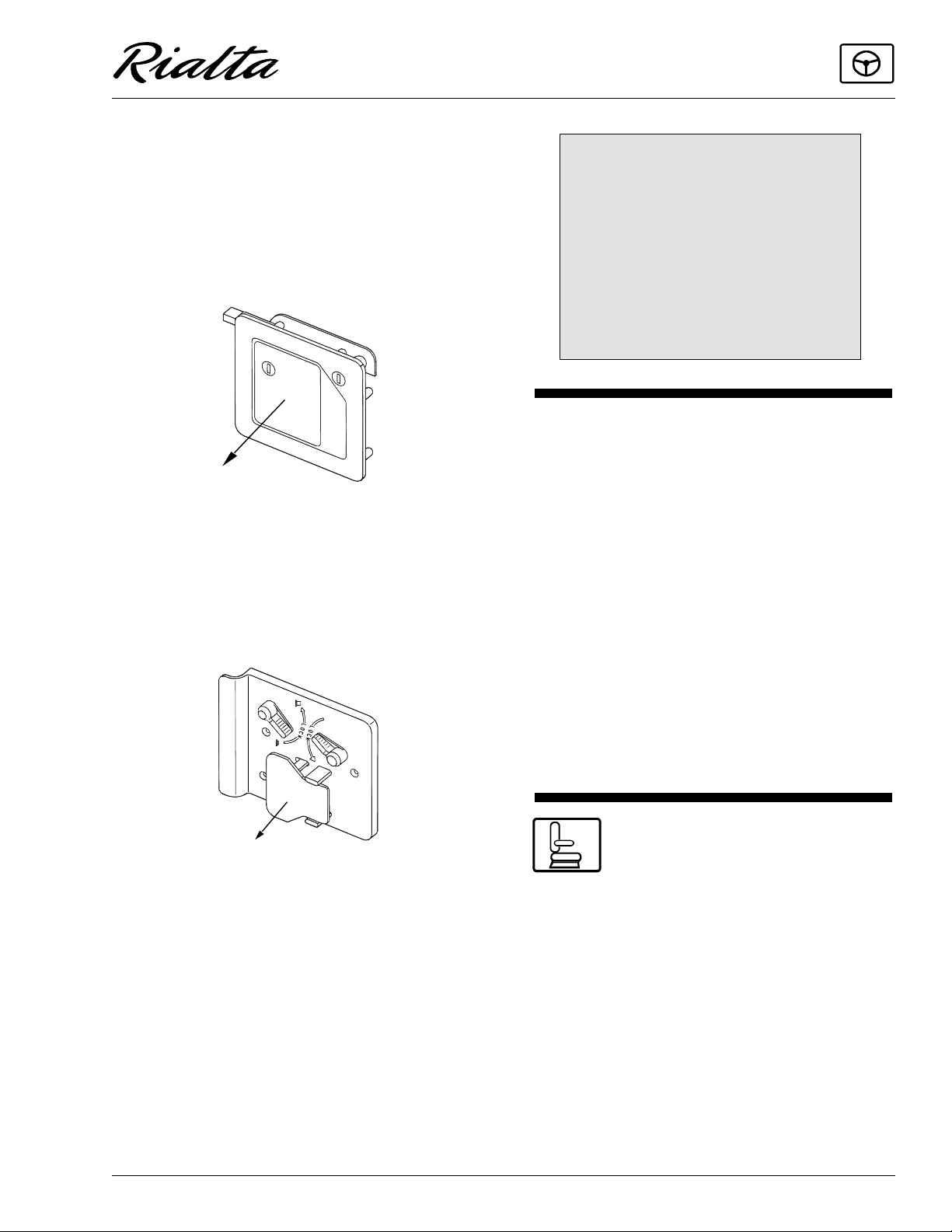
DRIVER COMPARTMENT DOOR
LOCKS
Consult your Volkswagen chassis owner’s
manual.
To lock the door from inside, rotate the lock
levers as indicated. The deadbolt lock is for added security and should be used as a security night
lock.
Pull
Lubricate t he lock s peri odically with gra phite
to maintain good working condition.
Power Locks
The power locks on the front driver and
passenger doors will lock and unlock both front
doors and the side entrance door. As is typical for
most multi-purpose vehicles, the side entrance
door lock can be controlled by the front door
power locks, but not vice versa. The side door
cannot lock any other door except itself. Before
leaving the vehicle by way of the side entrance
door, be sure the front doors are locked by pressing one of the front door lock knobs or turning
one of the front door key locks.
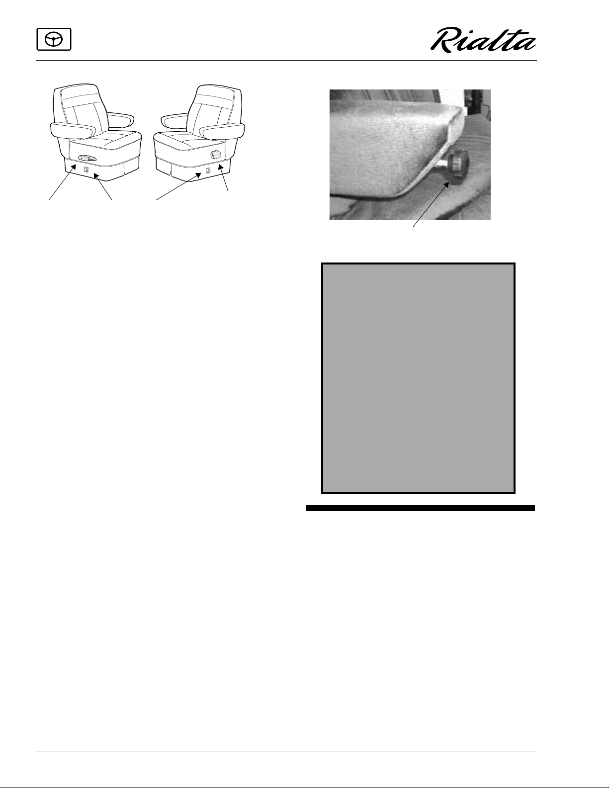
DRIVER AND CO-PILOT
SEATS
The front seats have slide, recline and swivel
features. The seat adjustment controls are located
on the lower left side of the seat base.
2-3
SECTION 2
DRIVING YOUR MOTOR HOME
Lift to
Recline
Lift to
Swivel
Lift to
Slide
Driver Seat
Rotate forward to
increase l um bar
support
To Swivel Seats: Lift the release lever, locat-
ed on the side of the seat, and rotate seat. The
seats are designed to lock only when returned to
the forward facing position.
NOTE: A warning chime will sound when the ig-
nition key is turned on if the passenger
seat swivel mechanism is not locked in
the forward facing position.
To Recline Seats: Lift the reclining lever,
lean back to desired incline and release the lever.
To return to the upright position, lift the lever and
lean body forward. Allow the seat to return to the
desired position and release the lever.
To Adjust Lumbar Support (driver seat
only): Turn the knob on the left side of the seat
forward to increase support and rearward to decrease support.
To Adjust Armrest Position (driver seat
only): Turn the knob at the front end of the arm-
rest clockwise (tighten) to raise armrest position
and counterclockwise (loosen) to lower arm position.
Adjustment Knob
WARNING
Do not adjust driver’s seat while
vehicle is in motion.
After adjusting seat, always use body
pressure to make sure slide and
swivel locking mechanism have
engaged.
Be sure all swivel seats are locked in
the forward facing position while the
vehicle is in motion.
Only seats equipped with seat belts
are to be occupied while the vehicle is
in motion.
COMPANION SEATS - Model 222QD
The companion seats not only provide additional passenger seating, but can be converted to
sleeping facilities as well. See Companion Seat/
Bed Conversion on page 8-11 for complete instructions.
Storage com partments are loc ated beneath t he
companion seats. The passenger side seat has a
door on the rear. The driver side seat has a door
on the aisle side.
2-4
Seat Back Adjustment (Recline)
The angle of the companion seat back can be
adjusted to three positions:
· Lift front of seat cushion up and pull forward.
SECTION 2
Swivel
RELEASE
DRIVING YOUR MOTOR HOME
· Lower seat cushion while positioning the side
pegs into the angled notches on the seat rails.
NOTE: Notches to be used depends on angle
of recline desired. The farther forward, the
greater the angle of recline.
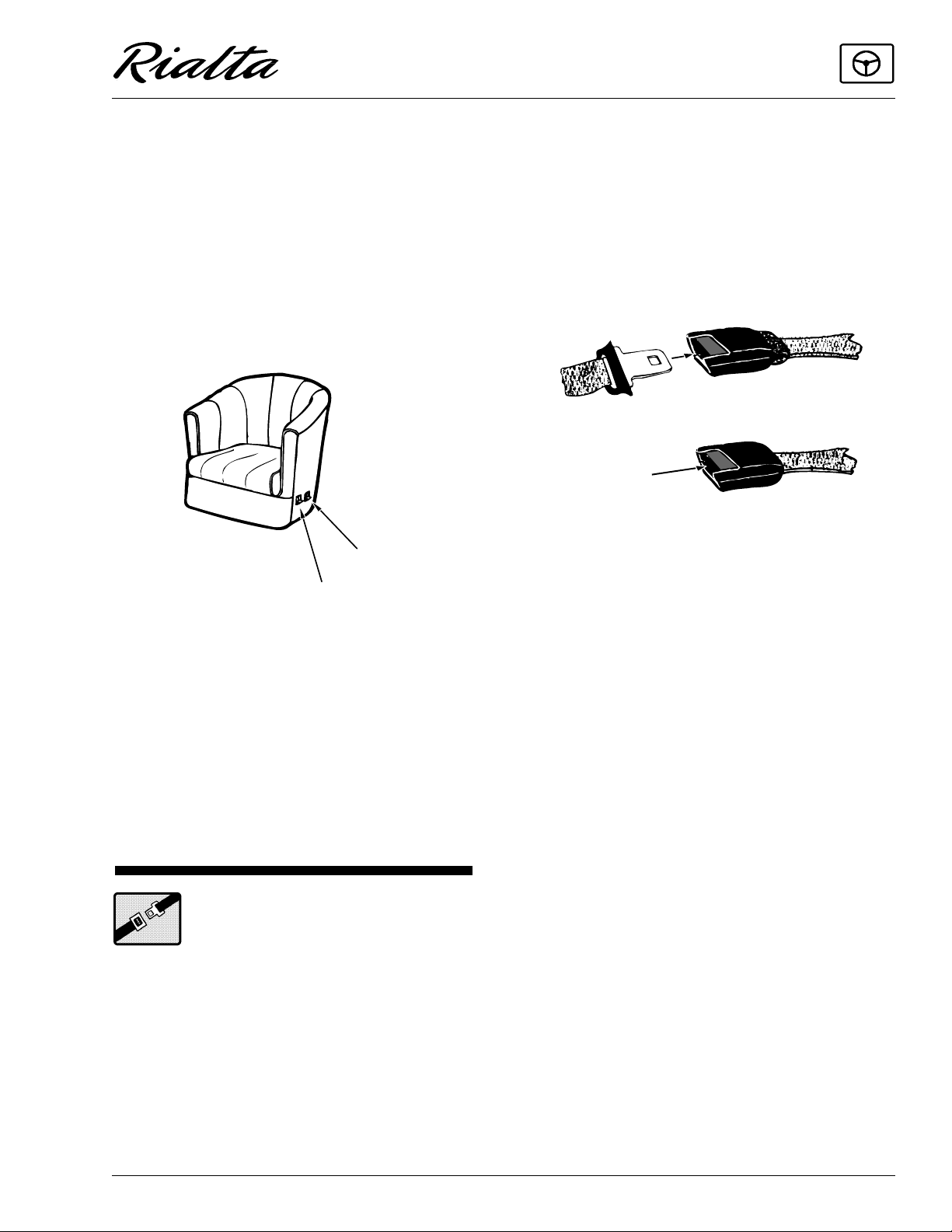
LOUNGE SEAT - Models 222FD & 222HD
The swivel/slider lounge seat provides addi-
tional passenger seating.
The swivel will lock in the center facing posi-
tion for your safety while the vehicle is moving.
Lift to
Slide
Lift to
Swivel: Pull up on the swivel lever located on the
lower left hand side of the seat. The seat will lock
into place whenever it reaches the center aisle
facing position.
Always return the seat to t he aisle facing posi tion
for proper use of seat belts while traveling.
Slide: Pull up on the slide lever located on the
lower left hand side of the seat. Slide to the desired position and release the lever.
them in the doors or in the seat mechanism. After
any serious accident, any safety belts which were
in use at the time should be replaced.
To Fasten and Adjust
The 3-point seat belts in your coach are
equipped with automatic locking retractors that
let you easily adjust your seat belt to the proper
length for passenger safety.
PRESS
TO
· Grasp the end of the belt and pull smoothly
outward from the seat to the required length,
then insert into buckle. Be sure belt is not
twisted before fastening.
· Feed any excess belt length back toward the
seat so the belt retractor will lock the belt at
the proper length for your body when released.
· Do not jerk the belt or pull out too quickly be-
cause it will lock prematurely and require you
to reset the belt retractor.
· Reset the belt retractor by letting the belt go
all the way back to the starting point, then
pull slowly and smoothly outward.
SEAT BELTS
Seats intended for occupancy while the vehicle is in motion are equipped with seat belts for
the protection of the driver and passengers. The
lap belts must be worn as low as possible and fit
snugly across the hip area. Always sit erect and
well back into the seat. To gain full protection of
the safety belt, never let more than one person use
the same safety belt at any one time, and do not
let the safety belts become damaged by pinching
To Release:
Depress button on end of buckle and pull belt
out of buckle.
Hold onto the tongue when you release it
from the buckle to keep it from retracting too rapidly.
2-5
SECTION 2
DRIVING YOUR MOTOR HOME
WARNING
Snug and low belt positions are
essential. This will ensure that the
force exerted by the lap belt in a collision is spread over the strong hip area
and not across the abdomen, which
could result in serious injury.
Only seats equipped with seat belts
are to be occupied while vehicle is in
motion.
When the lap-shoulder belt is in use, the lap
portion must ride across the strong hip area and
the shoulder portion must ride diagonally over
the shoulder blade toward the buckle.
The shoulder belt is designed to lock only
during a sudden stop, sudden body movement or
a collision. At all other times it will move freely
with the occupant.
WARNING
Never wear the shoulder belt in any
position other than as stated above.
Failure to do so could increase the
chance or extent of injury in a collision.
CARE AND CLEANING
· Be careful not to damage the belt webbing
and hardware. Take care not to pinch them in
the seat or doors.
· Inspect the belts and hardware periodically.
Check for cuts, frays, and loose parts. Dam-
aged parts should be replaced. Do not remove
or modify the belt system.
· Keep belts clean and dry. If the belts need
cleaning, use only a mild soap and water
solution. Do not use hot water. Do not use
abrasive cleaners or bleach. These products
may weaken or damage the belts.
· Replace any belt assembly that was used dur-
ing a severe impact. Replace the complete
assembly even if damage is not apparent.
CHILD RESTRAINTS
All 50 of the United States and the District of
Columbia now require the use of the child/infant
restraint systems for children in vehicles.
A properly installed and secured child
restraint system can help reduce the chance or
severity of personal injury to a child in an accident or during a sudden maneuver. Children may
be injured in an accident if they are not seated in
a child restraint which is not properly secured.
A child restraint system is designed to be secured in a vehicle seat by a lap belt or the lap belt
portion of a lap-shoulder belt. According to accident statistics, children are also safer when properly restrained in rear seating positions than in
front seating positions.
When purchasing a child restraint system:
1. Look for the label certifying that it meets all
applicable U.S. Federal Motor Vehicle
Safety Standards (FMVSS) or, in Canada,
requirements of the Children's Car Seats and
Harnesses Regulations (CCSHR).
2. Make sure that it will attach to your vehicle
and restrain your child securely and conveniently so that you are able to install it correctly each time it is used.
3. Be certain that it is appropriate for the child's
height, weight and development. The
instructions and/or the regulation label
attached to the restraint typically provides
this information.
4. Review the instructions for installation and
use of the restraint. Be sure that you understand them fully and can install the restraint
properly and safely in your vehicle.
MIRRORS
Always adjust mirrors for maximum rear visibility before driving off. Make sure the seat is
adjusted for proper vehicle control and that you
are sitting back squarely into the seat.
See your Volkswagen owner’s manual for
instructions on adjusting power mirrors.
2-6
INSTRUMENT PANEL
GAUGES AND CONTROLS
See your Volkswagen owner’s manual for
detailed information on Volkswagen instrument
gauges, vehicle controls and other Volkswagen
original equipment.
STEERING COLUMN CONTROLS
See your Volkswagen owner’s manual for all
controls located on the steering column or steering wheel.
WARNING
Do not operate the cruise control on
icy or extremely wet roads, winding
roads, in heavy traffic, or in any other
traffic situation where a constant
speed cannot be maintained.
SECTION 2
DRIVING YOUR MOTOR HOME
Aux. Start Switch
Press and hold the switch while turning the
ignition key to the start position to temporarily
route power from the coach battery to the engine
starter. When you release the switch, the coach
battery is no longer connected to the starter.
AUTO AIR CONDITIONER/
HEATER
RADIO/CASSETTE PLAYER
Most models are available with a standard
AM/FM radio/cassette player or optional AM/
FM/CD player to provide high quality stereo
sound for your traveling and living enjoyment.
Refer to your Owner InfoCase for operating and
care instructions.
AUXILIARY START SWITCH
The auxiliary start switch can be used to provide emergency starting power to engine starter
from the coach battery if the automotive battery
is dead or too weak to start the engine. The auxiliary start switch is located on t he overhea d console in the headliner above the rearview mirror.
See your Volkswagen Owner’s Manual for
operating instructions for dash mounted automotive heater-air conditioner controls.
NOTE: The automotive air conditioner is not de-
signed to cool the entire interior of the
motor home, but is intended to cool the
driver’s compartment only.
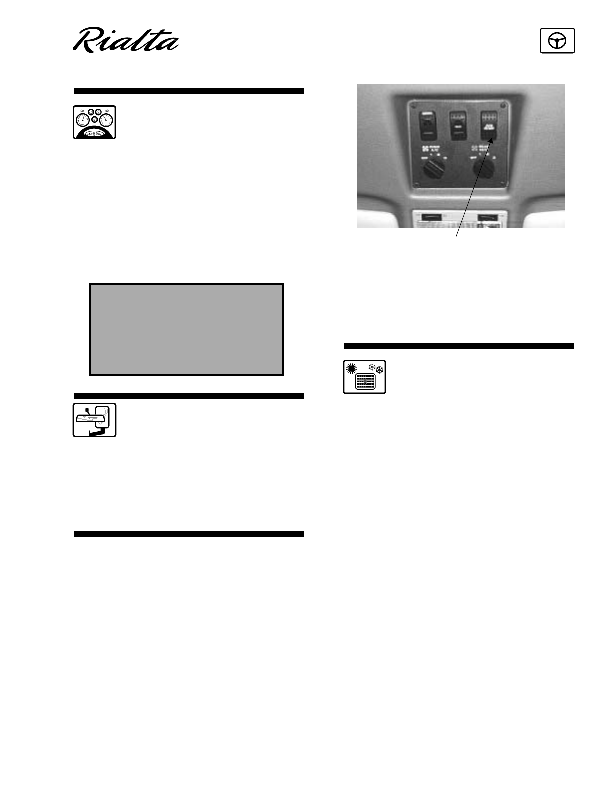
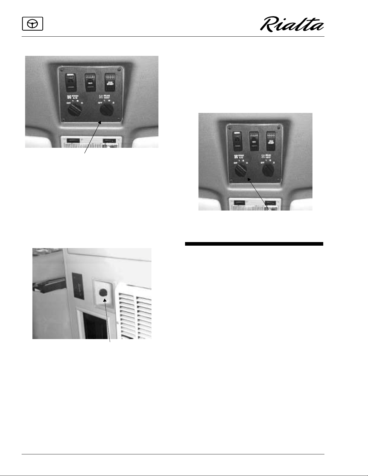
REAR AUTOMOTIVE HEATER
The rear automotive heater supplies heat to
the rear portion of the coach while driving. The
fan is controlled by a 3-speed rotary switch. The
rear heater fan speed control is located on the
overhead console in the headliner above the review mirror.
2-7
SECTION 2
DRIVING YOUR MOTOR HOME
Rear Heater Fan Control
Temperature Control (Model 22QD & 22HD)
The temperature control is located on the face
of the wardrobe cabinet. Turn the knob counter
clockwise (to the left) to increase temperature
and clockwise (to the right) to lower the temperature.
To shut heat off, turn the knob completely to
the cold side and turn the dash switch to OFF.
automotive A/C must be on for the overhead A/C
to operate. The A/C fan speed control is located
on the overhead console in the headliner above
the rearview mirror.
Temperature is controlled by the automotive
air conditioner lever on the dash. See your Volkswagen owners manual for instructions on auto
air conditioner operation.
Overhead A/C Fan Control
Rear Heater Temperature Control
(Model 22QD & 22HD)
NOTE: Model 22FD has a ducted rear heater
system that does not require a separate
rear temperature control.
AUXILIARY AUTOMOTIVE AIR
CONDITIONER (Op tio na l)
The auxiliary air conditioner is mounted in
the cab headliner, with four vents aiming toward
the rear area of the coach. The dash-mounted
REAR WINDOW DEFOGGER
(Optional)
The rear window defogger works only when
the ignition switch is on. The rear defogger
switch is located on the overhead console in the
headliner above the rearview mirror.
To use the rear window defogger, press the
switch and release. A small light in the switch
will light up to alert you when the defogger is on.
The defogger has an electronic timer that will
turn the defogger grid off automatically after 10
minutes of operation. You may also turn the defogger off when the window is clear by pressing
the switch to the off position.
2-8
Rear Defogger Switch
SECTION 2
DRIVING YOUR MOTOR HOME
NOTE: The rear window defogger is not de-
signed to melt heavy snow or ice. Always
remove snow and ice before driving off.
Energy Tip
Turn off any electrical items or accessories
(lights, fans, defoggers, etc.) when not being
used. This reduces fuel consumption by cutting
down electrical load on the automotive alternator. When the load inc reases, the electric al “pull”
on the alternator causes the engine to work harder
also, increasing fuel consumption.
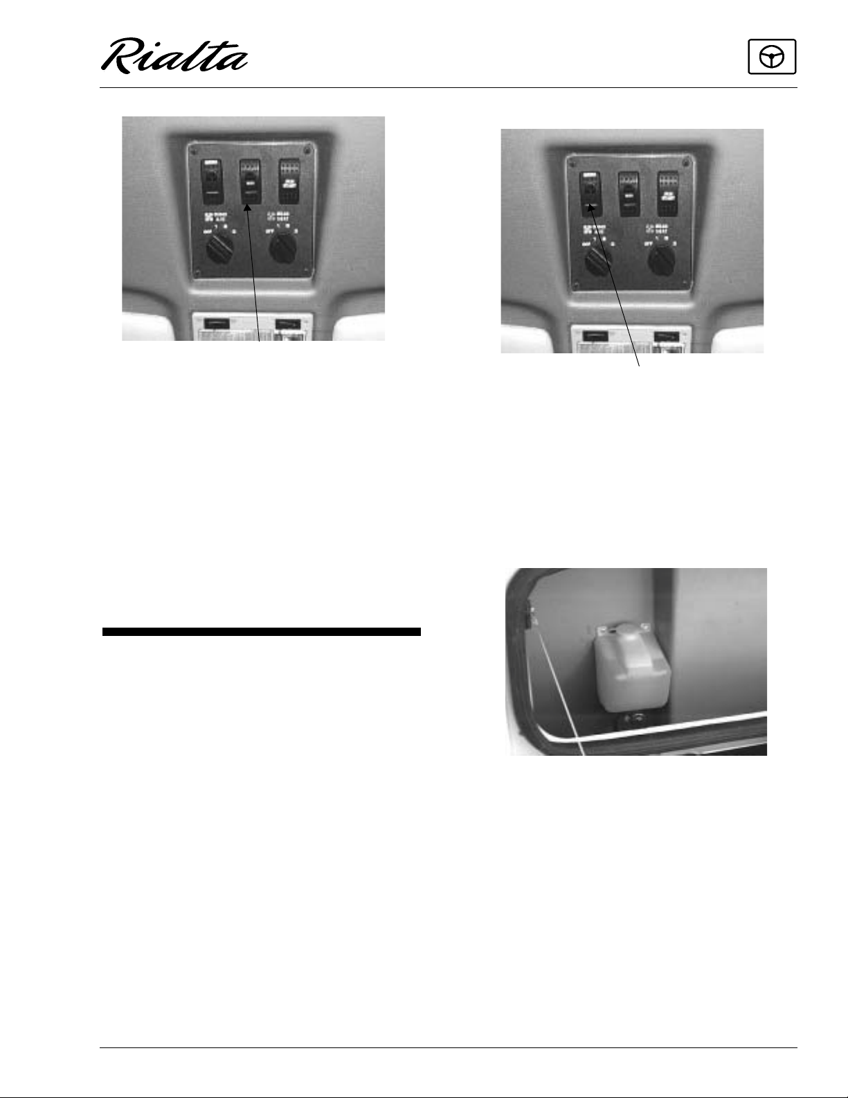
REAR WIPER/WASHER (Optional)
The optional rear window wiper/washer is
controlled by a single-speed rocker switch on the
overhead console in the headliner above the rearview mirror. To turn the wiper on or off, press the
switch and release.
Rear Wiper/Washer Switch
To use the rear washer, press and hold the
switch for as long as needed. The washer will
stop when you release the switch. The wiper will
continue until you turn the switch off.
The rear washer fluid reservoir is located in
the trunk compartment. (See Introduction page
0-4.)
2-9

 Loading...