

Winnebago Minnie (2005) Owner's Manual

OWNER’S NAME
STREET ADDRESS
CITY AND STATE (OR PROVINCE IN CANADA)
MOTOR HOME SERIAL NUMBER
VEHICLE CHASSIS IDENTIFICATION NO. (VIN)
DATE OF DELIVERY TO FIRST RETAIL PURCHASER
VEHICLE MILEAGE AT TIME OF DELIVERY
SELLING DEALER NAME AND ADDRESS
EMERGENCY INFORMATION
YOUR WINNEBAGO INDUSTRIES DEALER
Name ____________________________________________________________________________
Address __________________________________________________________________________
_________________________________________________________________________________
Contact Person _____________________________________________________________________
Phone ____________________________________________________________________________
CHASSIS DEALER/SERVICE CENTER
Name ____________________________________________________________________________
Address __________________________________________________________________________
_________________________________________________________________________________
Contact Person _____________________________________________________________________
Phone ____________________________________________________________________________
INSURANCE POLICY
Company _________________________________________________________________________
Policy Number _____________________________________________________________________
Phone ____________________________________________________________________________
September 2007 132000-03-005

2005 NEW VEHICLE LIMITED WARRANTY
WINNEBAGO INDUSTRIES, INC.
WARRANTY COVERAGE TO OWNER
Winnebago Industries, Inc. of Forest City, Iowa warrants each new
Winnebago Industries motor home to the owner for use in the U.S.A.
and Canada as follows:
WARRANTY PERIOD
The Warranty Period for all coverages begins on the date the vehicle
is delivered to the first retail purchaser or first placed in service as a
demonstrator or company vehicle.
BASIC COVERAGE
The basic Warranty Period is 12 months or 15,000 miles (24,135
kilometers), on the odometer, whichever occurs first. Winnebago
Industries does not authorize any person to create for it any other
obligations or liability in connection with this vehicle. ANY IMPLIED
WARRANTY OF MERCHANTABILITY OR FITNESS FOR A
PARTICULAR PURPOSE APPLICABLE TO THIS VEHICLE IS
LIMITED IN DURATION TO THE DURATION OF THIS WRITTEN
WARRANTY AS HEREINBEFORE OR HEREINAFTER PROVIDED.
THE PERFORMANCE OF REPAIRS IS THE EXCLUSIVE REMEDY
UNDER THIS WRITTEN WARRANTY OR ANY IMPLIED
WARRANTY. WINNEBAGO INDUSTRIES SHALL NOT BE LIABLE
FOR INCIDENTAL OR CONSEQUENTIAL DAMAGES FOR LOSS
OF TIME, INCONVENIENCE, OR OTHER CONSEQUENTIAL
DAMAGE INCLUDING EXPENSE FOR GASOLINE, TELEPHONE,
TRAVEL, LODGING, LOSS OR DAMAGE TO PERSONAL
PROPERTY, OR LOSS OF REVENUE RESULTING FROM
BREACH OF THIS WRITTEN WARRANTY OR ANY IMPLIED
WARRANTY. Some states do not allow limitations on how long an
implied warranty will last or the exclusion or limitation of incidental or
consequential damages, so the above limitations or exclusions may
not apply to you.
ITEMS NOT SUBJECT TO WARRANTY COVERAGE.
Chassis, Drivetrain and related components*
Wheels*
Tires*
Service Items, such as Windshield Wiper Blades, Lubricants, Fluids
& Filters
Adjustments
*These items are covered under the manufacturer’s individual
warranty.
This warranty gives you specific legal rights and you may also have
other rights which vary from state to state.
Also, this warranty shall not apply to failures, damage or
malfunctions resulting from normal wear, misuse, abuse, negligence,
alteration, accident, fire, improper repair of the vehicle or failure to
follow recommended maintenance requirements.
36 MONTHS/36,000 MILE STRUCTURAL WARRANTY
At the expiration of the Basic Coverage and for the remainder of the
period of 36 months or 36,000 miles (57,924 kilometers), on the
odometer, whichever occurs first, Winnebago Industries warrants the
following:
1. Body Thermo-Panel
against delamination. Body Thermo-Panel
bonding of the exterior skin and the interior paneling to an
insulating core material. Delamination (separation of layers)
caused by other factors such as physical damage or failure to
properly maintain sealants is not covered by this warranty.
2. The slide-out room assembly for defects in material or
workmanship.
3. Structural defects of the subfloor and floor. Floor lamination
failure and lamination failure of the subfloor panels and risers
are covered by the structural warranty.
®
Lamination of the sidewalls and backwall
®
Lamination is the
WINNEBAGO INDUSTRIES’ RESPONSIBILITY
Any part of the vehicle subject to warranty which is found to be
defective in material or workmanship, will be repaired or replaced at
Winnebago Industries’ option upon notice of the defect without
charge to the customer for parts or labor. While any Winnebago
Industries motor home dealer can perform warranty service, we
recommend you return to the dealership that sold you your vehicle. If
you are touring or have moved, contact any Winnebago Industries
motor home dealer in the United States or Canada for warranty
service.
CUSTOMER RESPONSIBILITY WHEN REPAIRS ARE NEEDED
If a part of the system covered by this warranty fails to function or
requires service during the warranty period:
1. Promptly take the vehicle to the selling dealer for repair or
inspection.
2. Written notice of defects must be given to the selling dealer or
manufacturer no later than 10 days after the expiration of the
warranty.
3. If the dealer is incapable of making the repairs, request that he
contact Winnebago Industries, Inc.
4. If, after the above steps are completed and the repair is not
made, the customer should contact Winnebago Industries, Inc.,
P.O. Box 152, Forest City, Iowa 50436, Attention: Owner
Relations Department (800-537-1885) and furnish the following
information:
− The complete serial number of the vehicle
− Date of retail purchase
− Selling dealer’s name
− Nature of the service problem, and a brief explanation of the
steps or service the dealer has performed, and the results
obtained. The customer may be directed to another dealer
or service center for repairs to be completed, if such a
dealer or service center is better able to complete the
repair.
Winnebago Industries may, at its option, request the vehicle be
returned to Forest City, Iowa for repair. If the customer refuses to
allow repairs to be performed at the Forest City, Iowa facility, the
warranty on that repair will be voided.
5. If after the above steps are completed and the repairs are not
satisfactory, the customer may contact the Service
Administration Manager of Winnebago Industries, and request a
customer relations board meeting to resolve the problem. This
action, however, is not mandatory.
6. Certain components are covered beyond the 12 months/15,000
miles basic warranty coverage by the individual manufacturer’s
warranty. Please refer to the component’s information supplied
in the owner’s information InfoCase for any additional warranty
coverage after the basic warranty has expired.
DEALER’S REPRESENTATIONS EXCLUDED
Winnebago Industries, Inc. does not undertake the responsibility to
any purchaser of its products for any undertaking, representation, or
warranty made by dealers selling its product beyond those herein
expressed.
INSTALLATION NOT COVERED
Winnebago Industries, Inc. cannot , however, and does not accept
any responsibility in connection with any of its motor homes for
additional equipment or accessories installed at any dealership or
other place of business, or by any other party other than Winnebago
Industries, Inc. Such installation of equipment or accessories by any
other party will not be covered by the terms of this warranty.
CARE AND MAINTENANCE
It is the owner’s responsibility to perform the care, maintenance and
proper load distribution described in the owner’s manual which

accompanies your motor home. Any damage which results to your
vehicle as a result of your failure to perform such duties, is not
covered.
Damage to appearance items such as fiberglass, metal, paint,
fabrics and trim, may occur during manufacturing or transporting.
Normally, any factory defect or damage is corrected at the factory. In
addition, dealers are obligated to inspect each vehicle upon delivery
to them and prior to delivery to you. You should also immediately
inspect appearance items and advise your selling dealer of any
discrepancies. Damage and normal deterioration due to use and
exposure is not covered by this warranty.
CHANGES IN DESIGN
Winnebago Industries, Inc. reserves the right to make changes in
design and changes or improvements upon its products without
imposing any obligation upon itself to install the same upon its
products theretofore manufactured.
NEW YORK:
If your motor home has been repaired three or more times for the
same nonconformity, defect, or condition, or if your motor home has
been out of service by reason of repair for twenty-one days, Section
198-a of the General Business Law of the State of New York requires
you to provide written notice by certified mail, return receipt
requested, to Winnebago Industries or its authorized dealer before
making any claim under that section of the law. If you do have
problems with your motor home, you should provide written notice to
Winnebago Industries at the following address:
Winnebago Industries, Inc.
P.O. Box 152
Forest City, Iowa 50436
Atten: Owner Relations

TABLE OF CONTENTS
Section One ................................................................................................... Specifications
Section Two ..................................................................................................... Introduction
Section Three.............................................................. Getting to Know Your Motor Home
Section Four .......................................................................................Roadside Emergency
Section Five.........................................................................................................Dash/Auto
Section Six................................................................................... Appliances & Equipment
Section Seven .......................................................................... Heating & Air Conditioning
Section Eight ............................................................................................... LP Gas System
Section Nine ............................................................................................. Electrical System
Section Ten............................................................................................. Plumbing Systems
Section Eleven............................................................................................... Entertainment
Section Twelve.................................................................................Furniture & Softgoods
Section Thirteen ...........................................................................................Slideout Room
Section Fourteen..................................................................................Care & Maintenance
Section Fifteen.......................................................................................................... Chassis
SECTION 1 SPECIFICATIONS
TANK CAPACITIES
Chassis Fuel Tank
22’ models only ...............................................................................................37 gal.
All models 24’ or longer..................................................................................55 gal.
LP Gas Tank
All Models ...............................................................................14 gal.* (18 gal. w.c.)
Fresh Water Tank
Models 322E & 322R ......................................................................................28 gal.
Model 324F......................................................................................................32 gal.
Models 324V & 326A......................................................................................38 gal.
Models 327L, 329B & 329K ...........................................................................39 gal.
Models 331C & 332G......................................................................................31 gal.
1 - SPECIFICATIONS
Water Heater - All Models ..............................................................................6 gal.
HT1 - Black Water Holding Tank
Models 329B, 329K & 332G (Toilet) ..............................................................31 gal.
Model 322E (Toilet & Lavatory) .....................................................................39 gal.
Model 322R (Toilet & Lavatory).....................................................................32 gal.
Models 324F, 324V & 326A (Toilet & Lavatory) ...........................................39 gal.
Models 327L (Toilet) .......................................................................................31 gal.
Model 331C (Toilet & Lavatory).....................................................................36 gal.
HT2 - Gray Water Holding Tank
Model 327L, 329B, 329K & 332G (Galley, Shower & Lavatory) ................. 39 gal.
Model 322E (Galley & Shower)......................................................................32 gal.
Model 322R (Galley & Shower)......................................................................39 gal.
Model 324F, 324V & 326A (Galley & Shower)..............................................30 gal.
Model 331C (Galley & Shower)......................................................................29 gal.
*LP Gas tank capacity shown is the usable “full” LP gas capacity, which is 80% of the tank manufacturer’s listed water capacity (w.c. shown in parenthesis). An LP tank must have at least 20% of tank
volume free to allow for expansion and proper vaporization of the liquid fuel. The tank is also equipped
with mandatory safety shut-off equipment that prevents filling above this level.
NOTE: Capacities shown are approximate volumes based on computer design calculations. Usable
capacities may vary according to fabrication and installation of tanks and compartments.
1-1

BODY & CHASSIS SPECIFICATIONS
Model
Length (Bumper to Bumper) 22’ 1” 22’ 1” 24’ 7” 24’ 7” 27’ 1” 27’ 11” 29’ 4” 29’ 4” 31’ 4” 32’ 1”
Interior Width 8’ 0” 8’ 0” 8’ 0” 8’ 0” 8’ 0” 8’ 0” 8’ 0” 8’ 0” 8’ 0” 8’ 0”
Exterior Width 101.5” 101.5” 101.5” 101.5” 101.5” 101.5” 101.5” 101.5” 101.5” 101.5”
Interior Height 6’ 8” 6’ 8” 6’ 8” 6’ 8” 6’ 8” 6’ 8” 6’ 8” 6’ 8” 6’ 8” 6’ 8”
Exterior Height w/AC 11’ 0” 11’ 0” 11’ 3” 11’ 5” 11’ 2” 11’ 1” 11’ 2” 11’ 3” 11’ 3” 11’ 4”
Exterior Storage (cu. ft.) 10.7 17.1 35.0 38.0 117.1 19.9 57.6 52.6 39.6 45.5
GCWR (lbs.)
opt
GVWR (lbs.)
opt
GAWR - Front (lbs.) opt 4,600 4,600 4,600 4,600 4,600 4,600 4,600 4,600 4,600 4,600
GAWR - Rear (lbs.)
opt
Wheelbase 138” 138” 158” 158” 158” 182” 190” 190” 220” 215”
322E 322R 324F 324V 326A 327L 329B 329K 331C 332G
18,500 18,500 20,000 18,500-
20,000
10,700 10,700 14,050 11,500-
14,050
7,500 7,500 9,450 7,800
9,450
20,000 20,000 20,000 20,000 20,000 20,000
14,050 14,050 14,050 14,050 14,050 14,050
9,450 9,450 9,450 9,450 9,450 9,450
NOTE: The height of each model is based on the curb weight of a typically equipped unit and is measured to the highest standard feature on the roof. The actual height of a vehicle may vary by several
inches depending on equipment variations.
1-2

SECTION 2 INTRODUCTION
IMPORTANT: Before driving your vehicle, be
sure you have read the entire operator’s manual
and that you understand your vehicle’s equipment completely and how to use the equipment
safely.
NOTE: The descriptions, illustrations, and
specifications in this manual were
correct at the time of printing. We
reserve the right to change specifications
or design without notice, and without
incurring obligation to install the same
on products previously manufactured.
Congratulations! We welcome you to the exciting world of motor home travel and camping.
You will find it convenient and enjoyable to have
all the comforts of home and still enjoy the great
outdoors wherever you choose to go.
Your motor home has been carefully designed, engineered and manufactured to provide
dependability as well as safety. Before sliding
into the driver’s seat, please become familiar
with operations and features. This manual was
prepared to aid you in the proper care and operation of the vehicle and equipment. We urge you
to read it completely. In addition, spend some
time with the dealer when you take delivery, you
will want to learn all you can about your new motor home.
Read and understand all instructions and precautions in this manual before operating your
new motor home.
ual are intended as a guide, and in no way extend
the responsibilities of Winnebago Industries
beyond the standard written warranty as presented in this manual.
Please read this operator’s manual completely
to understand how everything in your coach
works before taking it on its “maiden voyage.”
This manual is a guide to safe operation of the
features, equipment and controls in this coach.
Some equipment, such as the vehicle chassis and
certain electronic systems or appliances, have
their own comprehensive, manufacturer supplied
manuals or information sheets which describe
the operation of these products in great detail.
This manual will refer you to the manufacturer’s
information included in your Owner InfoCase
whenever necessary.
We also urge you to read the complete
Chassis Operating Guide provided by the
chassis maker and all other operating information provided by our equipment suppliers
and manufacturers. This is contained in your
Owner InfoCase.
This manual should be kept in the vehicle at
all times for personal reference. The operator’s
manual, InfoCase and chassis operating guide
are to be considered permanent components of
this vehicle. They should remain in the vehicle
when sold to provide the next owner with important safety, operating and maintenance information.
2 - INTRODUCTION
ABOUT THIS MANUAL
This manual describes many features of your
motor home and includes instructions for its safe
use. This manual, including photographs and
illustrations, is of a general nature only. Some
equipment and features described or shown in
this manual may be optional. Because of Winnebago Industries’ continuous program of product improvement, it is possible that recent
product changes and information may not be
included. The instructions included in this man-
SAFETY MESSAGES USED IN THIS
MANUAL
Throughout this manual, certain items are
labeled Note, Caution, Warning or Danger.
These terms alert you to precautions that may
involve damage to your vehicle or a risk to your
personal safety. Read and follow them carefully.
2-1
SECTION 2
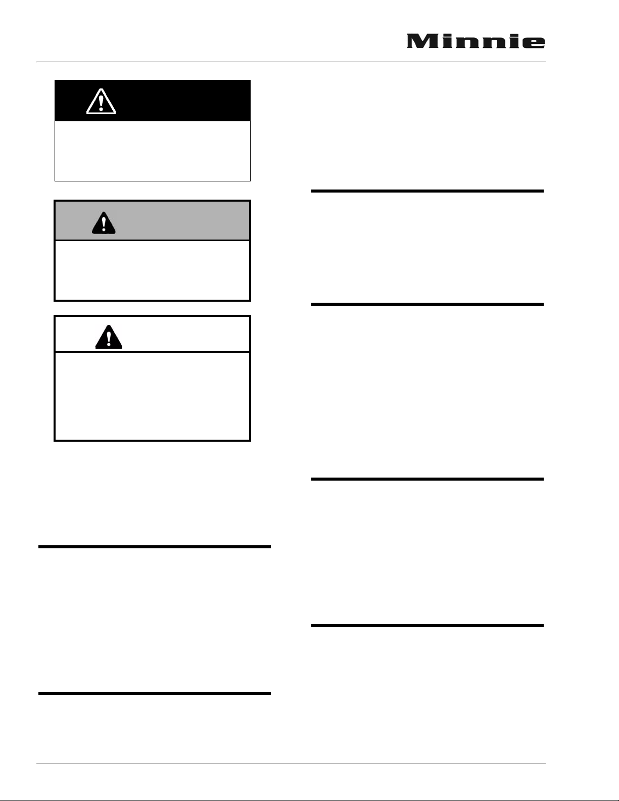
DANGER
WARNING
INTRODUCTION
DANGER indicates a directly hazardous situation which, if not avoided,
will result in death or serious personal
injury.
.
WARNING indicates a potentially
hazardous situation which, if not
avoided, could result in death or serious personal injury.
CAUTION
CAUTION indicates a potentially
hazardous situation which, if not
avoided, could result in damage
mainly to equipment or property, but
in some cases may also result in
minor or moderate personal injury.
maintenance instructions for the various appliances and components in your motor home.
Warranty registration cards for these items
should be filled out and mailed as soon as possible after you take delivery of your motor home.
If you do not have operating instructions for a
particular appliance, contact your dealer.
OPTIONS AND EQUIPMENT
This model is available in several sizes and
floorplans, so accessories and components may
differ slightly between models. Some equipment
described in this manual may not apply to your
coach.
PRE-DELIVERY INSPECTION
This motor home has been thoroughly inspected before shipment. Your dealer is responsible
for performing a complete pre-delivery inspection of the chassis and all motor home components.
As a part of the pre-delivery inspection procedure, the dealer is responsible for road testing the
motor home; noting and correcting any problems
before delivery.
NOTE: A ‘Note’ is not necessarily safety related
but indicates a recommendation or special point of information that could assist
in understanding the use or care of a feature item.
CHASSIS OPERATING GUIDE
Throughout this manual, frequent reference
is made to the vehicle chassis operating guide.
The chassis guide is the operator’s manual
provided by the manufacturer of the chassis on
which this motor home is built (i.e., Ford). Consult the chassis guide for operating safety and
maintenance instructions pertaining to the chassis section of the motor home.
OWNER INFOCASE
The materials in your Owner InfoCase con-
tain warranty information and operating and
FRONT AXLE TIRE ALIGNMENT
We recommend that you have the front suspension and steering alignment checked and adjusted after you have fully loaded the vehicle
according to your needs. Thereafter, have alignment inspected periodically to maintain vehicle
steering performance and prevent uneven tire
wear.
BEFORE DRIVING
Before sitting in the driver’s seat, always
check around your vehicle to be sure you have
proper clearance for maneuvering. If necessary,
have a passenger help guide you out of a difficult
parking space.
Although your coach features automotive
conveniences like power steering and power
2-2

SECTION 2
INTRODUCTION
brakes, driving a motor home is different from
driving a car. A motor home is larger and heavier
than an automobile, so it requires more stopping
and passing distance, and more parking and maneuvering space than does a car.
Always be aware of the size of your motor
home. The added height of roof air conditioners,
TV antennas or luggage boxes may cause clearance problems around some tunnels, canopies
and hanging signs. Know the height of your unit
so you can observe posted clearance limits.
Remember: Always use your seat belt and be
sure your passengers do so as well.
SERVICE AND ASSISTANCE
Your dealer will be glad to provide any additional information you need, as well as answer
any questions you might have about operating the
equipment in your motor home. When it comes to
service, remember that your dealer knows your
vehicle best and is interested in your satisfaction.
Your dealer will provide quality maintenance and
any other assistance that you may require during
your ownership of this vehicle.
If you need warranty repairs while traveling
you may take your motor home to any authorized
Winnebago or Itasca dealership and request their
assistance.
See the dealership directory in your Owner
InfoCase.
(NHTSA) in addition to notifying Winnebago Industries, Inc.
If NHTSA receives similar complaints, it may
open an investigation, and if it finds that a safety
defect exists in a group of vehicles, it may order
a recall and remedy campaign. However, NHTSA cannot become involved in individual problems between you, your dealer, or Winnebago
Industries.
To contact NHTSA, you may either call the
Auto Safety Hotline toll-free at 1-800-424-9393
(or 366-0123 in Washington, D.C. area) or write
to: NHTSA, U.S. Department of Transportation,
Washington, D.C. 20590. You can also obtain
other information about motor vehicle safety
from the Hotline.
2 - INTRODUCTION
WARRANTY
Your new vehicle is covered by a factory warranty against defects in material and workmanship. This warranty should be validated
immediately and returned to the factory by your
dealer. For additional information, see your
“New Vehicle Limited Warranty” included at the
front of this manual.
REPORTING SAFETY DEFECTS
If you believe that your vehicle has a defect
which could cause a crash or could cause injury
or death, you should immediately inform the National Highway Traffic Safety Administration
2-3
SECTION 2
INTRODUCTION
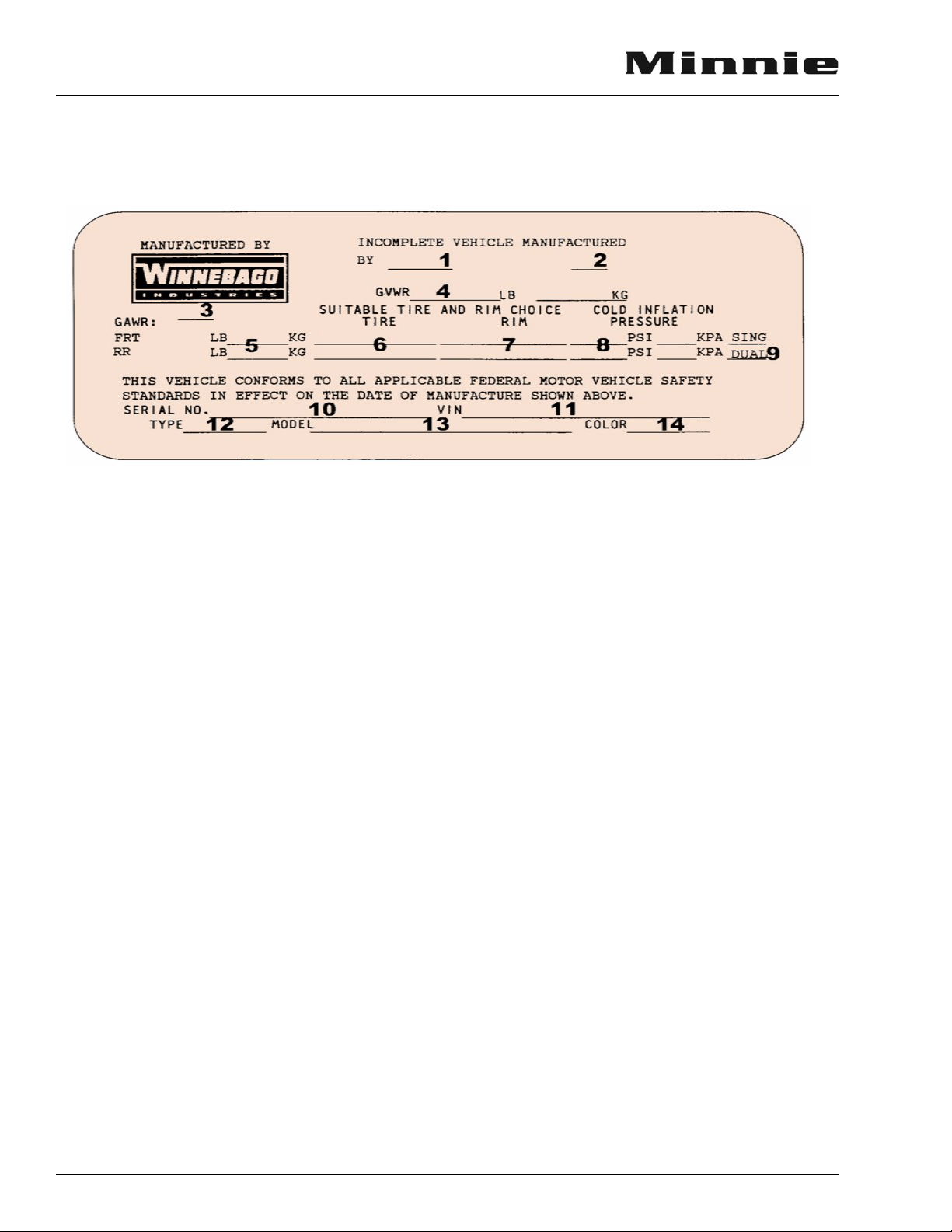
VEHICLE CERTIFICATION LABEL
This label contains vehicle identification and other important reference information. This label is
affixed to the lower inside panel of the driver door or on the door jamb.
Explanation of Data
1. Chassis manufacturer.
2. Chassis manufacture date.
3. Month and year of manufacture at Winnebago Industries.
4. Gross Vehicle Weight Rating: Total permissible weight of the vehicle, including driver,
passengers, total cargo carried (including all
liquids) and equipped with all options.
5. Gross Axle Weight Rating: Total permissible
weight allowed for the front and rear axles
(listed in pounds and kilograms).
6. Suitable Tire Choice: Tires recommended to
meet handling and safety requirements.
When replacing any of the tires on your
vehicle, always replace with a tire that meets
these specifications.
7. Suitable Rim Choice: Wheel rims recommended to meet handling and safety requirements. When replacing any of the rims on
your vehicle, always replace with a rim that
meets these specifications.
8. Cold Inflation Pressure: Inflation pressures
at Gross Axle Weight Ratings recommended
(while Cold) for the tires originally equipped
on your vehicle. These pressure levels must
be maintained to assure proper handling,
safety and fuel economy.
9. Rear Axle Wheel Configuration: Single or
Dual.
10. Serial Number: This is the serial number
assigned to the completed vehicle by Winnebago Industries.
11. Vehicle Identification Number (VIN): This
number identifies the chassis on which the
motor home is built. The 10th digit of the
VIN designates the chassis model year.
(4=2004, 5=2005, etc.). This information is
useful when ordering chassis repair parts.
12. Type: States the NHTSA designated usage
classification for your motor home. MPV
signifies a Multi-purpose Passenger Vehicle.
13. Model: Lists the Winnebago product model
number of your vehicle.
14. Color: Signifies the color code number of the
decor used throughout the vehicle. This
number is necessary for ordering replacement cushions, curtains, carpet, etc.
2-4
SECTION 3 GETTING TO KNOW YOUR MOTOR HOME
WARNING
WARNING
Read and understand all instructions and precautions in this manual before operating your
new motor home.
GENERAL WARNINGS
• Only seats equipped with seat belts are to be
occupied while the vehicle is moving.
• Make sure all passengers have seat belts
fastened in a low and snug position so the
force exerted by the belt in a collision will be
spread across the strong hip area. Pregnant
women should wear a lap-shoulder belt
whenever possible, with the lap belt portion
worn low and snug throughout the
pregnancy.
• All moveable or swiveling seats should be
placed and locked in forward facing positions
while the vehicle is moving.
• Never let passengers stand or kneel on seats
while the vehicle is moving.
• Sleeping facilities are not to be utilized while
vehicle is moving.
• Examine the escape window and be familiar
with its operation.
• Ιnspect the fire extinguisher monthly for
proper charge and operating condition. This
should also be done before beginning a vacation or any extended trip.
DRIVING
• Driving through water deep enough to wet
the brakes may affect stopping distance or
cause the vehicle to pull to one side. Check
brake operation in a safe area to be sure they
have not been affected. Never operate any
vehicle if a difference in braking efficiency is
noticeable.
• Adverse weather conditions and extremes in
terrain may affect handling and/or performance of your vehicle. Refer to your chassis
manual for related information.
FORMALDEHYDE INFORMATION
Some components in this vehicle contain formaldehyde based adhesives
which may release formaldehyde
fumes into the air for an unknown
period of time until total dissipation
occurs. Individuals who are allergic
to formaldehyde gas fumes may
experience irritation to eyes, ears,
nose and throat. Reaction in infants
may be more severe. Although long
range effects are not well understood,
testing to date has not revealed any
serious health effects in humans at the
level of emission from these products.
3 - GETTING TO KNOW YOUR MOTOR HOME
• Do not attempt to adjust the driver’s seat
while the vehicle is moving.
• Do not adjust tilt steering in a moving vehicle.
• Do not operate the cruise control on icy or extremely wet roads, winding roads, in heavy
traffic, or in any other traffic situation where
a constant speed cannot be maintained.
• Use care when accelerating or decelerating
on a slippery surface. Abrupt speed changes
can cause skidding and loss of control.
CARBON MONOXIDE WARNING
Avoid inhaling exhaust gases, as they
contain carbon monoxide, which is a
colorless, odorless and poisonous gas.
3-1
SECTION 3
WARNING
GETTING TO KNOW YOUR MOTOR HOME
The best protection against carbon monoxide
entry into the vehicle body is a properly maintained engine exhaust and ventilation system. It is
recommended that the exhaust system and body
be inspected by a qualified motor home service
center.
• Each time the vehicle is serviced for an oil
change.
• Whenever a change in the sound of the
exhaust system is noticed.
• Whenever the exhaust system, underbody or
rear of the vehicle is damaged.
To allow proper operation of the vehicle’s
ventilation system, keep front ventilation inlet
grill clear of snow, leaves or other obstructions at
all times. DO NOT OCCUPY A PARKED
VEHICLE WITH ENGINE RUNNING FOR
AN EXTENDED PERIOD.
Do not run engine in confined areas, such as a
garage, except to move vehicle into or out of
area.
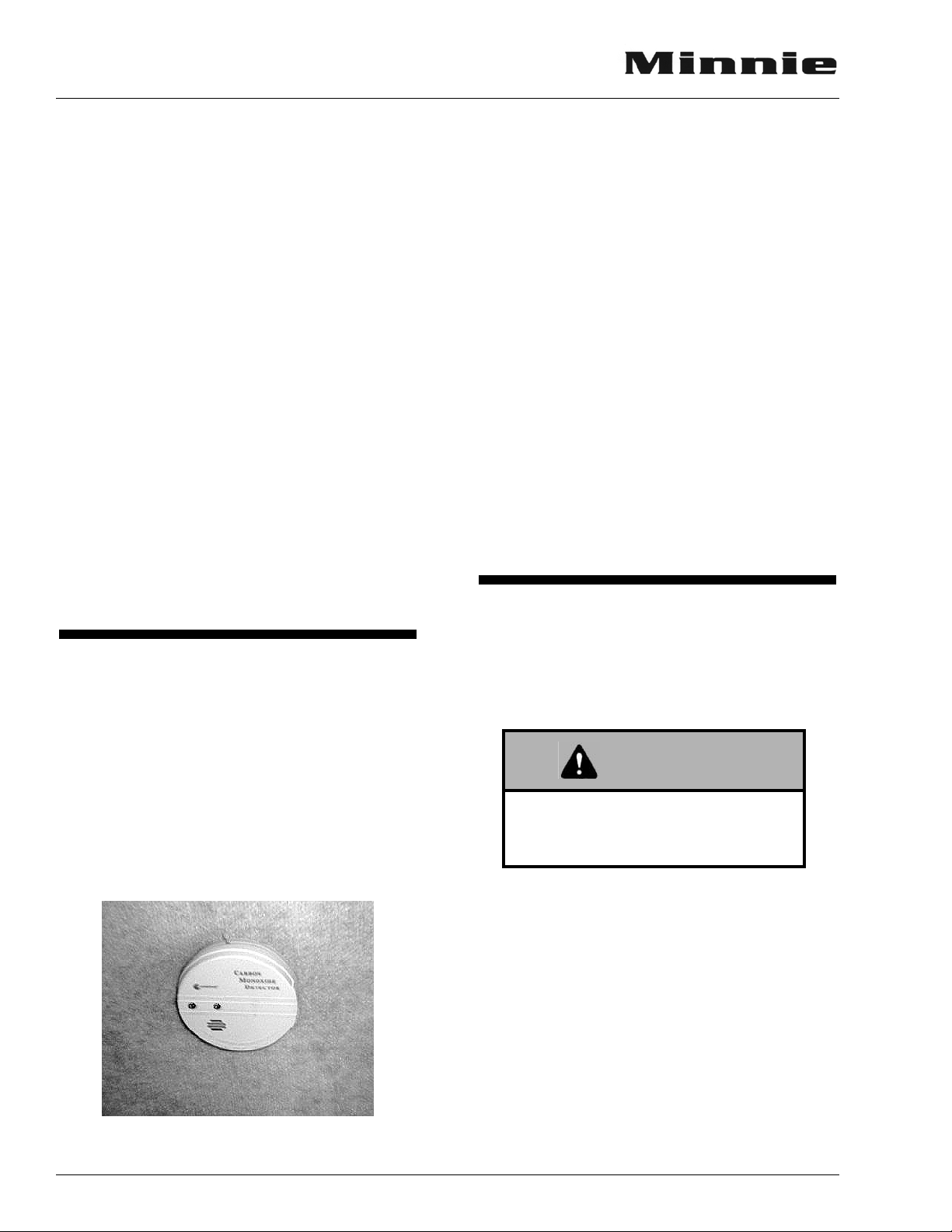
CARBON MONOXIDE ALARM
Your coach is equipped with a carbon monoxide (CO) alarm located on the ceiling in the bedroom area. The CO alarm is powered by a 9-volt
battery and has a sensor that is designed to detect
toxic carbon monoxide gas fumes resulting from
incomplete combustion of fuel. It will detect CO
gas from any combustion source such as the furnace, gas range/oven, water heater, refrigerator,
chassis engine, and electric generator engine.
Monthly Testing
Press the TEST button on the face of the alarm
at least monthly to check the function of the
alarm and condition of the battery. If the alarm
begins to beep every few seconds, the battery
may be weak and needs replacement. (Press the
TEST button to be sure before replacing the battery. If the alarm sounds, the battery may still be
okay. If the alarm still beeps every few seconds,
check the smoke detector also. The “low battery”
warning beep is similar on many alarm devices,
so the origin of this electronic sound can be deceiving.)
Further Information
Please read the information provided by the
manufacturer, which is included in your Owner
InfoCase. It includes information on precautions,
operational testing, and battery/sensor replacement.
EMERGENCY EXITS
Instructions for operation are also located on a
label on the glass for quick reference and for passengers who may not be familiar with the exit.
Never remove or destroy this label.
Use care when exiting emergency
window, as broken glass may be
present in the exit area.
3-2
Carbon Monoxide Alarm
Swing-Out Side Escape Window
The bedroom side escape window is secured
by two red safety latches at the bottom of the
window.
To open, lift both latches up and toward the
center of the window, then push outward near the
bottom of the window.
Instructions for opening are also located near
the latches for quick reference and for passengers
who may not be familiar with the exit. Never
remove or destroy this label.
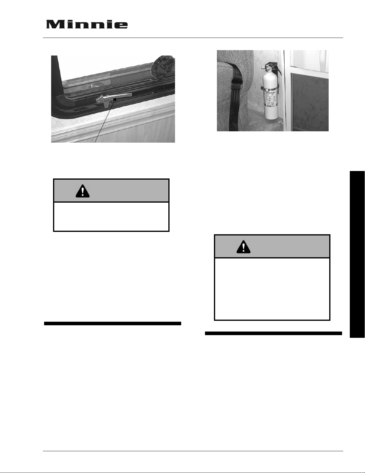
Lift latch handles upward to open.
WARNING
WARNING
Escape Window
This window should be kept closed
while driving to avoid drawing dangerous exhaust gases into the vehicle.
SECTION 3
GETTING TO KNOW YOUR MOTOR HOME
We recommend that you become thoroughly
familiar with the operating instructions displayed
on the side of the fire extinguisher or in the information supplied in your Owner InfoCase.
We also recommend that you inspect the fire
extinguisher for proper charge at least once a
month in accordance with National Fire Protection Association (NFPA) recommendations as
stated on the label.
If the charge is insufficient, the fire extinguisher must be replaced.
Using Slider Windows As Emergency
Exits
Most slider windows along the side of the
motor home can also be used as emergency exits,
should the need arise. To use the windows as
exits, first slide the window open, then slide the
screen open or push the screen material out,
depending on window type.
FIRE EXTINGUISHER
A dry chemical fire extinguisher is located
near the main entrance door.
Do not test the fire extinguisher by
discharging it. Partial discharge can
cause leakage of pressure or contents
which would render the unit inoperative when needed. When using the
fire extinguisher, aim the spray at the
base of the fire.
3 - GETTING TO KNOW YOUR MOTOR HOME
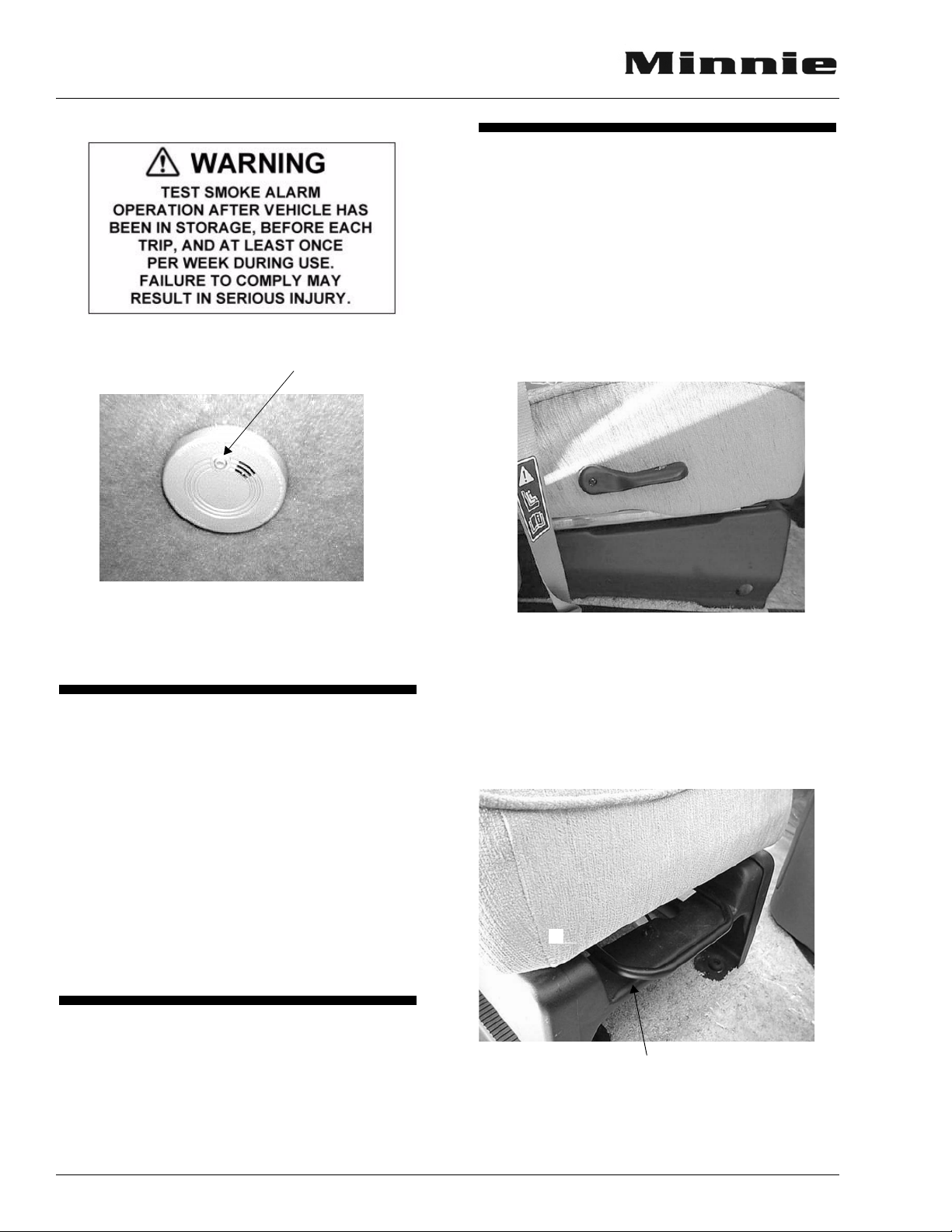
SMOKE ALARM
Your motor home is equipped with a smoke
alarm located on the ceiling in the galley area.
This alarm meets U.L. Standard 217 and NFPA
Standard 74 for operation of smoke detection
devices.
The following label is affixed either to the
smoke alarm or on the ceiling near the smoke
alarm.
3-3
SECTION 3
GETTING TO KNOW YOUR MOTOR HOME
Press button to test
SEATS
The driver and co-pilot seats may be indepen-
dently adjusted to suit individual preference.
To Recline the Seats
Lift the reclining lever, lean back to desired
incline and release the lever. To return to the upright position, lift the lever and lean body forward. Allow the seat to return to the desired
position and release the lever.
Smoke Alarm
See your Owner InfoCase for further informa-
tion.
KEYS
Your motor home is supplied with several sets
of keys. In addition to the chassis manufacturer's
ignition key, you receive keys for the entrance
door and exterior compartment doors.
Keys have an identification number, either a
small metal tag or stamped into the key head.
These numbers are recorded on the vehicle’s
component model/serial sheet which is included
in your owner InfoCase. In case keys are lost or
stolen, your dealer or a locksmith can provide
you with duplicate keys or modify the locks.
KEYLESS ENTRY SYSTEM
(Ford chassis supplied)
The keyless entry system is chassis supplied
for the cab doors.
Seat Recline Lever
To Slide Seat Front-Back
Lift the seat adjustment bar and use body pressure to adjust the forward-rearward position of
the driver seat. Release bar to lock seat in desired
position.
Seat Position Adjustment Bar
(Lift to slide forward - back)
3-4

SECTION 3
WARNING
GETTING TO KNOW YOUR MOTOR HOME
Do not adjust driver’s seat while vehicle is in motion.
After adjusting seat, always use body
pressure to make sure slide and
swivel locking mechanism have
engaged.
If your model has a dinette seat located
directly behind the driver or passenger front seat,
the dinette seat back is hinged and can be folded
down to allow full use of the front seat reclining
feature. Simply remove the seat back cushion and
unlatch the bolt latches on both sides of the
dinette seat as shown, then fold downward.
SEAT BELTS
Seats intended for occupancy while the vehicle is in motion are equipped with seat belts for
the protection of the driver and passengers.
Lap Belts
The lap belts must be worn as low as possible
and fit snugly across the hip area. Always sit
erect and well back into the seat. To gain full protection of the safety belt, never let more than one
person use the same safety belt at any one time,
and do not let the safety belts become damaged
by pinching them in the doors or in the seat mechanism. After any serious accident, any seat belts
which were in use at the time should be replaced.
Dinette Seatback Latch
(Remove cushion and unbolt to fold down
Dinette seat folds down to allow front
seat reclining.
Adjustment: To lengthen belt, turn tongue at a
right angle to belt and pull to desired length.
To shorten, pull loose end of belt.
To Fasten: Be sure belt is not twisted. Grasp
each part of the belt assembly and push
tongue into buckle. Adjust to a snug fit by
pulling the loose end away from the tongue.
3 - GETTING TO KNOW YOUR MOTOR HOME
To Release: Press button in center of buckle and
slide tongue out of buckle.
3-5
SECTION 3
WARNING
WARNING
GETTING TO KNOW YOUR MOTOR HOME
Snug and low belt positions are
essential. This will ensure that the
force exerted by the lap belt in a collision is spread over the strong hip area
and not across the abdomen, which
could result in serious injury.
Only seats equipped with seat belts
are to be occupied while vehicle is in
motion.
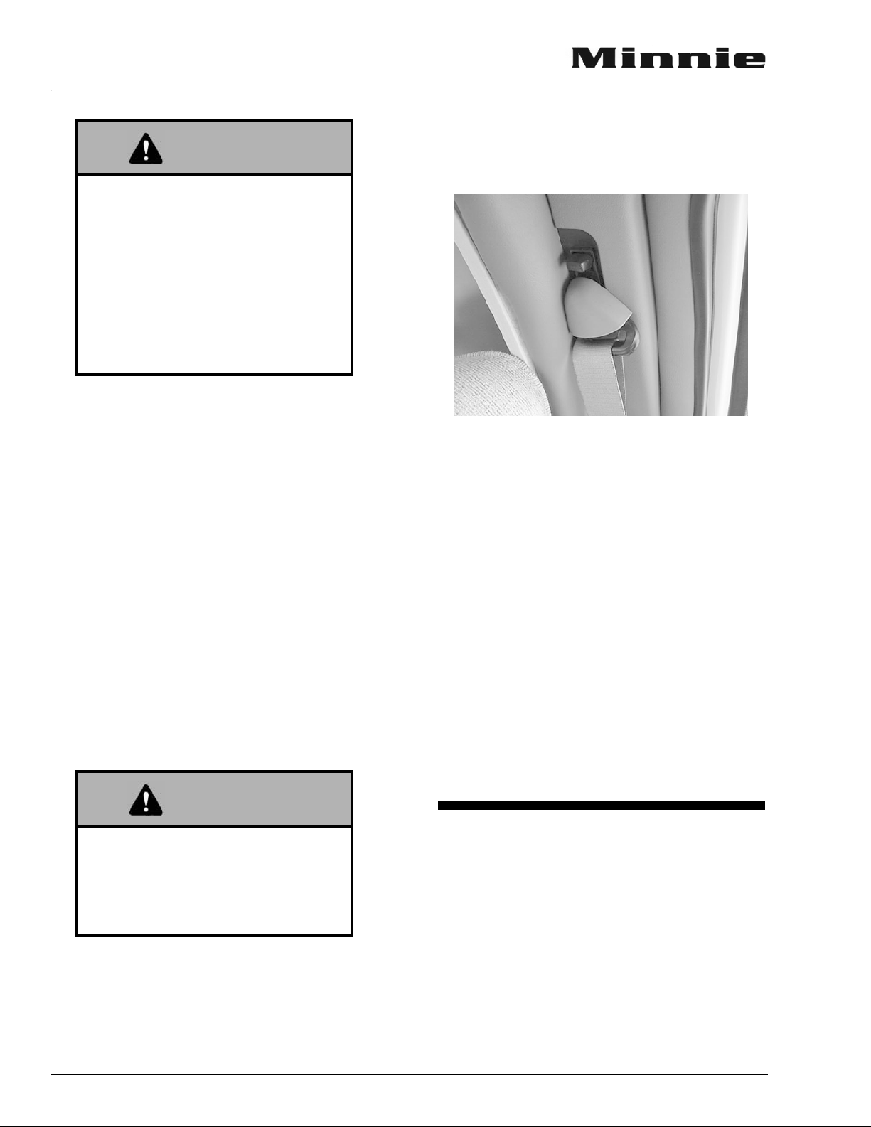
Lap-Shoulder Belts
Fastening: Hold the belt just behind the
tongue using the hand nearest to the door. Next,
bring the belt across the body and insert the
tongue into the buckle until the latch engages.
Unfastening: Press the release button in the
buckle. Hold onto the tongue when you release it
from the buckle to keep it from retracting too rapidly.
When the lap-shoulder belt is in use, the lap
belt must ride low across the hip area and the
shoulder belt must ride diagonally over the shoulder toward the buckle.
The shoulder belt is designed to lock only during a sudden stop, sudden body movement or a
collision. At all other times it will move freely
with the occupant.
position and release the lever. A ratcheting mechanism will allow the belt to be
pushed upward but not pulled downward.
Seat Belt Care and Cleaning
• Be careful not to damage the belt webbing
and hardware. Take care not to pinch them in
the seat or doors.
• Inspect the belts and hardware periodically.
Check for cuts, frays, and loose parts. Damaged parts should be replaced. Do not remove
or modify the belt system.
• Keep belts clean and dry. If the belts need
cleaning, use only a mild soap and water
solution. Do not use hot water. Do not use
abrasive cleaners or bleach. These products
may weaken or damage the belts.
• Replace any belt assembly that was used during a severe impact. Replace the complete assembly even if damage is not apparent.
Never wear the shoulder belt in any
position other than as stated above.
Failure to do so could increase the
chance or extent of injury in a collision
NOTE: On some models, the shoulder belt height
can be adjusted to provide the most comfortable position for each individual person’s size. To adjust shoulder belt height,
press the lever down, select the desired
3-6
CHILD RESTRAINTS
A properly installed and secured child restraint system can help reduce the chance or severity of personal injury to a child in an accident
or during a sudden maneuver. Children may be
injured in an accident if they are not seated in a
properly secured child restraint.
A child restraint system is designed to be secured in a vehicle seat by a lap belt or the lap belt
portion of a lap-shoulder belt. According to accident statistics, children are also safer when prop-
SECTION 3
GETTING TO KNOW YOUR MOTOR HOME
erly restrained in rear seating positions than in
front seating positions.
When purchasing a child restraint system:
1. Look for the label certifying that it meets all
applicable safety standards.
2. Make sure that it will attach to your vehicle
and restrain your child securely and conveniently so that you are able to install it correctly each time it is used.
3. Be certain that it is appropriate for the child's
height, weight and development. The
instructions and/or the regulation label
attached to the restraint typically provides
this information.
4. Review the instructions for installation and
use of the restraint. Be sure that you understand them fully and can install the restraint
properly and safely in your vehicle.
If your coach has a dinette, a child seat tether
anchor loop is located in the floor of the coach
directly behind the forward facing dinette seat.
The dinette table must be in the lowered position
when a child seat is in use.
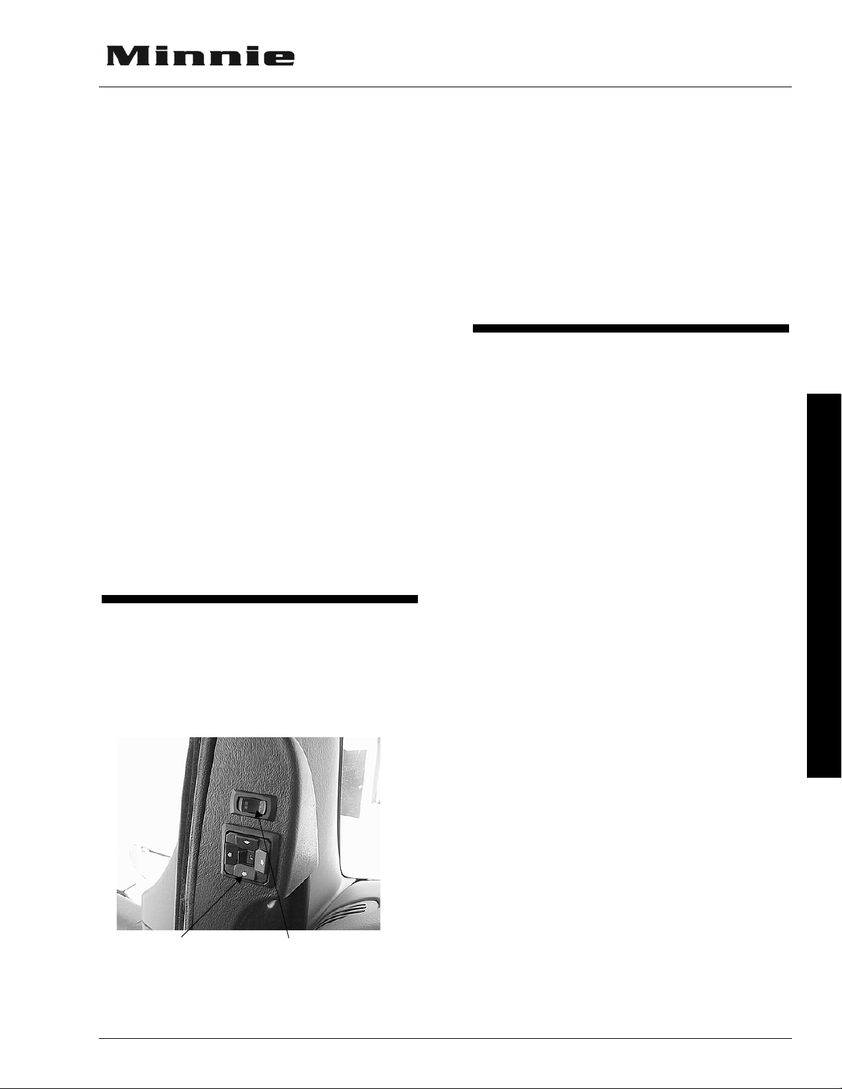
MIRRORS - EXTERIOR
Always adjust mirrors for maximum rear visibility before driving off. Make sure the seat is adjusted for proper vehicle control and that you are
sitting back squarely into the seat.
Mirror Adjustment
Control
Mirror Heat
Switch
Side Mirror Head Adjustment
While sitting properly in the driver seat and
the mirror arms extended normally, have a helper
grip the mirror head by opposite upper and lower
corners and move it horizontally and vertically
for proper rearward vision.
NOTE: For power mirrors, be sure the power
adjustment is in the middle of it’s adjustable range, both up-down and right-left,
before adjusting the head position.
LOADING THE VEHICLE
NOTE: Your motor home’s load capacity is des-
ignated by weight, not by volume, so you
cannot necessarily use all available
space when loading your motor home.
• Store or secure all loose items inside the
motor home before traveling. Possible overlooked items such as canned goods or small
appliances on the countertop, cooking pans
on the range, or free-standing furniture items
can become dangerous projectiles during a
sudden stop or evasive maneuver.
• Be aware of GVWR, GAWR and individual
load limit on each tire or set of duals.
When loading the vehicle, distribute the cargo
load equally so that you do not exceed either the
Front or Rear Gross Axle Weight Rating
(GAWR) or the Gross Vehicle Weight Rating
(GVWR). The Gross Axle Weight Rating
(GAWR) means the weight value specified by
the chassis manufacturer as the load carrying capacity of a single axle system as measured at the
tire-to-ground interfaces. This is the total weight
a given axle is capable of carrying. Each axle has
its own rating.
Have your vehicle weighed to determine the
proper load distribution for your vehicle. Also
distribute cargo side-to-side so the weight on
each tire or dual set does not exceed one half of
the GAWR for either axle.
For example, if the Front GAWR is 6,000 lbs.,
there should be no more than 3,000 lbs. on each
tire. (If the left side weighs 3,100 lbs. and the
3 - GETTING TO KNOW YOUR MOTOR HOME
3-7
SECTION 3
GETTING TO KNOW YOUR MOTOR HOME
right side weighs 2,700 lbs., at least 100 lbs. of
the load should be shifted from the left side to the
right side.) The GVWR is listed on the Vehicle
Certification Label. (See sample in Specifications Section).
The GCWR (Gross Combination Weight Rating) means the maximum allowable loaded
weight of this motor home and any towed trailer
or towed vehicle. If trailer towing is not recommended, the GCWR will equal the GVWR.
NOTE: We recommend that you dump all hold-
ing tanks before traveling to avoid carrying unnecessary weight.
CAUTION
The weight of the loaded vehicle
(including options, attachments, passengers, water, fuel, luggage and all
other cargo) must not exceed the
GVWR or GAWR of either axle.
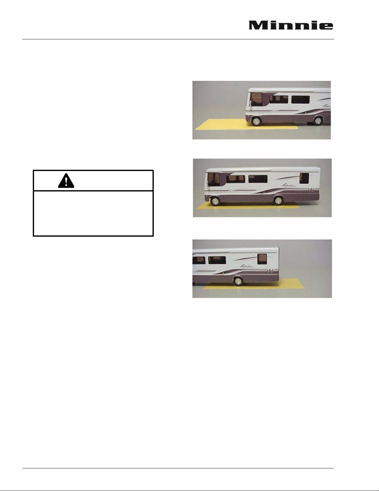
front wheels onto the scale pad, then drive ahead
so that the whole vehicle is on the scale, then
finally pull off until just the rear wheels are on
the pad.
Front GAWR (Front Axle Only)
GVWR (Both Front and Rear Axles)
Weighing Your Loaded Vehicle
To check the weight of your fully loaded
coach, locate a commercial weighing scale that
is capable of weighing large trucks.
Loading: Load your vehicle completely as if
you were going on a long trip, with everything
you would carry, including food, clothing, bedding, lawn chairs, etc., a full fuel tank, full LP
tank, and a partial tank of fresh water - but
empty holding tanks.
Finding a Scale: In urban areas, the most
common places to find a public access scale are
commercial truck stops. In rural areas, most
grain storage elevators have scales available. If
you don’t know of a truck scale in your area,
look in the Yellow Pages for entries such as
Grain Elevators, Scales-Public, Truck Stops,
Weigh Stations, etc. If you cannot locate a scale
in your area, call your state DOT and ask for recommendations. Most scales charge a nominal
fee for weighing a vehicle.
Weighing: There is typically a scale operator to direct you but the basic routine is to take
three separate weights - front axle, whole vehicle, and rear axle. You will first drive only your
Rear GAWR (Rear Axle Only)
You will receive a weight ‘ticket’ that states
your current Front Gross Axle Weight, Rear
Gross Axle Weight and Gross Vehicle Weight.
You can compare these weights to the weight
ratings listed on your Vehicle Certification Label
to use as a guideline for future loading limits and
weight distribution.
The gross weight of the vehicle should not
exceed the Gross Vehicle Weight Rating
(GVWR) specified on the Vehicle Certification
Label. (see section 2). The front and rear axle
weight also should not exceed the corresponding
Axle Weight Rating specified on the Vehicle
Certification Label.
3-8

SECTION 3
GETTING TO KNOW YOUR MOTOR HOME
Corner Weighing (Side-to-Side)
Weighing each corner of the coach separately (single L/R front wheels or L/R rear dual
sets) is an accurate method to determine how to
distribute your cargo to avoid overloading, especially on tires.
To determine the weight distribution on each
tire or dual set, you will need to find a scale
capable weighing side-to-side, or all four ‘corners’ of the vehicle, separately. A truck scale
may be used if the ground is level with the scale
surface and the scale has clearance to drive one
side of the coach onto the scale as shown below.
Drive the coach on the level area next to the
scale and straddle the scale so that only one side
of the coach will be on the scale pad. Pull only
the front wheel onto the pad as shown.
Tires should be filled to the recommended
air pressure for the highest loaded tire set on that
axle. For example, on the rear axle, if the left
side weighs more than the right, fill the left tires
to the pressure required for that weight, then fill
the right tires to the same pressure as the left
ones.
If your actual weight is considerably less
than GAWR rating, you may be able to lower
your tire pressure. See a tire dealer for a load/
pressure chart.
NOTE: The Hitch Load from a Towed Vehicle or
carrier box must also be counted on the
Rear GAWR and subtracted from the
rear axle cargo capacity.
Be aware that hitch load can affect handling
characteristics. The more weight on the hitch, the
lighter the front end will feel at the steering
wheel.
Weighing Left Front ‘Corner’
When the front wheel has been weighed, pull
the coach straight ahead until only the rear
wheel/dual set is on the scale pad as shown.
Weighing Left Rear ‘Corner’
After the rear wheel set has been weighed,
turn the coach around and repeat this process for
the other side.
The load on each wheel or dual-wheel set
should not exceed one-half of the corresponding
GAWR. For example, if the GAWR for the rear
axle is 12,000 lbs., then the load on each rear
dual set (left rear duals or right rear duals)
should not exceed 6,000 lbs.
Roof Loading
The roof is capable of carrying some lightweight articles while the vehicle is in motion. A
roof-mounted luggage carrier designed for this
purpose is available from your dealer. However,
roof load while the vehicle is in motion is not to
exceed 10 pounds per square foot or a maximum
of 100 pounds.
When the vehicle is stationary, a cargo load of
100 pounds plus the weight of a 225 pound person to load the cargo or to conduct inspection and
maintenance is permissible.
Weight added to both the roof and the trailer
hitch contribute to the gross vehicle weight,
which must not exceed the vehicle’s GVWR.
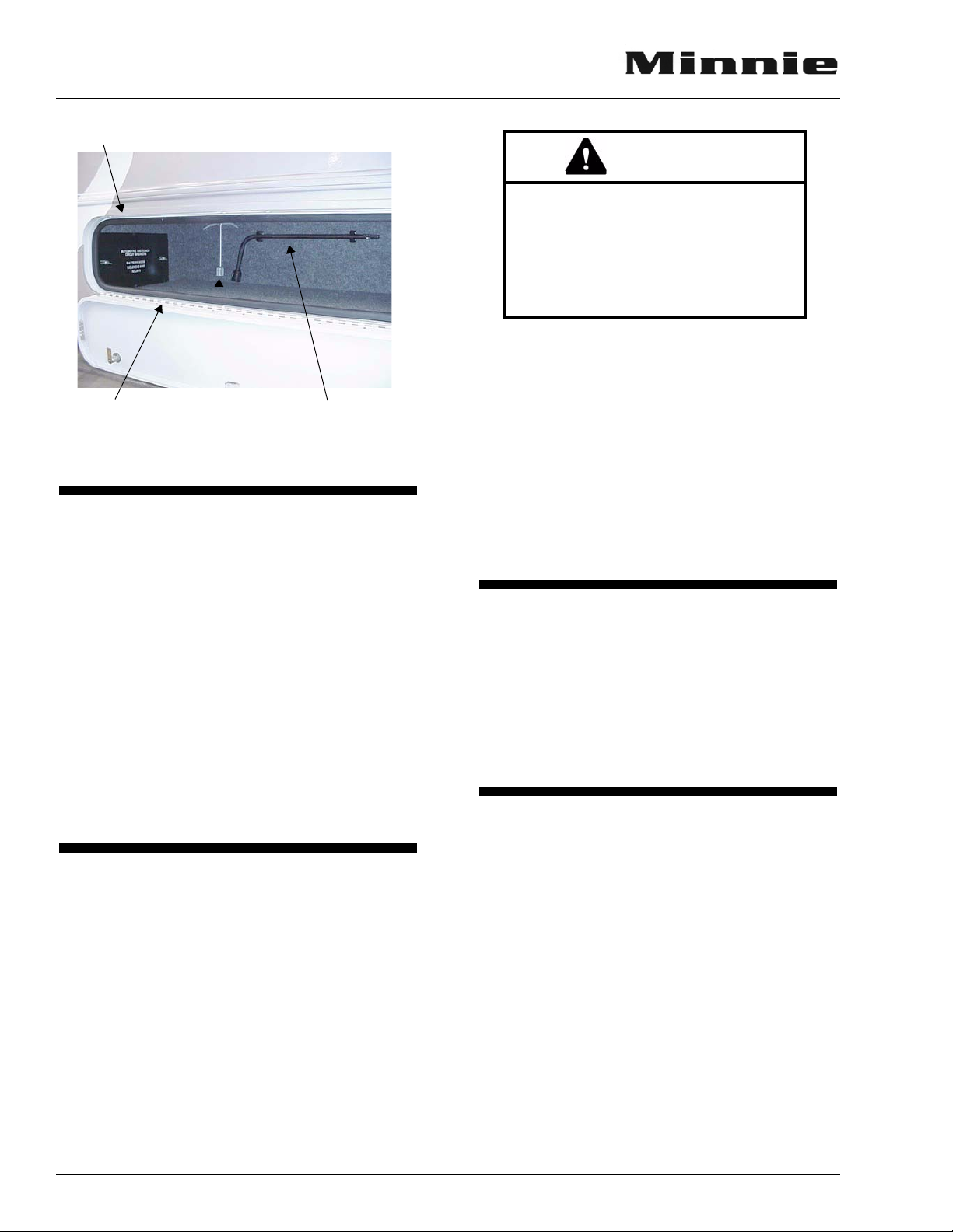
TOOL STORAGE
Various supplied tools are stored in clips on
the walls of one or two of the exterior storage
compartments. Actual locations depend on storage compartment configuration of your model.
The photos following show typical arrangements.
3 - GETTING TO KNOW YOUR MOTOR HOME
3-9
SECTION 3
GETTING TO KNOW YOUR MOTOR HOME
Tire Tools
Awn in g
Stakes
Wheel
Liner Tool
Awning
Hook
STORAGE COMPARTMENT
DOORS
To ensure that exterior storage compartment
doors have latched properly, press firmly on the
bottom edges of the doors with the palms of your
hands. If the door is ajar you will hear and feel a
loud ‘click’ when the latches engage properly.
The high-density gaskets used on the exterior
storage compartments are designed to provide a
more positive seal against dust and weather.
Sometimes this seal firmness can inhibit complete latching of the compartment doors if they
are simply ‘dropped shut’ or closing force is applied only to the center of the door.
MOUNTAIN DRIVING
Special techniques must be used when driving
in mountainous or hilly country.
Climbing A Hill
The transmission will automatically downshift as needed to climb most hills. If the hill is
long or very steep, however, you may need to
manually shift to a lower gear to keep the transmission from repeatedly upshifting and downshifting. Select the lowest adequate gear range
for the duration of the incline. See your chassis
operating guide for specific information.
CAUTION
Observe the engine temperature
gauge more frequently than normal.
If overheating occurs, pull off to the
side of the road and allow the engine
to thoroughly cool before refilling the
radiator and restarting the engine.
Descending A Hill
When going down a long grade, you may need
to manually shift to a lower gear rather than keeping your foot on the brake pedal. A lower gear
will allow the engine to provide a degree of braking action. Holding your foot on the brake pedal
for an extended period may cause brakes to overheat, which could cause you to lose control of the
vehicle. See your chassis operating guide for specific information.
EFFECTS OF PROLONGED
OCCUPANCY
Your motor home was designed primarily for
recreational use and short term occupancy. If you
expect to occupy your coach for an extended period, be prepared to deal with condensation and
humid conditions that may be encountered.
HUMIDITY AND CONDENSATION
Moisture condensing on the inside of windows is a visible indication that there is too much
humidity inside the coach. Excessive moisture
can cause water stains or mildew which can damage interior items such as upholstery and cabinets.
When you recognize the signs of excessive
moisture and condensation in your coach, you
should take immediate action to minimize their
affects.
You can help reduce excessive moisture inside the motor home by taking the following
steps:
3-10

SECTION 3
GETTING TO KNOW YOUR MOTOR HOME
Ventilate with Outside Air
Partially open one or more windows and a
roof vent to circulate outside air through the
coach. In cold weather, this ventilation may increase use of the furnace, but it will greatly reduce the condensation inside the coach.
Minimize Moisture Released Inside the
Coach
Run the range hood fan while cooking, and
open a bath vent while bathing or showering to
carry water vapor out of the coach. Avoid making
steam from boiling water excessively or letting
hot water run. Avoid bringing extra moisture into
the coach by way of soaked clothing or snow on
shoes. Do not hang-dry wet overcoats or clothing
inside the coach.
PREPARING VEHICLE FOR
STORAGE
Properly preparing your vehicle for storage
will lessen the possibility of damage to your vehicle. Prepare the motor home for vacancy just as
you would if you were leaving your house for an
extended period:
Clean and Prep Coach for Storage
1. Turn off the LP gas tank.
2. Turn the furnace thermostat switch OFF.
3. Remove all foods and items that may
cause odors from cabinets and refrigerator.
4. Clean and defrost the refrigerator. Prop the
door open slightly to allow any odors to dissipate. Place an open box of baking soda
inside the refrigerator to help absorb odors.
5. Fully charge the batteries. Batteries must
have at least 80% charge to survive freezing temperatures and long period of nonuse. We recommend that you connect a bat-
tery charger or plug in the shoreline once a
month during long-term storage periods to
maintain battery charge and to avoid sulfating. If connecting a charger directly to batteries, turn the Aux. Battery switch off to
avoid electrical arcing when attaching and
detaching charger clamps.
6. After charging batteries, turn the Aux. Battery Switch off to disconnect the batteries
and avoid parasitic* drain.
7. Have the vehicle chassis completely serviced
and lubricated. Be sure radiator antifreeze
protection level is sufficient for the lowest
anticipated temperatures.
8. Wash and wax the coach.
9. Inspect all seams and seals around doors,
windows, vents, and any other joints.
Replace or repair any that are damaged.
Sealing materials and compounds can be
purchased from your dealer. Badly damaged
weather seals may need to be replaced by
your dealer.
10. Close all windows and roof vents. Protect all
appliance vent openings from contamination
by animals or insects (e.g. bird nests, wasp
nests, etc.)
11. Lubricate all door hinges and locks.
12. Clean the interior of the coach. Dirt and
stains are more easily removed when fresh.
NOTE: We do not recommend leaving the shore-
line plugged in continuously during storage periods because the batteries can
lose electrolytic fluids and become damaged from continuous charging without
periodic use. We recommend following
regular battery inspection and maintenance, especially in cold weather. See
“Battery Storage and Maintenance” in
section 9.
*Parasitic battery drain is the gradual drain by
items connected directly to battery power such as
clocks and radio memory.
When storing your vehicle through the winter,
or in cold climates, extra preparations need to be
made to protect systems that can be damaged by
freezing temperatures. See “Winterizing” in
Plumbing Section.
REMOVAL FROM STORAGE
1. Completely air out the motor home.
2. Have the entire LP gas system checked for
leaks.
3 - GETTING TO KNOW YOUR MOTOR HOME
3-11

SECTION 3
GETTING TO KNOW YOUR MOTOR HOME
3. Check window operation.
4. Check cabinet and door hinges. Lubricate
with penetrating oil, if necessary.
5. Close all faucets and drain valves that are
open. If necessary, reconnect toilet water line
and close flush valve.
6. Add a few gallons of water to the fresh water
tank and check for leaks especially at junctions. Also make sure all hangers and supports are securely in place. Sanitize the water
system as outlined under “Disinfecting the
Fresh Water System” in Plumbing Section.
7. Check operation of all faucets to be sure
faucet washers have not hardened during
storage.
8. Check sealing valve in the toilet for proper
operation and lubricate with silicone spray.
9. Add water to the holding tank using the toilet
flush pedal. Check to be sure dump valve
seals tightly.
10. Check around all appliances for obstructions
and ensure that all vent openings are clear.
11. Start refrigerator and check for proper cooling.
12. Clean paneling and counter surfaces.
13. Replace batteries if necessary and check out
electrical system to make sure all lights and
electrical components operate.
14. Check tires for proper cold inflation pressure. See Vehicle Certification Label on sidewall near driver’s seat.
15. After washing accumulated winter grime
from the vehicle, it is important to carefully
inspect the seams and sealants for separation
or cracks that may have appeared around the
window frames, vents and any other joints.
Re-sealing is quite simple and the material is
quickly and easily applied. Appropriate compounds are available from your dealer. Also
inspect weather seals around doors, etc., and
if necessary, have a dealer replace immediately.
3-12
SECTION 4 ROADSIDE EMERGENCY
WARNING
WARNING
IF YOU GET A FLAT TIRE
When you experience a tire failure, it creates
a side force that pulls the vehicle in the direction
of the failed tire. Unfortunately, many people
make the situation worse by slamming on the
brakes and swerving into another traffic lane.
You can control the vehicle with smooth, deliberate maneuvers.
• DO NOT panic.
• DO NOT stomp on the brake. This abruptly
shifts the vehicle’s weight forward, making it
nose-dive and pull toward the blown-out side.
• DO NOT jerk your foot off the accelerator.
Just ease back on the accelerator slowly and
gently to continue momentum. The deflated
tire will slow down the vehicle.
• Try to steer the vehicle as straight as possible
and avoid quick maneuvers that could cause
the vehicle to go into a spin or rollover. You
may need to counter-steer to compensate for
“pull” created by the failed tire.
• Let the vehicle coast to a stop, gently steering
to a safe stopping place. Don’t worry about
damaging the wheel rim by driving on it. A
wheel replacement is cheaper than damaging
the vehicle or injuring yourself.
• Activate your hazard flashers to warn other
motorists, then exit the vehicle carefully.
• Set out flares or other warning devices.
Check your tires for proper inflation before
each trip and at least once a month with an accurate tire gauge.
Emergency Road Service
Because of the size and weight of this vehicle
and its tires, and the possible complications involved in tire changing, we strongly advise obtaining professional road service to change a flat
tire whenever possible. However, if an emergency requires you to change the tire yourself, please
exercise extreme caution and read all tire changing information in the chassis manufacturer’s operating guide.
Spare Tire Storage
22’ Models:
The spare tire is fastened to a carrier bracket
on the backwall of the coach.
Tire is heavy. You may need assistance to lower safely to ground.
• Remove the tire cover.
• Remove the 2 nuts and retainer plate that
holds the wheel to the bracket.
• Carefully remove wheel from bracket studs.
24’- 32’ Models:
The spare tire is fastened to a swing-down
carrier beneath the rear of the coach.
Do not lie beneath tire carrier while
removing tire. The tire and carrier
assembly are heavy.
• Support tire carrier with a jack or block while
removing wire pin and wing nut from bolt at
front of carrier.
• Carefully lower tire carrier to ground.
• Remove 2 bolts and retainer plate that hold
wheel to carrier bracket.
• Lift or slide tire from carrier.
• Do not over-tighten wing nut when returning
carrier to storage position.
RECOVERY TOWING
When calling a professional towing service,
we recommend that you advise them of your
coach length and approximate front axle weight.
This will allow the towing operator to determine
the proper towing equipment to use. (This information is found on the vehicle certification label
located to the left of the steering wheel.)
4 - ROADSIDE EMERGENCY
4-1
SECTION 4
WARNING
WARNING
WARNING
ROADSIDE EMERGENCY
We recommend that you ask for an underlift
(wheel lift or frame lift) type towing assembly for
safe towing.
Winnebago Industries does not assume responsibility for damage incurred while towing
this vehicle.
NOTE: Consult the chassis operating guide for
any additional towing instructions or
precautions provided by the chassis
manufacturer.
ENGINE OVERHEAT
If you see or hear steam escaping from the
engine compartment or have any other reason to
suspect an extreme engine overheating condition,
pull the vehicle over to the roadside as soon as it
is safe to do so, stop the engine and get all passengers out of the vehicle.
CAUTION
Do not lift on bumper. Damage will
result to front end body parts.
Stay out from beneath the motor
home while it is suspended by the
towing assembly unless the vehicle is
adequately supported by safety
stands. Do not allow passengers to
occupy a towed vehicle.
JUMP STARTING
If your coach will not start from the automotive batteries, try using the battery/boost switch
to divert power from the coach batteries to the
starter. (See Battery Boost Switch in Section 5).
If you wish to try jump starting the engine using
another vehicle or booster system, see your chassis owner’s manual for connecting jumper cables
to the automotive electrical system.
Operating a vehicle under a severe
overheating condition can result in
damage to the vehicle and may result
in personal injury.
For information on what to do in case of over-
heating, consult your chassis operating guide.
Do not attempt to push-start this vehicle. Damage to the transmission or
other parts of the vehicle could occur.
4-2
SECTION 5 DASH / AUTO
WARNING
INSTRUMENT PANEL
GAUGES AND CONTROLS
See your chassis owner's manual for detailed
information on the instrument gauges, steering
column controls, brakes, and other chassis equipment.
NOTE: Some equipment or controls shown may
be optional or unavailable on your
model.
CRUISE CONTROL
The electronic speed control (cruise) allows
you to maintain a steady speed and relieve driving strain while traveling long distances.
See your chassis operator manual for complete instructions and precautions on the cruise
control.
HEADLIGHT BEAM CHANGE AND
TURN SIGNALS
Move multi-function lever upward for right
turn signal and downward for left turn signal.
Pull end of handle toward you to switch high
beam to low, or low beam to high.
WINDSHIELD WIPERS AND
WIPER DELAY
See your Ford chassis operating guide for
complete operating information.
HAZARD WARNING FLASHER
The hazard warning flasher provides additional safety when the vehicle must be stopped on the
side of the roadway and presents a possible hazard to other motorists. When the flasher is on, it
serves as a warning to the other drivers to approach and overtake your vehicle with caution.
The front directional signals and the taillights
will flash intermittently when the flashers are in
operation. The hazard warning flashers will not
operate when the service brake pedal is
depressed. The turn signal will not operate when
the flashers are on. When it is necessary to leave
the vehicle, the flasher system will continue to
operate with the ignition key removed.
Do not operate the cruise control on
icy or extremely wet roads, winding
roads, in heavy traffic, or in any other
traffic situation where a constant
speed cannot be maintained.
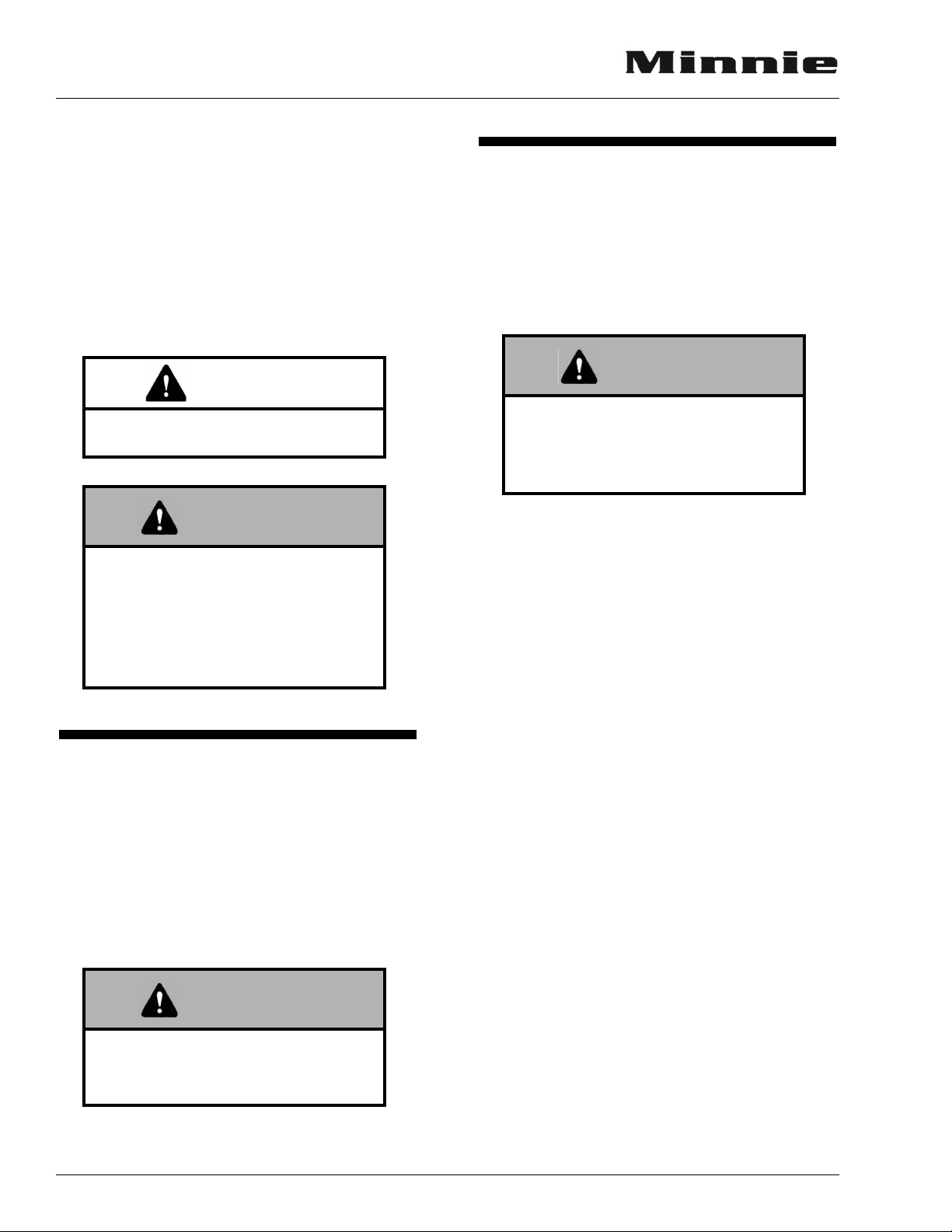
REARVIEW MONITOR SYSTEM Optional
The compact rearview monitor is mounted
into the driver side sun visor.
The push button POWER switch has two
modes - On and Standby.
The Standby position switches the display to
an inactive ‘sleep’ mode that will ‘wake up’
whenever the transmission is shifted into Reverse.
The ON position makes the display visible
when the ignition key is on, whether parked or
traveling down the road, for you to monitor your
tow vehicle or rear traffic.
The screen brightness is adjusted using the
two buttons ‘+’ brighter and ‘-’dimmer.
5-1
5 - DASH / AUTO
SECTION 5
DASH / AUTO
If your motor home is equipped with this
optional system, refer to the Owner InfoCase for
further instructions provided by manufacturer.
TEMP CONTROL - Blue = Cold / Red = Warm
Mode Selector Positions:
Max A/C - Cab air is recirculated (and re-cooled)
through air conditioner.
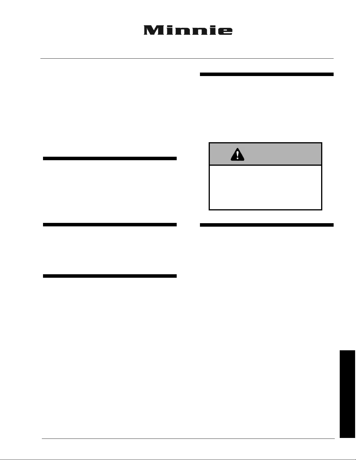
COMFORT CONTROLS
Controls for the air conditioner, heater, defroster and vent are all combined into one control
panel. Refer to the following instructions for use
of individual controls.
Temp
Control
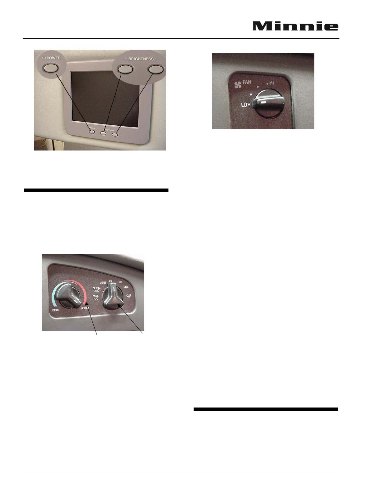
FAN SWITCH - Smallest dot is lowest air
movement; Largest dot is maximum air movement. Fan will run at set speed when mode knob
is in any position except Off. When mode knob is
set to Off, the fan will not run.
Mode
Control
Norm A/C - Directs outside air through air conditioner cooling fins to reduce cab temperature.
NOTE: The dash air conditioner is not designed
to cool the entire interior of the coach,
but is intended to cool the cab area only.
Vent - Directs outside air through dash vents. Incoming air temperature can be adjusted using
temp control knob, although cooling is limited to
a few degrees above ambient outside air temperature.
Floor - Directs most air to floor vents and small
amount to windshield defrost vents.
Mix - Splits air between floor and windshield defrost vents.
Def - Directs most air to windshield defrost vents
and small amount to floor vents.
Off - When no heating, cooling or ventilation are
required; closes all air dampers and turns fan off.
5-2
BATTERY BOOST SWITCH
This switch can be used to provide emergency
starting power from the motor home auxiliary
battery if the automotive battery is dead.
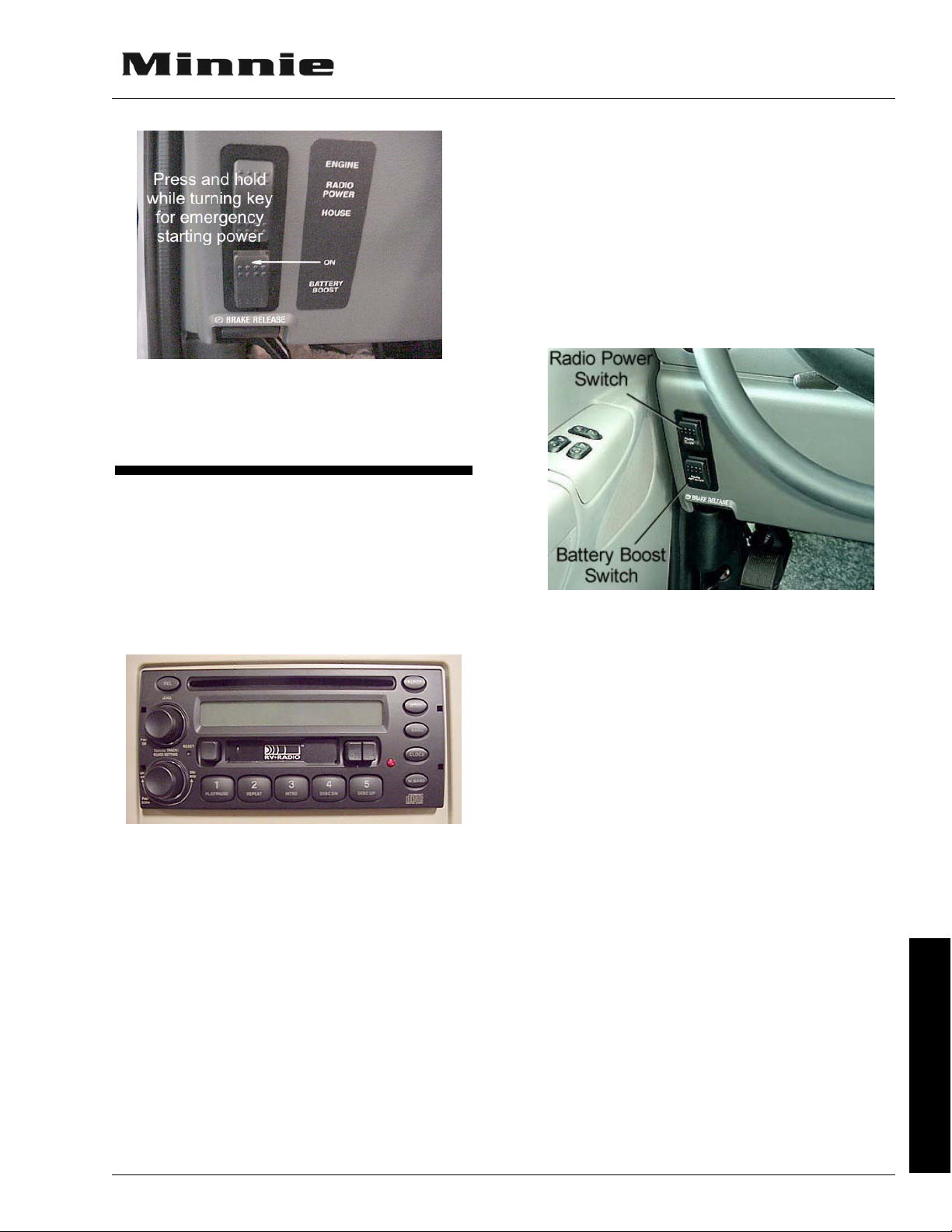
If engine battery is dead, press and hold while
turning ignition key for emergency starting
power.
SECTION 5
DASH / AUTO
An additional hand-held remote allows these
same conveniences for the passenger. The handheld radio remote is in your owner InfoCase.
Radio Power Switch
The radio power switch lets you connect the
dash radio to the coach batteries with the ignition
switch turned off for listening while parked. This
prevents accidental draining of the chassis (starting) battery with prolonged use of the radio.
IN-DASH RV RADIO
TM
The RV RadioTM in your coach can receive
AM/FM stereo and Weather band stations. It also
has both cassette and compact disc (CD) players
for your listening enjoyment through quality
high-output speakers located in several areas of
the coach.
TM
Please refer to the RV Radio
manufacturer’s operating guide in your Owner InfoCase for
detailed instructions on programming preset station buttons and using this full-featured radio/audio system.
Radio Remote Controls
A steering wheel mounted remote control for
the RV Radio lets you change radio stations or
CD selections without taking your eyes off the
road or hands off the wheel. See the RV Radio
owners guide in your Owner InfoCase for remote
control instructions.
5 - DASH / AUTO
5-3

SECTION 6 APPLIANCES & EQUIPMENT
NOTE: Some items described in this section may
be optional and, therefore, may not be in
your vehicle.
The appliances installed in your motor home
are manufactured by reputable RV appliance
makers and have been tested by independent laboratories to meet all applicable standards and
codes set for RV appliances. These appliances
are covered by your New Vehicle Limited Warranty. (Certain items may be covered by individual manufacturer’s warranty.) See your New
Vehicle Limited Warranty for details.
REFRIGERATOR
The refrigerator in your coach can be operated
from either of two power sources available to the
motor home:
− 110-Volt AC electric
− LP gas
The refrigerator is an absorption type which
uses an ammonia-water solution for cooling. Basically, ammonia vapor is distilled from the solution by heat, produced from either LP gas or
electricity, and then carried to the finned condenser where it liquefies. The liquid then flows to
an evaporator where it creates cold temperatures
through evaporation.
EQUIPMENT
6 - APPLIANCES &
Normal vehicle leveling to provide comfort
for the occupants is satisfactory for refrigerator
operation. This will be well within the operation
limits of 3° off-level side-to-side and 6°off-level
front-to-back.
Operating Instructions
Models with Electronic Auto Mode
Control
CAUTION
To prevent permanent damage to the
refrigerator cooling unit, turn the
refrigerator off if the vehicle will be
parked on an incline of over 3° sideto-side or 6° front-to-rear (such as
steep driveways or parking lots, etc.)
for more than one hour.
Leveling
Before operating the refrigerator when the
motor home is stationary, place a small level on
the freezer plate and make certain the unit is
level.
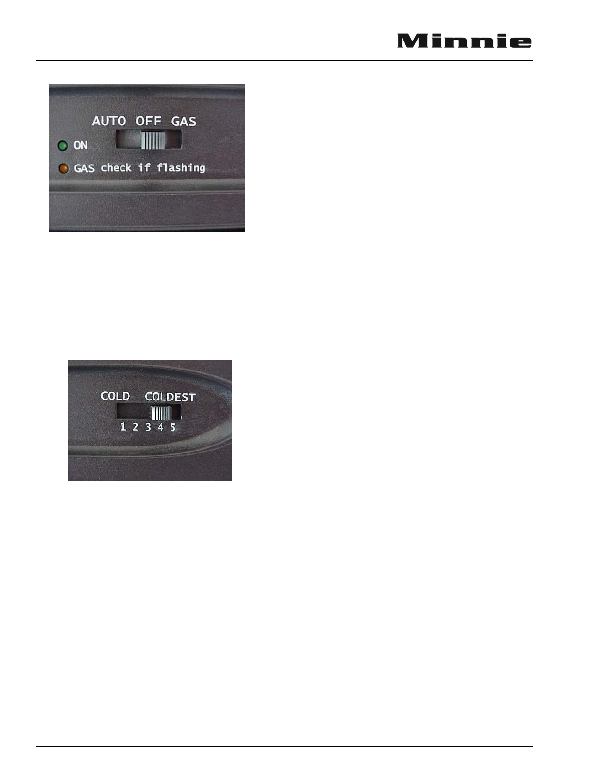
Start-Up Instructions - Gas Mode
The control panel is located between the
freezer compartment and fresh food compartment. It contains mode and temperature switches
and LED indicators. The On and Gas indicators
illuminate to indicate the refrigerator’s operating
mode.
6-1
SECTION 6
APPLIANCES & EQUIPMENT
The above switch turns the refrigerator On or
Off. If the switch is slid to AUTO, it will turn the
refrigerator On and run in automatic mode.
The temperature selector switch controls the
refrigerator and freezer temperature during both
gas and electric operation. Slide the switch to
select the desired temperature setting.
When set to AUTO mode, the refrigerator
will automatically use 110-volt power if the
shoreline is plugged in or generator running. If
110-volt power is not available, the refrigerator
will automatically switch to run on LP gas.
NOTE: The power cord must be plugged into the
generator receptacle for generator operation.
“Diagnostic” section of the “Refrigerator Operator’s Guide” in your Owner InfoCase.
Auto and Manual Modes - Gas
Operation Only
If the gas does not ignite within 30 seconds,
which may occur on initial start-up, the refrigerator’s gas valve will automatically close and the
operating controls will select an alternate power
source (AUTO Mode) or revert to a stand-by
mode in which the GAS indicator flashes. The
indicator continues to flash until the refrigerator
is turned OFF and then ON. If the gas does not
ignite after several attempts, check the input gas
supply, or consult with your dealer or an authorized service center.
Backup Operating System (“BOS”)
Your refrigerator features a Backup Operating System which keeps the refrigerator cool in
the event of a failure of the refrigerator’s operating controls. If a failure occurs, the TEMP SET
LED flashes and refrigerator switches to the
BOS mode. This mode provides refrigeration
until the refrigerator is serviced. The fresh food
and freezer compartment temperatures should be
monitored to prevent over-freezing or thawing of
refrigerator contents when operating in the BOS
mode. If the refrigerator temperature is too cold,
adjust the thermostat to the left in single LED
increments. If the refrigerator temperature is too
warm, adjust the thermostat to the right in single
LED increments. Let the refrigerator operate at
the new setting for one hour before rechecking
the freezer and fresh food compartment temperatures. (Frequent door opening prevents the temperatures from stabilizing.) Although the
refrigerator can operate in this mode, have
refrigerator serviced to restore manual operation
as soon as practical.
If an operating mode is not functional, its
corresponding indicator will flash and the refrigerator will attempt to operate in a lower power
priority source. If a lower power priority source
is not available, the indicator will continue to
flash, and the refrigerator will cease operation
until the energy source is corrected. Refer to the
6-2
Operating Tips
• The refrigerator should already be cold before placing items in it.
• Food and beverages should also be cold before placing in RV refrigerator. Never put
warm or hot items in a cold refrigerator.
• Do not pack the refrigerator too full. The refrigerator needs room for cold air to circulate.
SECTION 6
APPLIANCES & EQUIPMENT
• Use smaller containers for each item. (e.g. a
half gallon container of milk instead of a halffull gallon jug)
• Always put foods, especially liquids, in tightly sealed containers.
• Use crumpled paper between loose items to
reduce rattling or “clinking” noises.
Further Information
For further information and operating cautions, see the refrigerator operating instructions
included either inside the refrigerator or in your
Owner InfoCase.
REFRIGERATOR COMPARTMENT
(Exterior)
The exterior refrigerator compartment allows
access to the rear of the refrigerator for inspection, maintenance and service.
To Close:
1. Replace the door into the opening.
2. Push the latch knobs in while turning to the
horizontal position as shown.
RANGE AND OVEN
The range and oven in your motor home are
operated on LP gas and will provide nearly all of
the functions that the range in your home does.
The range has a “Pilot Off” position on the oven
control which allows the oven pilot to be turned
off when traveling or refilling the LP tank.
The following warning label has been located
in the cooking area to remind you to provide an
adequate supply of fresh air for combustion.
EQUIPMENT
6 - APPLIANCES &
To O pe n:
1. Use a screwdriver or coin to turn the latch
knobs to the vertical position as shown.
2. Remove the door from the opening.
Refrigerator Access Door Latches
WARNING
IT IS NOT SAFE TO USE
COOKING APPLIANCES
FOR COMFORT HEATING
Cooking appliances need fresh air for safe
operation. Before operation
1. Open overhead vent or turn on exhaust fan.
2. Open window
FAILURE TO COMPLY COULD RESULT IN
DEATH OR SERIOUS INJURY.
Unlike large homes, the oxygen supply inside
a recreational vehicle is limited due to its size. To
avoid danger of asphyxiation, provide proper
ventilation when using the gas rangetop or gas
oven. It is especially important not to use the gas
oven and range top for comfort heating. Danger
of asphyxiation is greater when these appliances
are used for long periods of time.
6-3
 Loading...