

Winnebago Journey 34B (2001), Journey 36L (2001), Journey 36G (2001) Owner's Manual

TO THE OWNER
Congratulations! We welcome you to the exciting world of motor home travel and camping. You will
find it convenient and enjoyable to have all the comforts of home and still enjoy the great outdoors wherever you choose to go.
Your Winnebago Journey motor home has been carefully designed, engineered and manufactured to
provide dependability as well as safety. Before sliding into the driver’s seat, take a few minutes to become
familiar with operations and features. This manual was prepared to aid you in the proper care and operation
of the vehicle and equipment. We urge you to read it completely. In addition, spend some time with the
dealer when you take delivery, you will want to learn all you can about your new motor home.
Your new Journey motor home is covered by a factory warranty against defects in material and workmanship. This warranty should be validated at once and returned to the factory by your dealer.
Read and understand all instructions and precautions in this manual before operating your new motor
home. Throughout this manual, certain items are labeled NOTE, CAUTION and WARNING. These terms
alert you to precautions that can involve risk to your vehicle or to your personal safety. Read and follow
them carefully.
NOTE: Indicates a special point of information.
CAUTION
Indicates that a failure to observe can
cause damage to vehicle or equipment
.
WARNING
This symbol is used to alert you to
precautions that involve your personal safety as well as vehicle damage. Read and follow them carefully.
132000-09-000March 2000
OWNER’S NAME
STREET ADDRESS
CITY AND STATE (OR PROVINCE IN CANADA)
MOTOR HOME SERIAL NUMBER
VEHICLE CHASSIS IDENTIFICATION NO. (VIN)
DATE OF DELIVERY TO FIRST RETAIL PURCHASER
VEHICLE MILEAGE AT TIME OF DELIVERY
SELLING DEALER NAME AND ADDRESS
TANK CAPACITIES
Diesel Fuel Tank ...................................................................................90 gals. diesel
LP Gas Tank - All Models...........................................................31 gal. (39 gal. w.c.)
Fresh Water Tank.............................................................................................86 gal.
Water Heater - Standard..................................................................................... 6 gal.
Optional .................................................................................. 10 gal.
Black Water Holding Tank
Model 34B & 36L (Toilet)..................................................................................48 gal.
Model 36G (Toilet) ............................................................................................52 gal.
Grey Water Holding Tank
Model 34B & 36L (Galley, Shower & Lavatory)...............................................52 gal.
Model 36G (Galley, Shower & Lavatory) ..........................................................48 gal.
*LP Gas tank capacity shown is the usable “full” LP gas capacity, which is 80% of the tank
manufacturer’s listed water capacity (w.c. shown in parenthesis). An LP tank must have at least 20% of
tank volume free to allow for expansion and proper vaporization of the liquid fuel. The tank is also
equipped with mandatory safety shut-off equipment that prevents filling above this level.

TABLE OF CONTENTS
INTRODUCTION
About This Manual............................... 0-1
Freightliner Chassis Guide.................... 0-1
Diesel Engine Manual........................... 0-1
Owner’s InfoCase ................................. 0-2
Options and Equipment ........................ 0-2
Before Driving...................................... 0-2
Service Assistance ................................0-2
Warranty................................................ 0-2
Drinking and Driving............................ 0-2
Reporting Safety Defects...................... 0-3
Vehicle Certification Label ................... 0-4
Exterior Feature Identification.............. 0-5
SECTION 1: SAFETY PRECAUTIONS
General Warnings..................................1-1
Driving.................................................. 1-1
Fuel & LP Gas ......................................1-2
LP Gas Leaks ....................................... 1-3
LP Gas Alarm .......................................1-3
Electrical............................................... 1-4
Loading................................................. 1-4
Maintenance..........................................1-4
Formaldehyde Warning......................... 1-5
Carbon Monoxide Warning...................1-5
Carbon Monoxide Alarm......................1-5
Emergency Exit Window......................1-6
Fire Extinguisher................................... 1-7
Smoke Alarm........................................ 1-7
SECTION 2: DRIVING YOUR MOTOR
HOME
Before Entering Vehicle........................ 2-1
Before Driving Vehicle......................... 2-1
“Key One” Lock System....................... 2-2
Fuel Selection ....................................... 2-2
Fuel Fill................................................. 2-2
Fuel Tank Capacity............................... 2-2
Starting and Stopping Engine ............... 2-2
Engine Block Heater............................. 2-3
Parking Brake ....................................... 2-3
Exhaust Braking System....................... 2-4
Hazard Warning Lights......................... 2-4
Door Locks and Handles....................... 2-4
Entrance Step........................................ 2-5
Entrance Stepwell Cover....................... 2-6
Power Mirrors.......................................2-7
Rearview Monitor System .................... 2-8
Seats...................................................... 2-9
Seat Belts ............................................ 2-10
Child Restraints................................... 2-11
Instrument Panel................................. 2-13
Multi-Function Signal Lever ..............2-14
Steering Tilt/Telescope ....................... 2-14
Cruise Control.....................................2-14
Comfort Controls................................ 2-15
Heating.............................................2-15
Defrosting ........................................ 2-15
Ventilation........................................ 2-15
Air Conditioning.............................. 2-16
Antenna Check Light.......................... 2-16
Sound System .....................................2-16
Compact Disc (CD) Changer.............. 2-17
Auxiliary Start Switch.........................2-17
Auxiliary Battery Switch.................... 2-17
CB Radio Wiring................................ 2-17
Coach Leveling System...................... 2-18
Slideout Room Extension ................... 2-19
Front Slideout Emergency Crank-in... 2-21
SECTION 3: IN CASE OF DRIVING
EMERGENCY
Hazard Flashers..................................... 3-1
If You Get A Flat Tire........................... 3-1
Recovery Towing.................................. 3-1
Jump Starting........................................ 3-2
Connecting a Battery Charger............... 3-3
Engine Overheat ................................... 3-3
SECTION 4: TRAVELING WITH YOUR
MOTOR HOME
Loading the Vehicle .............................. 4-1
Front Axle Tire Alignment................... 4-1
Weighing Your Loaded Vehicle............ 4-1
Maximum Occupancy...........................4-2
Roof Loading........................................ 4-2
Car or Trailer Towing ........................... 4-2
Pre-Travel Checklist ............................. 4-3
Travel Tips............................................ 4-3
Severe Weather Information .................4-4
Nighttime Driving.................................4-5
Mountain Driving ................................. 4-5
Campsite Selection ............................... 4-6
Leveling................................................ 4-6

TABLE OF CONTENTS
Effects of Prolonged Occupancy ..........4-6
Humidity and Condensation .................4-6
SECTION 5: LP GAS SYSTEM
LP Gas Supply ..................................... 5-1
Safe Use of LP Gas System.................. 5-1
How LP Gas Works .............................. 5-1
Selecting Fuel Types............................. 5-2
LP Tank System....................................5-2
Refilling Tank ....................................... 5-2
Air in the LP Gas Tank ......................... 5-3
Traveling with LP Gas.......................... 5-3
Regulator............................................... 5-4
LP Gas Leaks........................................5-4
Winter Use of LP Gas........................... 5-5
SECTION 6: ELECTRICAL SYSTEMS
110-Volt AC System............................. 6-1
External Power Cord (Shoreline)..........6-1
Connecting the Shoreline......................6-2
PowerLine Energy Management
System................................................ 6-3
Power Converter System ......................6-3
110-Volt Circuit Breakers..................... 6-4
Charging Section................................... 6-4
Thermal Overload Protector .................6-4
110-Volt Receptacles (Outlets)............. 6-5
Ground Fault Circuit Interrupter
(GFCI)................................................ 6-5
Auxiliary 110-Volt Generator
Operating Instructions.................6-6, 6-7
12-Volt DC System ............................... 6-8
12-Volt Fuses and Circuit Breakers ......6-8
Solar Charger Panel .............................. 6-8
Battery Information............................... 6-9
Chassis (Starting) Battery..................... 6-9
House Batteries.....................................6-9
Battery Storage and Maintenance.........6-9
Trailer Wiring Connector....................6-10
SECTION 7: PLUMBING SYSTEMS
Fresh Water System .............................. 7-1
Filling Water Tank ................................7-1
Fresh Water Tank Capacity................... 7-1
Water Pump........................................... 7-2
Water Pump Switch...............................7-2
Accumulator Tank................................. 7-3
Disinfecting Water Tank ....................... 7-3
External (City Water) Connector ..........7-4
Water Purifier System........................... 7-4
Exterior Shower.................................... 7-5
Waste Water System .............................7-5
Dumping Holding Tanks....................... 7-6
Flushing Black Water Holding Tank..... 7-6
Using On-Site Sewer Hook-Ups...........7-6
Utility Light .......................................... 7-7
Water Drain Valves........................7-7, 7-8
Holding Tank Capacities....................... 7-9
SECTION 8: APPLIANCES AND
INTERIOR FEATURES
Refrigerators & Ice Makers ..........8-1 - 8-5
LP Gas Cook Top.................................. 8-5
Microwave Convection Oven............... 8-6
Range Hood ..........................................8-6
Monitor Panel .......................................8-7
Tank Levels, Checking.......................... 8-7
Water Pump Switch ..............................8-8
Battery Voltage Meter........................... 8-8
Washer-Dryer........................................ 8-9
Water Heater ......................................... 8-9
Water Heater By-Pass Valve............... 8-12
LP Gas Furnace................................... 8-13
Thermostat.......................................... 8-13
Central Air Conditioner...................... 8-14
Air Conditioner Filter ......................... 8-14
TV Antenna......................................... 8-15
TV Signal Amplifier........................... 8-16
Video Selector System........................ 8-16
Digital Satellite System ......................8-16
Exterior Entertainment Center ........... 8-17
Cable TV Hook-Up ............................ 8-17
Dinette Table & Chairs ....................... 8-18
Sleeping Facilities
Couch-Bed Conversion.................... 8-20
Fresh Water Toilet............................... 8-20
Power Roof Vents ..............................8-21
Slider Windows................................... 8-21
SECTION 9: CARE AND MAINTENANCE
Roof ...................................................... 9-1
Underbody ............................................ 9-1
Exterior .................................................9-1
Stripes and Decals, care of.................... 9-1
Compartment Doors.............................. 9-2
Interior Maintenance
Upholstery, Carpet and Draperies...... 9-2
Cabinets ............................................. 9-3
Tables and Countertops...................... 9-3
Vinyl Wallboard................................. 9-3
Stainless Steel Sink............................ 9-3

Bathroom ...........................................9-4
Doors and Windows.............................. 9-4
Vehicle Maintenance
Chassis Service and Maintenance...... 9-4
Engine Access....................................9-4
Diesel Fuel/Water Separator ............. 9-5
Engine Cooling System .....................9-5
Tires ................................................... 9-6
Suspension Alignment and Tire
Balance............................................ 9-6
Windshield Washers and Wipers........9-6
Lights ................................................. 9-6
Automotive 12-Volt Circuit Breakers 9-7
SECTION 10: STORING YOUR MOTOR
HOME
Preparing Vehicle for Storage............. 10-1
Cold Weather Storage
(Winterizing)........................10-1 to 10-4
RV Antifreeze Winterization
Systems.......................................... 10-4
Removal from Storage........................ 10-5
TABLE OF CONTENTS

INTRODUCTION
Congratulations on the purchase of your new
Winnebago Journey motor home, which has been
carefully designed, engineered and quality built
by Winnebago Industries, Inc.
ABOUT THIS MANUAL
Please read this operator’s manual complete-
ly to understand how everything in your coach
works before taking it on its “maiden voyage.”
This manual is a guide to safe operation of the
features, equipment and controls in this coach.
Some equipment, such as the vehicle chassis and
certain electronic systems or appliances, have
their own comprehensive, manufacturer supplied
manuals or information sheets which describe
operation of these products in great detail. This
manual will refer you to the manufacturer’s information included in your Owner INFOCASE
whenever necessary.
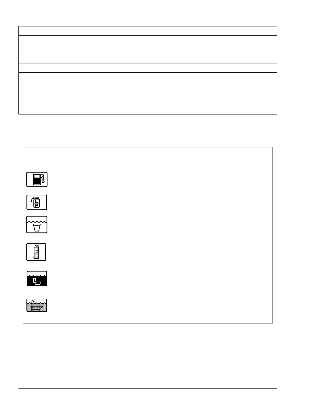
SUBJECT ICONS - To make it easy for you
to find information you’re looking for, we have
placed convenient, pictorial symbols called
“icons” beside many of the subject headings in
this manual. The icons correspond to the subject
matter of the section. These icons were designed
similar to the familiar international symbols
which identify public facilities such as restrooms
and handicap access. There are several examples
of icons on this page.
PAGE ICONS - The icons at the upper cor-
ners of each page correspond to the primary content of each main section of the manual, such as
LP Gas, Electrical, Plumbing, etc. This means
you can flip through the manual either forward or
backward and know exactly which main section
you are looking for just by watching the icons at
the top of the page. This means less paging back
and forth.
We also urge you to read the complete
Chassis Operating Guide provided by the
chassis maker and all other operating information provided by our equipment suppliers
and manufacturers. This is contained in your
Owner I
NFOCASE.
This manual should be kept in the vehicle at
all times for personal reference. The operator’s
manual, I
are to be considered permanent components of
this vehicle. They should remain in the vehicle
when sold to provide the next owner with important safety, operating and maintenance information.
NOTE: The descriptions, illustrations, and spec-
NFOCASE and chassis operating guide
ifications in this manual were correct at
the time of printing. We reserve the right
to change specifications or design without notice, and without incurring obligation to install the same on products
previously manufactured.
FREIGHTLINER CHASSIS
OPERATING GUIDE
Throughout this manual, frequent reference
is made to the vehicle chassis operating guide.
The chassis guide is the operator’s manual provided by Freightliner, the manufacturer of the
chassis on which this motor home is built. Consult the chassis guide for operating safety and
maintenance instructions pertaining to the chassis section of the motor home.
DIESEL ENGINE MANUAL
Consult your Caterpillar or Cummins Diesel
Engine Operation and Maintenance Manual for
information on all engine related topics such as
engine maintenance, fluid level checks, capacities, and service parts, etc.
0-1
INTRODUCTION
OWNER’S INFOCASE
SERVICE AND
ASSISTANCE
Your InfoCase contains information supplied
by manufacturers of individual appliances and
equipment installed in your motor home.
Consult this information regarding the operation and care of appliances, accessories and special equipment.
OPTIONS AND EQUIPMENT
Some equipment described in this manual
may not apply to your coach.
BEFORE DRIVING
Before sitting in the driver’s seat, always
check around your vehicle to be sure you have
proper clearance for maneuvering. If necessary,
have a passenger help guide you out of a difficult
parking space.
Although your coach features automotive
conveniences like power steering and power
brakes, driving a motor home is different from
driving a car. A motor home is larger and heavier
than an automobile, so it requires more stopping
and passing distance, and more parking and maneuvering space than a car does.
Always be aware of the size of your motor
home. The added height of TV antennas or luggage boxes may cause clearance problems
around some tunnels, canopies and hanging
signs. Know the height of your coach so you can
observe posted clearance limits. Also, remember
that some bridges, old ones in particular, may not
support the weight of your motor home. Know
the weight of your unit and observe any posted
weight limits.
Remember: Always use your seat belt and be
sure your passengers do so as well. We also advise making frequent rest stops while traveling to
relieve stress on yourself, your passengers and
your vehicle.
Your Winnebago Industries dealer will be
glad to provide any additional information you
need, as well as answer any questions you might
have about operating the equipment in your
motor home. When it comes to service, remember that your dealer knows your vehicle best and
is interested in your satisfaction. Your dealer will
provide quality maintenance and any other assistance that you may require during your ownership of this vehicle.
If you need warranty repairs while traveling,
however, you may take your motor home to any
Winnebago or Itasca dealership and they will assist you.
WARRANTY
Your new Journey is covered by a factory
warranty against defects in material and workmanship. This warranty should be validated immediately and returned to the factory by your
dealer. For additional information, see your
“New Vehicle Limited Warranty” included with
this vehicle.
DRINKING AND DRIVING
Winnebago Industries supports the recommendations of the Presidential Commission on
Drunk Driving.
• Exercise your good judgment and encourage
others to do the same.
• Know the legal limits and do not exceed
them.
• Also know your personal limits, which may
be lower than the legal limits.
• Should you ever exceed your limits, find al-
ternative transportation; call a cab, ask a
friend to drive you home or call a family
member to come and get you.
0-2

The presence of alcohol in significant levels
in the blood increases the probability that the
driver will be involved in an accident.
REPORTING SAFETY DEFECTS
If you believe that your vehicle has a defect
which could cause a crash or could cause injury
or death, you should immediately inform the National Highway Traffic Safety Administration
(NHTSA) in addition to notifying Winnebago Industries, Inc.
If NHTSA receives similar complaints, it
may open an investigation, and if it finds that a
safety defect exists in a group of vehicles, it may
order a recall and remedy campaign. However,
NHTSA cannot become involved in individual
problems between you, your dealer, or Winnebago Industries.
To contact NHTSA, you may either call the
Auto Safety Hotline toll-free at 1-800-424-9393
(or 366-0123 in Washington, D.C. area) or write
to: NHTSA, U.S. Department of Transportation,
Washington, D.C. 20590. You can also obtain
other information about motor vehicle safety
from the Hotline.
INTRODUCTION
0-3

INTRODUCTION
VEHICLE CERTIFICATION LABEL
This label contains vehicle identification and
other important reference information. The vehicle certification label is located on the sidewall to
the left of the steering wheel, or on the driver’s
door. Never remove or destroy this label.
MANUFACTURED BY
3
GAWR:
FRT______ LB______ KG________________ ________________ ______ PSI______ KPA SINGLE
RR. _______ LB______ KG________________ ________________ ______ PSI______ KPA______
THIS VEHICLE CONFORMS TO ALL APPLICABLE FEDERAL MOTOR VEHICLE SAFETY
STANDARDS IN EFFECT ON THE DATE OF MANUFACTURE SHOWN ABOVE.
SERIAL NO. _________________________ VIN______________________________
TYPE ____________________ MODEL ____________________ COLOR__________
5
10
12
SUITABLE TIRE AND RIM CHOICE COLD INFLATION
EXPLANATION OF DATA
1. Chassis manufacturer.
2. Chassis manufacture date.
3. Month and year of manufacture at Win-
nebago Industries.
4. Gross Vehicle Weight Rating: Total permis-
sible weight of the vehicle, including driver,
passengers, total cargo carried (including all
liquids) and equipped with all options.
5. Gross Axle W eight Rating: Total permissible
weight allowed for the front and rear axles
(listed in pounds and kilograms).
6. Suitable Tire Choice: Tires recommended to
meet handling and safety requirements.
When replacing any of the tires on your
vehicle, always replace with a tire that meets
these specifications.
INCOMPLETE VEHICLE MANUFACTURED
BY MOTOR CORP.
MONTH AND YEAR OF MANUFACTURE:________
GVWR_______LB _________KG
TIRE RIM PRESSURE
6
1
4
7
11
13
8
14
9. Intermediate* and Rear Axle Wheel Configuration: Single or Dual.
10. Serial Number: This is the serial number
assigned to the completed vehicle by Winnebago Industries.
11. Vehicle Identification Number (VIN): This
number identifies the chassis on which the
motor home is built.
12. Type: States the NHTSA designated usage
classification for your motor home. MPV
signifies a Multi-purpose Passenger Vehicle.
13. Model: Lists the Winnebago product model
number of your vehicle.
14. Color: Signifies the color code number of the
decor used throughout the vehicle. This
number is necessary for ordering replacement cushions, curtains, carpet, etc.
2
7. Suitable Rim Choice: Wheel rims recommended to meet handling and safety requirements. When replacing any of the rims on
your vehicle, always replace with a rim that
meets these specifications.
8. Cold Inflation Pressure: Inflation pressures
recommended (while Cold) for the tires originally equipped on your vehicle. These pressure levels must be maintained to assure
proper handling, safety and fuel economy.
9
0-4
Vehicle Certification Label
INTRODUCTION
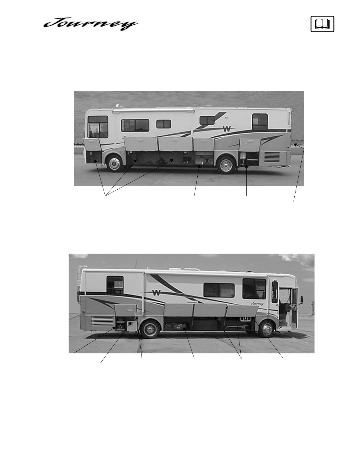
EXTERIOR FEATURE IDENTIFICATION
Composite model shown for illustration purposes only.
Actual locations of features depends on coach model and options.
Batteries
Storage
Compartments
!Water Heater
Service Access
!Furnace Intake/
Exhaust Port
Holding Tank
Dump Valves
LP Gas
Tank
Water Center/
Shoreline
Compartment††
Storage
Compartments**
Engine Fluid
Check Access*
Exterior
Entertainment
Center (Opt.)
NOTE: Some equipment shown may be optional.
*Also contains diesel fuel filter/water separator.
**Also contains optional freezer unit if equipped.
††Also contains Cable TV and Phone hookups and engine block heater plug-in.
!Be Careful! Exhaust outlet surface may become HOT while using furnace or water heater.
0-5

SECTION 1
SAFETY PRECAUTIONS
Read and understand all instructions and precautions in this manual before operating your
new motor home. Throughout this manual, certain items are labeled NOTE, CAUTION and
WARNING. These terms alert you to precautions
that can involve risk to your vehicle or to your
personal safety. Read and follow them carefully.
NOTE: Indicate special points of information.
CAUTION
Indicates that a failure to observe can
cause damage to vehicle or equipment
WARNING
This symbol is used to alert you to
precautions that involve your personal safety as well as vehicle damage. Read and follow them carefully.
Listed below are some safety precautions that
must be adhered to. These precautions as well as
others that involve damage to equipment are also
listed in the appropriate areas in this manual.
• Make sure all passengers have seat belts fastened in a low and snug position so the force
exerted by the belt in a collision will be
spread across the strong hip area. Pregnant
women should wear a lap-shoulder belt
whenever possible, with the lap belt portion
worn low and snug throughout the pregnancy.
• Before driving, secure dinette chairs with retainer strap provided as shown in Section 8.
• Never let passengers stand or kneel on seats
while the vehicle is moving.
• Sleeping facilities are not to be utilized while
vehicle is moving.
• Examine the escape window and be familiar
with its operation, but do not use except in an
emergency.
• Ιnspect the fire extinguisher monthly for
proper charge and operating condition. This
should also be done before beginning a vacation or any extended trip.
GENERAL WARNINGS
• Only seats equipped with seat belts are to be
occupied while the vehicle is moving.
• All seats which can be positioned, such as
swiveling, sliding, reclining, or footrest out,
must be placed in a fully upright and swivellocked position with footrests retracted while
the vehicle is moving. Some swivel lounge
chairs are designed to lock in a forward
facing position, while others lock in an aisle
facing position. Be certain these seats are
secure from swiveling before traveling.
DRIVING
• Do not attempt to adjust the driver’s seat
while the vehicle is moving.
• Do not adjust tilt steering in a moving vehicle.
• Do not operate the cruise control on icy or
extremely wet roads, winding roads, in heavy
traffic, or in any other traffic situation where
a constant speed cannot be maintained.
• Use care when accelerating or decelerating
on a slippery surface. Abrupt speed changes
can cause skidding and loss of control.
1-1
SECTION 1
WARNING
NOT SAFE TO USE COOKING
APPLIANCES FOR COMFORT HEATING
COOKING APPLIANCES NEED FRESH AIR FOR SAFE OPERATION.
BEFORE OPERATION:
1. OPEN OVERHEAD VENT OR TURN ON EXHAUST FAN AND;
2. OPEN WINDOW.
SAFETY PRECAUTIONS
• Driving through water deep enough to wet
the brakes may affect stopping distance or
cause the vehicle to pull to one side. Check
brake operation in a safe area to be sure they
have not been affected. Never operate any
vehicle if a difference in braking efficiency is
noticeable.
• Adverse weather conditions and extremes in
terrain may affect handling and/or performance of your vehicle. Refer to your chassis
manual for related information.
FUEL & LP GAS
• All pilot lights must be extinguished and appliances turned off while refilling the fuel
tank or LP tank.
• Never smoke while refilling vehicle fuel tank
or LP gas tank.
• Avoid inhaling exhaust gases produced by
burned gasoline, diesel fuel or LP gas in
items such as the range, chassis engine, generator engine, refrigerator, furnace and water
heater. They contain carbon monoxide,
which is an odorless, colorless and poisonous
gas.
• Do not bring or store LP gas containers, gasoline or other flammable liquids inside the
vehicle because a fire or explosion may result. LP gas containers are equipped with
safety valves which relieve excessive pressure by discharging gas to the atmosphere.
• Do not alter the LP gas system at any time or
in any way.
• Do not fill LP gas container(s) above 80 percent of capacity. Overfilling the LP gas container can result in uncontrolled gas flow
which can cause fire or explosion. A properly
filled container will contain approximately
80 percent of its volume as liquid LP gas.
1-2
• Never use an open flame to test for LP gas
leaks. Replace all protective covers and caps
on LP system after filling. Make sure valve is
closed and door latched securely.
• Never connect natural gas to the LP gas system.
• When lighting range burners do not turn
burner controls to “On” and allow gas to escape before lighting match.
• Portable fuel-burning equipment, including
wood and charcoal grills and stoves, shall not
be used inside the recreational vehicle. The
use of this equipment inside the recreational
vehicle may cause fires or asphyxiation.
• LP gas regulators must always be installed
with the diaphragm vent facing downward.
Regulators are equipped with a protective
cover. Make sure that the regulator vent faces
downward and that the cover is kept in place
to minimize vent blockage which could result
in excessive gas pressure causing fire or explosion.
• The following warning label is located in the
cooking area to remind you to provide an adequate supply of fresh air for combustion.
IT IS NOT SAFE TO USE COOKING IT IS
APPLIANCES FOR COMFORT HEATING
COOKING APPLIANCES NEED FRESH AIR FOR SAFE OPERATION.
BEFORE OPERATION:
1. OPEN OVERHEAD VENT OR TURN ON EXHAUST FAN AND;
2. OPEN WINDOW.
Unlike large homes, the oxygen supply inside
a recreational vehicle is limited due to its
size. To avoid danger of axphyxiation, provide proper ventilation when using the gas
rangetop or gas oven. It is especially important that the gas oven and range top not be
used for comfort heating. Danger of asphyxiation is greater when these appliances are
used for long periods of time.
SECTION 1
SAFETY PRECAUTIONS
LP GAS LEAKS
The following label is located in the vehicle
near the range area. If you smell gas within the
vehicle, quickly and carefully perform the procedures listed.
IF YOU SMELL GAS
1. Extinguish any open flames, pilot
lights and all smoking materials.
2. Do not touch electrical switches.
3. Shut off the gas supply at the tank
valve(s) or gas supply connection.
4. Open doors and other ventilating
openings.
5. Leave the area until odor clears.
6. Have the gas system checked and
leakage source corrected before
using again.
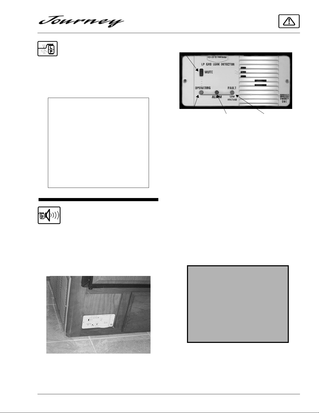
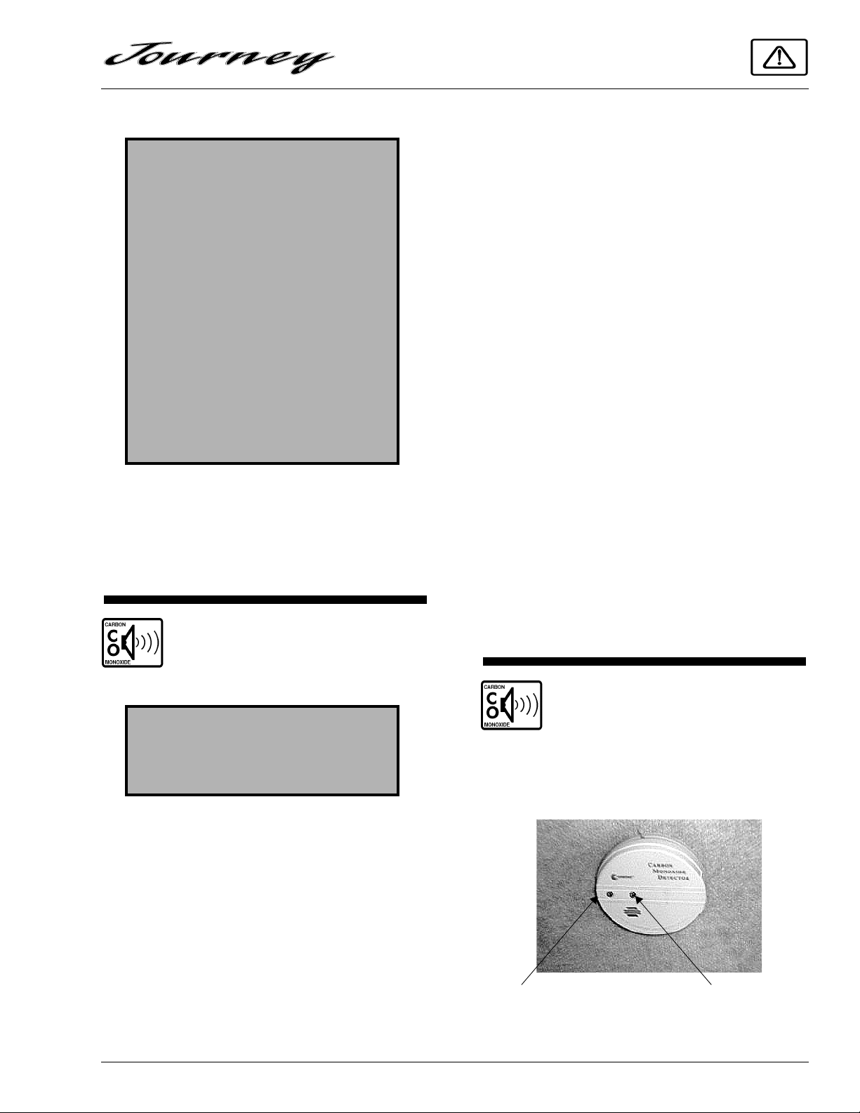
LP GAS ALARM
Your coach is equipped with an LP gas detector which sounds an alarm if an unsafe amount of
LP gas is present inside the coach. Because LP
gas is heavier than air, the detector is located on
a cabinet face near the floor of the coach.
Press to stop alarm
Green
(Active)
If The Alarm Sounds
If the alarm sounds, do not touch any electrical switches. Immediately turn off the main LP
tank valve and all LP appliances, open all windows and roof vents, and leave the coach until
the alarm stops sounding.
If the alarm keeps sounding at regular intervals, a leak may be present. Contact your dealer
or an LP gas service center to have the problem
corrected before using the LP system again.
If the coach batteries become extremely
drained, an amber light on the face of the alarm
will come on and in some cases the LP alarm may
begin to sound on its own. This condition typically occurs only during storage situations when
battery charge is not being restored by the inverter charger or solar charger.
Red
(Alarm)
Amber
(Low Batt.)
A green light on the face of the alarm shows
when the unit is active. The red button is used to
reset the alarm.
WARNING
Never use an open flame to test for
gas leaks. When testing for gas line
leaks with a soapy water solution, DO
NOT use a detergent containing
ammonia or chlorine. These substances may generate a chemical
reaction causing corrosion to gas
lines, resulting in dangerous leak conditions.
Power Connection
The gas alarm is powered by the coach batteries. If the battery cable is disconnected from the
batteries, auxiliary battery switch is shut off, or
the circuit breaker is tripped, the alarm will not
1-3
SECTION 1
SAFETY PRECAUTIONS
work. The LP gas alarm breaker is located on the
coach breaker fuse panel shown on page 6-8.
Because the LP gas alarm is connected directly to the auxiliary battery, it is always drawing a
small amount of current. Even though this current
draw is slight, it could drain the coach battery
during storage periods of 30 days or longer. We
recommend turning the auxiliary battery switch
off or disconnecting the battery cables from the
auxiliary battery during extended storage periods
to avoid discharge.
Further Information
See the manufacturer’s information entitled
“Your LP Gas Detector” in the Owners InfoCase
for further instructions on nuisance alarms and
care and testing of the LP gas detector.
LOADING
• Store or secure all loose items inside the
motor home before traveling. Possible overlooked items such as canned goods or small
appliances on the countertop, cooking pans
on the range, or free-standing furniture items
can become dangerous projectiles during a
sudden stop.
• Be aware of GVWR, GAWR and individual
load limit on each tire or set of duals. (See
“Loading the Vehicle” in Section 4.)
• Never load the motor home in excess of the
gross vehicle weight rating or the gross axle
weight rating for either axle.
ELECTRICAL
• Careless handling of electrical components
can be fatal. Never touch or use electrical
components or appliances while feet are bare,
while hands are wet, or while standing in
water or on wet ground.
• Improper grounding of the vehicle can cause
personal injury. Do not plug the utility power
cord into an outlet which is not grounded and
do not adapt the plug to connect to a receptacle for which it is not designed.
• Do not attach an extension cord to the utility
power cord.
• Be sure that all electrical appliances to be
used contain 3-prong plugs for proper
grounding.
• Avoid overloading electrical circuits. Replace fuses or circuit breakers with those of
the same size and amperage rating only.
Never use a higher rated fuse or breaker.
MAINTENANCE
• Do not remove the radiator cap while engine
and radiator are still hot. Always check coolant level visually at the see-through coolant
reservoir.
• Never get beneath a vehicle that is held up by
a jack.
• Do not mix different construction types of
tires on the vehicle such as radial, bias or belted tires, as vehicle handling may be affected.
Replace tires with exact size, type and load
range.
• Do not attempt to start the vehicle by hot wiring.
• Use caution when handling or working near
electrical storage batteries. Always remove
jewelry and wear protective clothing and eye
covering. Avoid creating sparks.
1-4
SECTION 1
SAFETY PRECAUTIONS
FORMALDEHYDE INFORMATION
WARNING
Some components in this vehicle contain formaldehyde based adhesives
which may release formaldehyde
fumes into the air for an unknown
period of time until total dissipation
occurs. Individuals who are allergic
to formaldehyde gas fumes may
experience irritation to eyes, ears,
nose and throat. Reaction in infants
may be more severe. Although long
range effects are not well understood,
testing to date has not revealed any
serious health effects in humans at the
level of emission from these
products.
IMPORTANT
To aid in dissipation, ventilate the vehicle by
opening all windows and circulating the air with
a fan.
CARBON MONOXIDE
WARNING
• Each time the vehicle is raised for an oil
change.
• Whenever a change in the sound of the exhaust system is noticed.
• Whenever the exhaust system, underbody or
rear of the vehicle is damaged.
To allow proper operation of the vehicle’s
ventilation system, keep front ventilation inlet
grill clear of snow, leaves or other obstructions at
all times. DO NOT OCCUPY A PARKED VEHICLE WITH ENGINE RUNNING FOR AN
EXTENDED PERIOD.
Do not run engine in confined areas, such as a
garage, except to move vehicle in or out of area.
When vehicle is stopped in an UNCONFINED
area with the engine running for any more than a
short period, adjust heating or cooling system to
force outside air into the vehicle as follows:
1. Set fan to medium or high speed and vent
control to air.
2. On vehicles equipped with air conditioning,
set fan to medium or high speed and set control to obtain maximum vent air.
Rear windows should be closed while driving
to avoid drawing dangerous exhaust gases into
the vehicle.
WARNING
Avoid inhaling exhaust gases, as they
contain carbon monoxide, which is a
colorless, odorless and poisonous gas.
If your suspect that exhaust fumes are entering
the passenger compartment, have the cause determined and corrected as soon as possible. If you
must drive under these conditions, drive only
with ALL WINDOWS FULLY OPENED.
The best protection against carbon monoxide
entry into the vehicle body is a properly maintained engine exhaust and ventilation system. It is
recommended that the exhaust system and body
be inspected by a qualified motor home service
center.
CARBON MONOXIDE
ALARM
Your coach is equipped with a carbon monoxide (CO) alarm, located on the ceiling in the bedroom area.
Red Light
(Press to Test Alarm)
Yellow Light
(Warning)
1-5
SECTION 1
SAFETY PRECAUTIONS
The CO alarm is powered by a 9-volt battery
and contains a sensor that is designed to detect
toxic carbon monoxide gas fumes resulting from
incomplete combustion of fuel. It will detect CO
gas from any combustion source such as the furnace, gas range/oven, water heater, refrigerator,
chassis engine, and electric generator engine.
• Patented biomimetic sensor mimics the
human response to Carbon Monoxide.
• Test/Reset provides for one time alarm
silence and multiple warning silence. Also
tests alarm circuitry, microprocessor, battery
and horn.
• Red light flashes once every thirty seconds in
normal operation.
• Continuous yellow light with a beep every
three seconds indicates an unhealthy CO
level.
• Continuous red light and pulsating alarm sig-
nal a dangerous CO condition.
• Battery operation provides protection 100%
of the time. Low battery signal alerts consumer of need to replace battery.
• 85 decibel alarm assures waking during
sleeping hours.
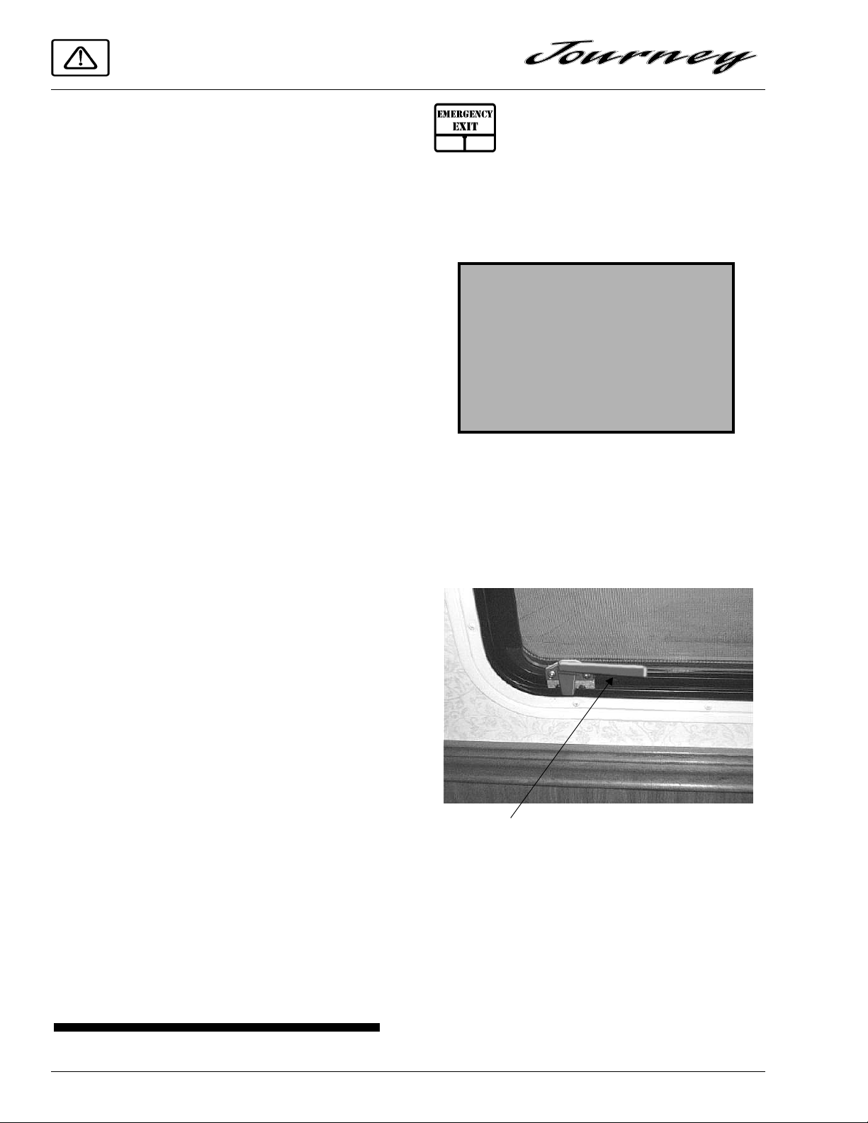
EMERGENCY EXITS
Emergency Exit Windows
Your motor home is equipped with an emergency exit window on the left (driver’s) side of
the bedroom which functions as an escape exit in
an emergency situation.
WARNING
Use emergency window for emergency exit only . Do not test for proper
operation.
Use care when exiting emergency
window, as broken glass may be
present in the exit area.
The side mounted escape window is secured
by two safety latches and can be opened by first
releasing these two latches and then pushing outward on the lower part of the window. Identify
which type of emergency exit window is in your
vehicle.
Monthly Testing
Press the TEST button on the face of the alarm
periodically (at least monthly) to check the function of the alarm and condition of the battery. If
the alarm begins to beep every few seconds, the
battery may be weak and need replacement.
(Press the TEST button to be sure before replacing the battery. If the alarm sounds, the battery
may still be okay. If the alarm still beeps every
few seconds, check the smoke detector also. The
“low battery” warning beep is similar on many
alarm devices, so the origin of this electronic
sound can be deceiving.)
Further Information
Please read the information provided by the
manufacturer, which is included in your Owner’s
InfoCase. It includes information on precautions,
operational testing, and battery/sensor replacement.
Lift Both Handles Up
Push Out on Bottom of Window
Instructions for removal are also located on a
label on the glass for quick reference and for passengers who may not be familiar with the exit.
Never remove or destroy this label.
Using Slider Windows as Emergency Exits
Slider windows along the side of the motor
home can also be used as emergency exits,
1-6
should the need arise. To use the windows as
exits, slide the window open, then slide the
screen open.
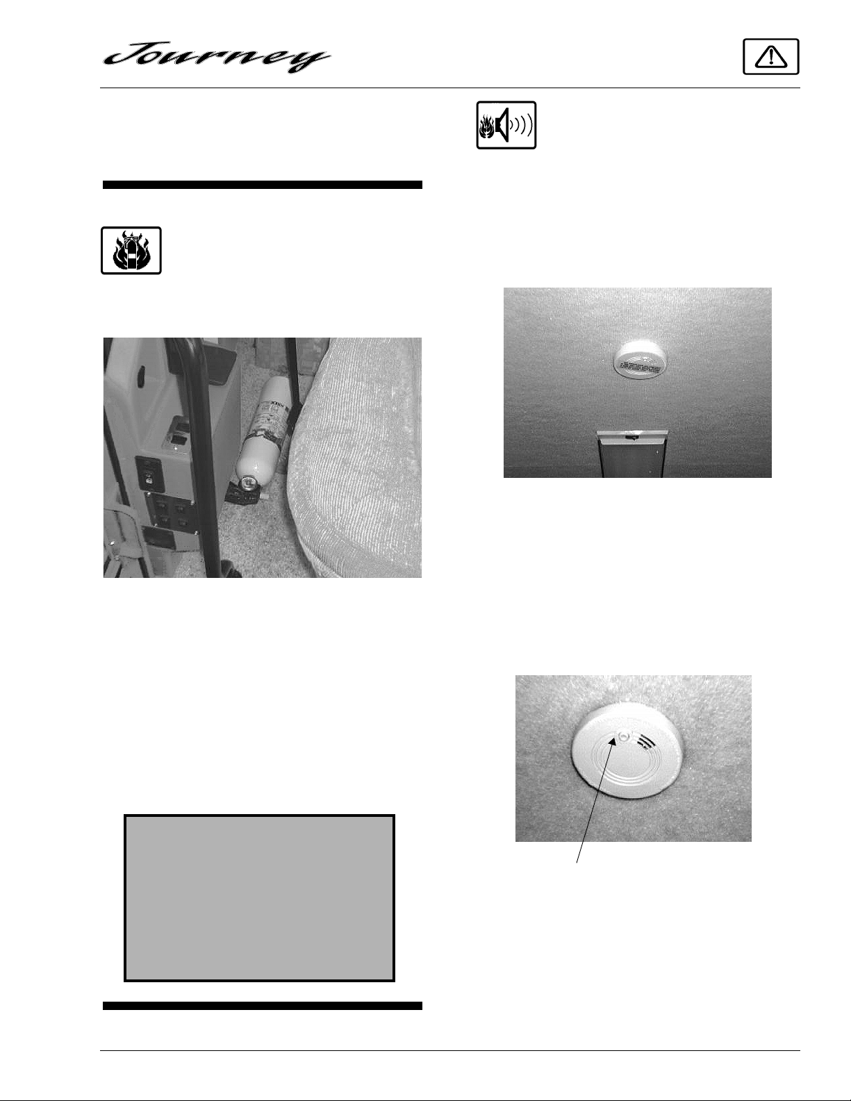
SAFETY DEVICES
FIRE EXTINGUISHER
A dry chemical fire extinguisher is located
near the floor by the passenger side front door.
SECTION 1
SAFETY PRECAUTIONS
SMOKE ALARM
Your motor home is equipped with a smoke
alarm located on the ceiling in the galley and
lounge area. This alarm meets U.L. Standard 217
and NFPA Standard 74 for operation of smoke
detection devices.
We recommend that you become thoroughly
familiar with the operating instructions displayed
on the side of the fire extinguisher or in the information supplied in your Owner’s InfoCase.
We also recommend that you inspect the fire
extinguisher for proper charge at least once a
month in accordance with National Fire Protection Association (NFPA) recommendations as
stated on the label. If the charge is insufficient,
the fire extinguisher must be replaced.
WARNING
Do not test the fire extinguisher by
discharging it. Partial discharge can
cause leakage of pressure or contents
which would render the unit inoperative when needed. When using the
fire extinguisher, aim the spray at the
base of the fire.
1. The smoke alarm should be tested for correct
operation each time the vehicle is brought
out of storage, before each trip, and at least
once a week during motor home use. To test
the electronics, firmly depress the button. To
test that smoke reaches the sensor, blow
smoke in a careful, fire-safe manner into
your smoke alarm.
Press to Test
2. Your smoke alarm will not work without
power. Never remove the battery to quiet the
alarm. When your smoke alarm “beeps”
about once a minute the battery is weak.
1-7

SECTION 1
SAFETY PRECAUTIONS
Install a new battery immediately . Be sure to
use only batteries specified in manual or on
unit. Test unit after installing a new battery.
3. Clean and vacuum the openings on your
smoke alarm once a month.Do not open the
smoke alarm or try to repair it. For replacement information see warranty in Owner’s
Manual.
4. Smoke alarms have technical limitations and
may not respond in all situations. FIRE PREVENTION is your best safeguard.
See your Owner’s InfoCase for further infor-
mation.
1-8
DRIVING YOUR MOTORHOME
(See also Safety Precautions, Section 1 of this
manual.)
NOTE: See your Freightliner chassis operator's
manual for information on starting the
engine, operating the transmission,
steering column controls descriptions of
instrument gauges and other chassis related information.
Some items described in this section may
be optional or unavailable on your
coach.
BEFORE ENTERING YOUR
VEHICLE
Before entering your vehicle, there are a few
recommended procedures that will aid in your
driving safety and equipment.
1. Be sure that the windows, mirrors and light
lenses are clean and unobstructed.
2. Make sure all exterior lights operate prop-
erly.
3. Check tires for proper cold inflation pres-
sures and inspect for any unusual wear.
4. Check wheel lug nuts for tightness.
5. Look beneath the vehicle for noticeable fluid
leakage.
6. Check fluid levels and fill if necessary. This
includes engine oil, transmission fluid, coolant, brake fluid, power steering fluid and
windshield washer solvent.
SECTION 2
WARNING
The engine should be shut off unless
specifically required for a certain procedure.
The transmission must be in N (Neutral) and park brake applied while
performing any checks or adjustments.
7. Unhook and store sewer and water supply
hoses.
8. Disconnect and store shoreline.
9. Retract step.
10. Be sure that all of your cargo is secured in
event of a sudden stop or an accident.
11. Check around your vehicle in all directions
to assure that you have proper clearance.
12. Lower TV antenna.
WARNING
Before driving your vehicle, be sure
you have read the entire operator’s
manual and that you understand your
vehicle’s equipment completely and
how to use the equipment safely.
BEFORE DRIVING YOUR
VEHICLE
Before preparing to drive your vehicle, here
are a few recommended procedures that will add
to your driving safety and enjoyment.
1. Be sure that you adjust the interior and exte-
rior rear view mirrors to your driving preference.
2. Adjust the driver's seat for proper distance
from foot pedals and steering wheel to allow
for safety and ease in controlling your vehicle.
2-1
SECTION 2
DRIVING YOUR MOTOR HOME
3. Place front seats in the forward facing position.
4. Be sure to fasten all safety belts to fit you
comfortably, but tight enough to obtain the
full safety of the belts.
5. Make sure all doors are completely shut and
locked. When the doors are shut and locked,
there is less change of the doors flying open
in event of an accident. It also prevents unintentional opening of doors and keeps intruders out of your vehicle.
6. Check to see that all gauges are operating
properly.
7. Check the fuel level in the vehicle.
8. Be certain that the fire extinguisher is fully
charged and secure in its mounting bracket.
CAUTION
Be sure hood and all compartment
doors are latched securely before
driving vehicle.
Winter Fuel Waxing and Anti-Gel Additives
In sub-freezing temperatures, #2 diesel fuel
can form small wax crystals that become trapped
in the fuel filter and block the fuel flow to the
engine, causing it to stall out. At sub-zero temperatures, the fuel can congeal and turn
“slushy”. If this happens, the only remedy is to
have the vehicle towed into a heated facility to
allow the fuel to warm up and become fully
liquid again.
During winter time, most truck stops and
reputable filling stations have winter blend
diesel fuels available that are less susceptible to
waxing.
There are also commercially available products, typically called anti-gel additives, to add to
diesel fuel while filling the tank to inhibit wax
formation in freezing temperatures.
Consult your Freightliner chassis guide or
Caterpillar engine guide for more information on
fuel requirements and additives.
“KEY ONE” LOCK SYSTEM
Your coach is equipped with the new Key
OneTM lock system. A single key will open every
door lock in the entire motor home (except the security deadbolt lock on the entrance door). This
means you don’t have to sort through a handful of
keys to find the right one for the water fill door or
the luggage doors or the entrance door or the
driver’s door.
The key number for your coach is registered in
our factory database, so if you ever lose your
keys, any Winnebago Industries dealership can
easily order a new key for you. They are also
equipped with special master keys and can unlock your coach for you if needed.
FUEL SELECTION
Refer to your Freightliner chassis operating
guide for the manufacturer's recommendations
on proper fuel selection.
FILLING THE FUEL TANK
Diesel fuel, especially #2 grade, can foam up
while being pumped into the tank. Sometimes
this foam can cause the pump nozzle to shut off
before the tank is actually full. Allow the foam to
settle then resume filling at a slower flow rate
until the tank is full.
Diesel Fuel Tank Capacity........... 90 gal. diesel
STARTING AND
STOPPING ENGINE
Refer to your Freightliner chassis operating
guide for the manufacturer's recommendations
on starting and stopping the engine.
See also “Engine Block Heater” elsewhere in
this section.
Cold Weather Starting: Please note the following cold weather starting precautions. These
labels are also located in appropriate areas of the
coach. Failure to follow these precautions could
cause serious damage to your diesel engine.
2-2
SECTION 2
DRIVING YOUR MOTOR HOME
If a shoreline hookup is not available, just start
the auxiliary generator to provide power to the
engine heater.
REMEMBER! Turn the engine heater switch off
after starting the engine. The heater will keep
operating for as long as it is supplied with electricity. If the switch is left on, the engine heater
will come on each time you hook up the shoreline
cord or start the generator.
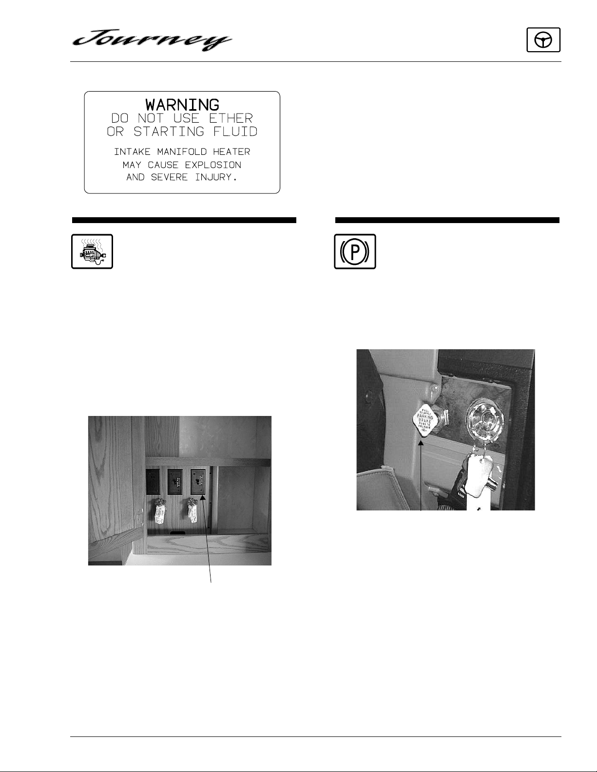
ENGINE BLOCK HEATER
Your coach is equipped with an engine block
heater to assist starting in freezing temperatures.
The power cord is located in the rear cargo compartment on the driver side of the coach. When
plugged into the receptacle, the heater is connected to both the shoreline and the auxiliary generator, so a separate extension cord is not needed.
The power switch is a standard household light
switch in the bath utility cabinet as shown.
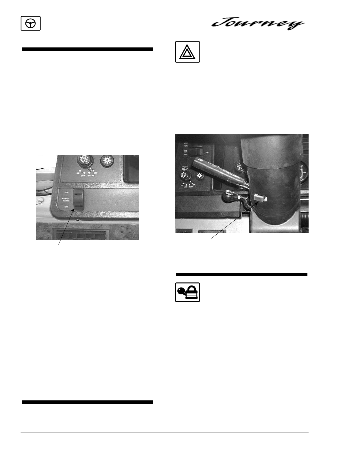
PARKING BRAKES
The parking brakes are applied by pulling outward on the large yellow knob on the dash to the
left of the ignition switch. Push the knob in to release the brakes.
Parking Brake Knob
Engine Block Heater Switch
In Cabinet to Right of Medicine Chest
To Use the Engine Heater
With the shoreline cord plugged into a shoreline hookup, turn on the engine heater power
switch.
Use the parking brakes whenever the vehicle
is parked. Never try to drive the vehicle with the
park brake applied. This can cause excessive
wear on the brakes and may damage the transmission.
NOTE: It is normal to hear an occasional burst
of air pressure from the rear of the vehicle. This is an automatic moisture purging feature of the air brake system. See
the Brakes section of your Freightliner
chassis manual for instructions on periodic draining of brake air tank.
2-3
SECTION 2
DRIVING YOUR MOTOR HOME
JACOBS® EXTARDER™ ENGINE
EXHAUST BRAKING SYSTEM
To Use the Exhaust Brake: The exhaust brake
activation switch is located on the lower left side
of the dash. Press and release the ON side of the
switch to activate the exhaust brake system. The
exhaust brake will operate whenever you let up
on the throttle pedal while the switch is ON.
Press and release the OFF side of the switch to
deactivate the exhaust brake system and return to
chassis brakes alone.
HAZARD WARNING
LIGHTS
The hazard warning flasher switch is located
on the underside of the steering column near the
signal/cruise lever. Pull the switch button outward from the column to activate the flashers. To
cancel flashers, push the switch button inward toward the column. See also Section 3 for further
operating information.
Exhaust Brake Switch
How It Works: The Jacobs® ExtarderTM is an
engine compression retarder that generates
“braking” power by controlled restriction of the
engine’s exhaust gas flow.
When the exhaust brake is activated, a valve
closes off the engine’s exhaust causing the exhaust back pressure to increase, which causes the
vehicle to slow down.
The increased back pressure would normally
stop the engine except the forward momentum of
the vehicle keeps the drivetrain and the engine
turning.
This controlled back pressure helps to regulate
a vehicle’s downhill speed, such as on mountainous or hilly roads. It also provides “braking” on
level or near-level roads.
Hazard Light Switch
Pull On/Push Off
ENTRANCE DOOR LOCK
AND HANDLE
The entrance door may be opened from outside the vehicle by pulling the door handle outward. To open the door from inside, pull outward
on the door handle. When the door is locked, neither the inside nor the outside door handle can be
operated. It can be locked and unlocked from the
outside of the vehicle by inserting the key into the
lock and turning.
2-4
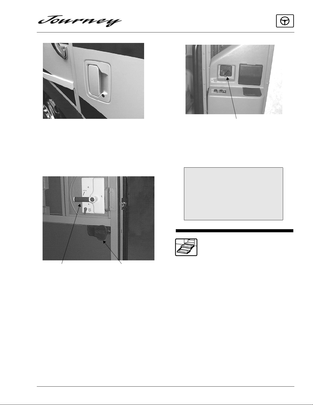
Entrance Door Handle - Outside
SECTION 2
DRIVING YOUR MOTOR HOME
Deadbolt lock
beside passenger front seat
To lock the door from inside, rotate the lock
levers as indicated. The deadbolt lock is for added security and should be used as a security night
lock.
Door Latch
Handle
Screen Door
Latch
Entrance Door Handle - Inside
Lubricate the locks periodically with graphite
to maintain good working condition.
CAUTION
When releasing security night lock,
be sure to retract bolt before opening
door latch to prevent drag on bolt pin.
Instruct all passengers in operation of
this door catch system as well as
emergency exit window.
ELECTRIC ENTRANCE
STEP
The power switch for the electric entrance step
is located to the left of the main entry door as you
enter the coach.
2-5
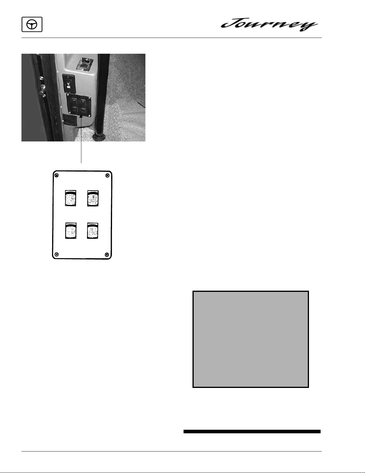
SECTION 2
DRIVING YOUR MOTOR HOME
PORCH
STEP
Entry Switch Panel
CEILING
COMPT
LAMPS
Automatic Mode (Operates with Door)
With the Power Switch in the On position the
step is in Automatic Mode. This means it will
extend and retract automatically whenever the
door is opened or closed. This is done by means
of a magnetic door switch attached to the lower
hinged edge of the screen door section of the
entrance doors. The steps will extend when the
screen door is opened, and retract when the
screen door is closed. With the power switch in
the Off position the step can be kept in the extended or retracted position as described below.
door is opened or closed. This position is normally used when parked at a campsite or whenever
people are going to be entering and exiting the
vehicle frequently.
Stationary Retracted Mode
To keep the step in the retracted position:
• turn the Power Switch to On,
• close the screen door to extend the step,
• then turn the Power Switch to Off.
The step will now stay retracted when the
screen door is open or closed. This position is
normally used where an exterior step is not required or to avoid damage to the setp, such as
when parked near a high curb or similar object.
Automatic Retraction Feature
The coach is equipped with a step retraction
feature that retracts the step automatically when
the Ignition Switch key is turned to either the On
or Start position regardless of whether the Step
Power Switch is On or Off. This feature is standard and is installed to prevent injury or damage
which may be caused by an extended step when
the vehicle is moving. An associated feature is
the “Last Out Feature”. This feature extends the
step when the screen door is opened after the
ignition switch has been turned to either the On
or Start position.
WARNING
Do not use steps unless it is fully
extended.
Do Not Stand on step when vehicles
ignition switch is turned to either the
“On” or “Start” position. The step
will automatically retract, which may
cause personal injury. Always
remember to retract the step before
moving the vehicle..
Stationary Extended Mode
To keep the step in the extended position:
• turn the Power Switch to On,
• open the screen door to extend the step,
• then turn the Power Switch to Off.
The step will now stay extended whether the
2-6
For additional information on the step, see the
step manufacturer’s operators manual included in
your Owners InfoCase.
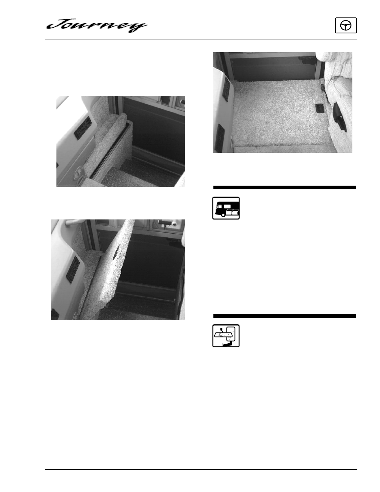
STEPWELL COVER
The stepwell cover can be positioned to cover
the stepwell area and increase usable floor space
in the front of the coach while the entrance door
is not in use.
SECTION 2
DRIVING YOUR MOTOR HOME
Step Cover 3) In-Use Position
Step Cover 1) Stored
Step Cover 2) Pull up and lower into place
LUGGAGE COMPARTMENT DOORS
To ensure that compartment doors have
latched properly, press the bottom edge of the
door with the palms of your hands. This is more
important for smaller and lighter compartment
doors because when the door is “dropped”
closed, the air trapped inside the compartment
may create a cushioning effect that could sometimes prevent door latches from engaging properly.
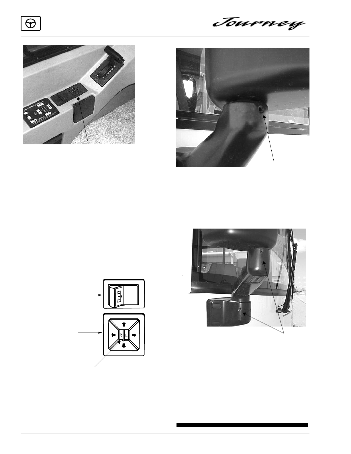
POWER ELECTRIC
MIRRORS
The electric mirrors are adjusted using a
multi-directional switch located on the driver’s
side armrest.
2-7
SECTION 2
DRIVING YOUR MOTOR HOME
Power Mirror Controls
Select the mirror to be adjusted by pushing the
switch in the middle of the control to the right or
left. Then press the arrow buttons as necessary to
obtain the best view.
When mirrors are adjusted to preference,
place the selector switch back in the middle position to cancel power to the buttons. This prevents
accidental misadjustment of mirror settings.
The mirrors also contain heating elements to
defog or de-ice the mirror glass during cold
weather operation. An ON-OFF switch for the
mirror heaters is located near the remote mirror
controls.
Mirror
Heat
Switch
Mirror
Adjustment
Control
Lock Screw
Driver Side Mirror
Loosen screw to make coarse adjustment
Lock Screws
Mirror Selector Switch:
Left for left mirror,
right for right mirror,
center off
If you cannot adjust the mirror properly using
the control switch, the mirror may need a coarse
adjustment by repositioning the mirror head. See
the mirror manufacturer’s instructions in your
Owner InfoCase.
2-8
Passenger Side Mirror
Loosen screws to make coarse adjustments
More Info
To read more about power mirrors, see the
mirror manufacturer’s information in your Owner InfoCase.
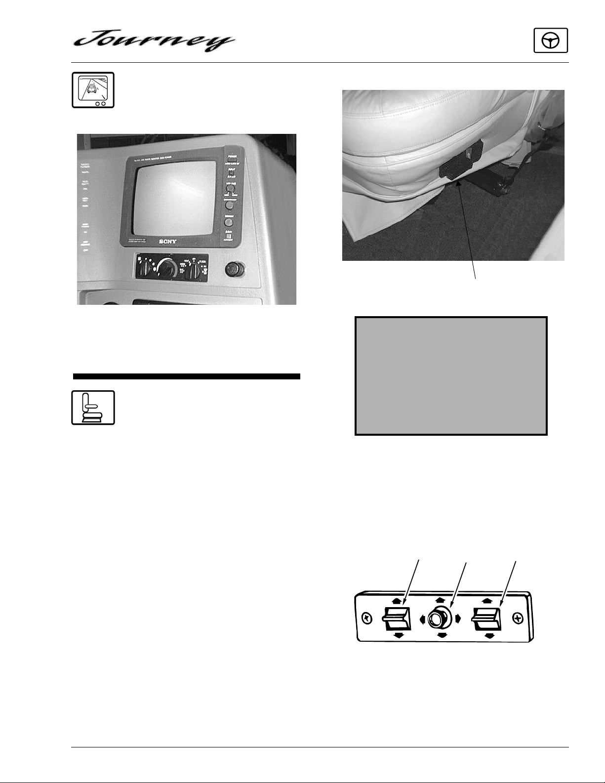
SONY REARVIEW TV
MONITOR SYSTEM
SECTION 2
DRIVING YOUR MOTOR HOME
Lever is located on lower right side of seat.
Lift to Recline
Refer to the Owner’s InfoCase for specific
instructions provided by Sony.
SEATS
The driver and co-pilot seats may be indepen-
dently adjusted to suit individual preference.
The seats may be swiveled to provide easy entrance and exit. The swivel feature also allows
the seats on some models to be turned toward the
living area for additional seating while the unit is
parked.
DRIVER SEAT
To Swivel Seat: Pull swivel release paddle out-
ward. Paddle is located on lower right side of
seat.
WARNING
Do not adjust driver’s seat while vehicle is in motion.
After adjusting seat, always use body
pressure to make sure slide and
swivel locking mechanism have
engaged.
6-Way Power Seat Controls
The power seat controls are located on the
lower right hand side of the driver seat base.
Main
Front
Up/Down
Seat
Position
Rear
Up/Down
To Recline Seat: Lift recliner release lever.
Power Seat Control
Armrest Adjustment
The armrests may be swung upward out of the
way for easy exit or access to the front seats. A
2-9
SECTION 2
DRIVING YOUR MOTOR HOME
knob at the front of the armrest also lets you adjust the resting angle for personal comfort,
whether the seat is upright or reclined.
Turn Knob to Adjust
Armrest Position
SEAT BELTS
Seats intended for occupancy while the vehicle is in motion are equipped with seat belts for
the protection of the driver and passengers. The
lap belts must be worn as low as possible and fit
snugly across the hip area. Always sit erect and
well back into the seat. To gain full protection of
the safety belt, never let more than one person use
the same safety belt at any one time, and do not
let the safety belts become damaged by pinching
them in the doors or in the seat mechanism. After
any serious accident, any seat belts which were in
use at the time should be replaced.
3
2
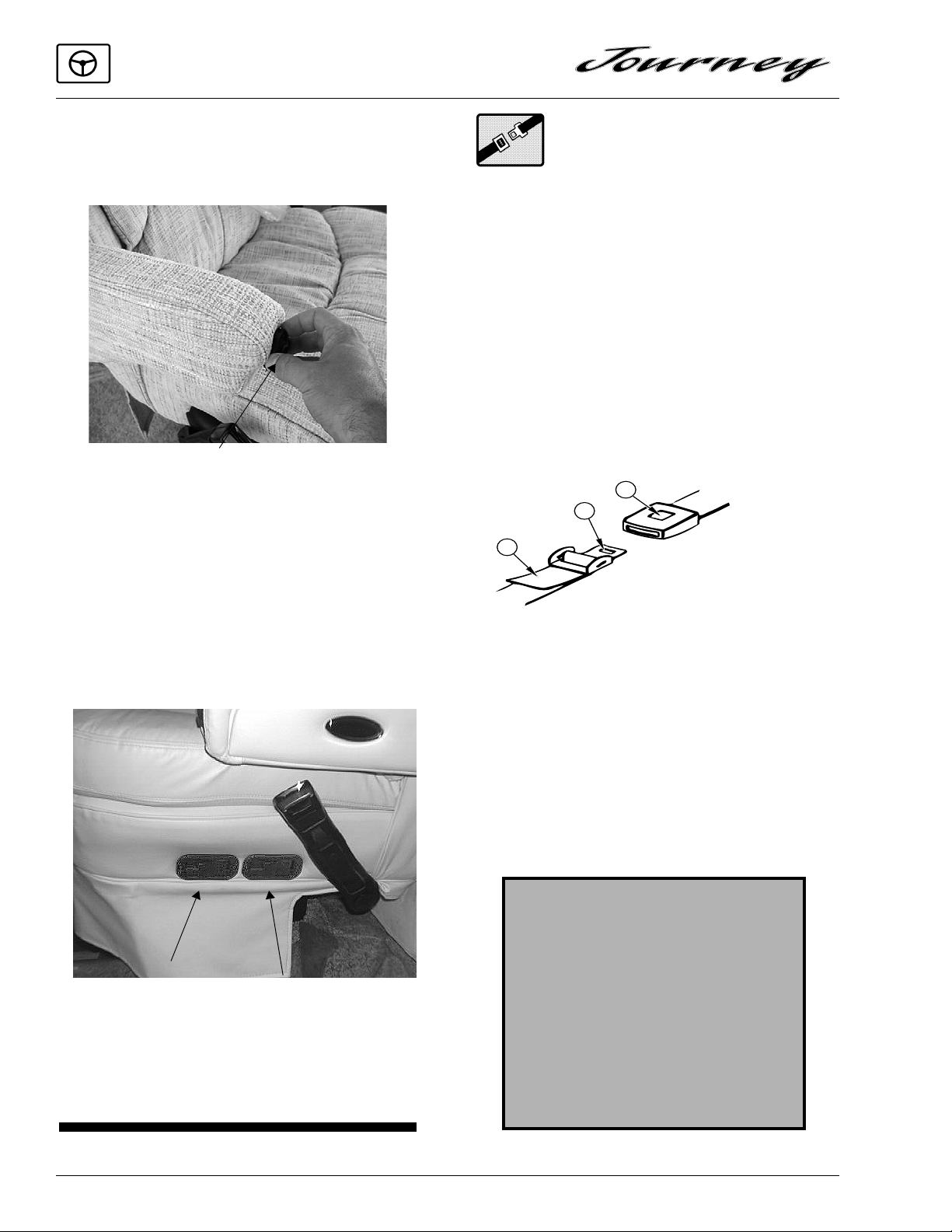
PASSENGER “BUDDY” SEAT
To Recline Seat: Pull recliner release paddle
outward. Paddle is located on lower left side of
seat.
To Slide Seat: Pull slider paddle outward. Paddle
is located on lower left side of seat.
Pull Outward
to Slide
Pull Outward
To Swivel
1
1. PULL TO TIGHTEN.
2. TONGUE.
3. PUSH TO RELEASE.
Adjustment: To lengthen belt, turn tongue at a
right angle to belt and pull to desired length. To
shorten, pull loose end of belt.
To Fasten: Be sure belt is not twisted. Grasp
each part of the belt assembly and push tongue
into buckle. Adjust to a snug fit by pulling the
loose end away from the tongue.
To Release: Press button in center of buckle and
slide tongue out of buckle.
WARNING
Snug and low belt positions are
essential. This will ensure that the
force exerted by the lap belt in a collision is spread over the strong hip area
and not across the abdomen, which
could result in serious injury.
2-10
Passenger Seat
Only seats equipped with seat belts
are to be occupied while vehicle is in
motion.
 Loading...