

Winnebago Chalet 27CR (2006), Chalet 29RR (2006), Chalet 34AR (2006), Chalet 35NR (2006), Chalet 30BR (2006) User Manual
...
TABLE OF CONTENTS
1 – SPECIFICATIONS
Tank Capacities ................................................................................................................................. 1-1
Body and Chassis Specifications ...................................................................................................... 1-2
2 – INTRODUCTION
About This Manual ........................................................................................................................... 2-1
Messages Used In This Manual ........................................................................................................ 2-1
Chassis Operating Guide .................................................................................................................. 2-2
Owner InfoCase ................................................................................................................................ 2-2
Options and Equipment .................................................................................................................... 2-2
Pre-Delivery Inspection .................................................................................................................... 2-2
Front Axle Tire Alignment ............................................................................................................... 2-2
Before Driving .................................................................................................................................. 2-3
Service and Assistance ...................................................................................................................... 2-3
Warranty ........................................................................................................................................... 2-3
Reporting Safety Defects .................................................................................................................. 2-3
Vehicle Certification Label ............................................................................................................... 2-4
3 – GETTING TO KNOW YOUR MOTORHOME
General Warnings ............................................................................................................................. 3-1
Driving .............................................................................................................................................. 3-1
Formaldehyde Information ............................................................................................................... 3-1
Carbon Monoxide Warning .............................................................................................................. 3-1
Carbon Monoxide Alarm .................................................................................................................. 3-2
Emergency Exits ............................................................................................................................... 3-2
Fire Extinguisher ............................................................................................................................... 3-3
Smoke Alarm .................................................................................................................................... 3-4
Keys .................................................................................................................................................. 3-4
Seats .................................................................................................................................................. 3-4
Seat Belts .......................................................................................................................................... 3-5
Child restraints .................................................................................................................................. 3-6
Mirrors – Exterior ............................................................................................................................. 3-7
Loading the Vehicle .......................................................................................................................... 3-7
Roof Loading .................................................................................................................................... 3-9
Tool and Ladder storage ................................................................................................................... 3-9
Storage Compartment Doors .......................................................................................................... 3-10
Mountain Driving ........................................................................................................................... 3-10
Effects of Prolonged Occupancy .................................................................................................... 3-11
Humidity and Condensation ........................................................................................................... 3-11
Prparing Vehicle for Storage .......................................................................................................... 3-11
Removal From Storage ................................................................................................................... 3-12
5 - DASH / AUTO
Rev. 0603060911 September 2006 Part No. 132000-25-006
Copyright 2006 Winnebago Industries, Inc. All rights reserved.

Table of Contents
Class A
4 – ROADSIDE EMERGENCY
If You Get a Flat Tire ....................................................................................................................... 4-1
Recovery Towing .............................................................................................................................. 4-1
Jump Starting .................................................................................................................................... 4-2
Engine Overheat ............................................................................................................................... 4-2
5 – DASH / AUTO
Instrument Panel Gauges and Controls ............................................................................................. 5-1
Headlight Beam Change and Turn Signals ....................................................................................... 5-1
Windshield Wipers and Wiper Delay ............................................................................................... 5-1
Hazard Warning Flasher ................................................................................................................... 5-1
Cruise Control ................................................................................................................................... 5-1
Rearview Monitor System ................................................................................................................ 5-1
Comfort Controls .............................................................................................................................. 5-2
Aux. Start Switch .............................................................................................................................. 5-3
In-Dash RV Radio ............................................................................................................................ 5-3
CB Radio Wiring .............................................................................................................................. 5-3
Coach Leveling Systems ................................................................................................................... 5-4
6 – APPLIANCES AND EQUIPMENT
Refrigerator ....................................................................................................................................... 6-1
Refrigerator Service Access Compartment ....................................................................................... 6-3
Range and Oven ................................................................................................................................ 6-3
Microwave Oven ............................................................................................................................... 6-5
Range Hood ...................................................................................................................................... 6-5
Systems Monitor Panel ..................................................................................................................... 6-6
Water Heater ..................................................................................................................................... 6-7
Motor Aid ......................................................................................................................................... 6-9
7 – HEATING AND AIR CONDITIONING
LP Gas Furnace ................................................................................................................................. 7-1
Thermostat Operation ....................................................................................................................... 7-2
Heat Pump ......................................................................................................................................... 7-3
Ducted Roof Air Conditioning System ............................................................................................. 7-3
8 – LP GAS SYSTEM
LP Gas Supply .................................................................................................................................. 8-1
LP Tank System ................................................................................................................................ 8-1
LP Gas Warnings and Precautions .................................................................................................... 8-1
LP Gas Leaks .................................................................................................................................... 8-2
LP Gas Alarm ................................................................................................................................... 8-2
Safe Use of the LP Gas System ........................................................................................................ 8-3
Selecting LP Fuel Types ................................................................................................................... 8-4
Refilling LP Tank ............................................................................................................................. 8-4
Air in the LP Gas Tank ..................................................................................................................... 8-5
Travel With LP Gas .......................................................................................................................... 8-5
Pressure Regulator ............................................................................................................................ 8-5

Class A
Table of Contents
9 – ELECTRICAL SYSTEMS
Electrical Cautions ............................................................................................................................ 9-1
110-Volt AC System ......................................................................................................................... 9-1
External Power Cord ......................................................................................................................... 9-1
Power Center ..................................................................................................................................... 9-2
110-Volt Circuit Breakers ................................................................................................................. 9-3
110-Volt receptacles ......................................................................................................................... 9-4
Ground Fault Circut Interrupter ........................................................................................................ 9-4
Auxiliary 110-Volt Generator ........................................................................................................... 9-4
12-Volt DC System ........................................................................................................................... 9-6
Battery Access .................................................................................................................................. 9-7
Auxiliary BatterySwitch ................................................................................................................... 9-7
DC-AC Electrical Voltage Inverter .................................................................................................. 9-8
12-Volt House Fuses and Circuit Breakers .......................................................................................9-8
Battery Stoage and Maintenance ...................................................................................................... 9-9
Battery Charge Meter ...................................................................................................................... 9-10
Aux. Start Switch ............................................................................................................................ 9-10
Electric Entrance Step ..................................................................................................................... 9-10
10 – PLUMBING SYSTEMS
Fresh Water System ........................................................................................................................ 10-1
Water Pump .................................................................................................................................... 10-1
Disinfecting Fresh Water Systems on Recreation Vehicles ........................................................... 10-2
External Water Supply (“City Water”) ........................................................................................... 10-3
Shower Hose Vacuum Breaker ....................................................................................................... 10-4
Exterior Shower/Wash Station ........................................................................................................ 10-4
Toilet ............................................................................................................................................... 10-4
Waster Water System (Holding Tanks) .......................................................................................... 10-5
Holding Tank Level Indicatiors ...................................................................................................... 10-6
Water Line and Tank Drain Valves ................................................................................................ 10-6
Water System drain Valve Locations ............................................................................................. 10-8
Winterizing Procedure .................................................................................................................. 10-10
11 – ENTERTAINMENT
In-Dash RV Radio .......................................................................................................................... 11-1
Video Selector System .................................................................................................................... 11-1
Home Theater System ..................................................................................................................... 11-2
TV Antenna ..................................................................................................................................... 11-2
Cable TV Hook-Up ......................................................................................................................... 11-3
Digital Satellite Television System ................................................................................................. 11-4
Two-Way Radios ............................................................................................................................ 11-5
12 – FURNITURE AND SOFTGOODS
Swivel Glider Lounge Chair ........................................................................................................... 12-1
Sleeping Facilities ........................................................................................................................... 12-2
Day/Nighter Pleated Blinds ............................................................................................................ 12-2
Quartz Wall Clock .......................................................................................................................... 12-3

Table of Contents
Class A
13 – SLIDEOUT ROOM
Slideout Room ................................................................................................................................ 13-1
Bedroom Slideout Emergency Retraction Procedure ..................................................................... 13-5
General Slideout Care ..................................................................................................................... 13-6
14 – CARE AND MAINTENANCE
Sealants ........................................................................................................................................... 14-1
Roof ................................................................................................................................................ 14-1
Underbody ...................................................................................................................................... 14-1
Exterior Finish ................................................................................................................................ 14-2
Headlights and Exterior Lights ....................................................................................................... 14-3
Upholstery, Carpeting and Draperies .............................................................................................. 14-3
Care of Ceiling Fabric ..................................................................................................................... 14-4
Cabinetry ......................................................................................................................................... 14-5
Vinyl Wallboard ............................................................................................................................. 14-6
Tables and Countertops .................................................................................................................. 14-6
Galley Sink ..................................................................................................................................... 14-6
Range and Refrigerator ................................................................................................................... 14-6
Bathroom ........................................................................................................................................ 14-6
Doors and Windows ........................................................................................................................ 14-7
Day/Nighter Blinds - Adjustment and Care .................................................................................... 14-7
Coach Maintenance Chart ............................................................................................................... 14-8
15 – CHASSIS
Chassis Service and Maintenance ................................................................................................... 15-1
Engine Access ................................................................................................................................. 15-1
Engine Cooling System .................................................................................................................. 15-1
Tires ................................................................................................................................................ 15-2
Suspension Alignment and Tire Balance ........................................................................................ 15-2
Front Air Springs ............................................................................................................................ 15-2
Windshield Washers and Wipers .................................................................................................... 15-2
Lights .............................................................................................................................................. 15-2
Automotive 12-Volt Fuses and Circuit Breakers ............................................................................ 15-3
Towing Guidelines .......................................................................................................................... 15-3
Car or Trailer Towing ..................................................................................................................... 15-4
Trailer Wiring Connector ................................................................................................................ 15-5

OWNER’S NAME
STREET ADDRESS
CITY AND STATE (OR PROVINCE IN CANADA)
MOTOR HOME SERIAL NUMBER
VEHICLE CHASSIS IDENTIFICATION NO. (VIN)
DATE OF DELIVERY TO FIRST RETAIL PURCHASER
VEHICLE MILEAGE AT TIME OF DELIVERY
SELLING DEALER NAME AND ADDRESS
EMERGENCY INFORMATION
YOUR WINNEBAGO INDUSTRIES DEALER
Name __________________________________________________________________________
Address _________________________________________________________________________
________________________________________________________________________________
Contact Person ___________________________________________________________________
Phone __________________________________________________________________________
CHASSIS DEALER/SERVICE CENTER
Name __________________________________________________________________________
Address _________________________________________________________________________
________________________________________________________________________________
Contact Person ___________________________________________________________________
Phone __________________________________________________________________________
INSURANCE POLICY
Company ________________________________________________________________________
Policy Number ____________________________________________________________________
Phone __________________________________________________________________________


Class A
2006 NEW VEHICLE LIMITED WARRANTY
WINNEBAGO INDUSTRIES, INC.
WARRANTY COVERAGE TO OWNER
Winnebago Industries, Inc. of Forest City, Iowa warrants each new
Winnebago Industries motor home to the owner for use in the U.S.A.
and Canada as follows:
WARRANTY PERIOD
The Warranty Period for all coverages begins on the date the vehicle
is delivered to the first retail purchaser or first placed in service as a
demonstrator or company vehicle.
BASIC COVERAGE
The basic Warranty Period is 12 months or 15,000 miles (24,135
kilometers), on the odometer, whichever occurs first. This is the only
warranty authorized by Winnebago. There are no other promises,
representations or warranties concerning the matters set forth herein.
Winnebago Industries does not authorize any person to create for it
any other obligations or liability in connection with this vehicle. ANY
IMPLIED WARRANTY OF MERCHANTABILITY OR FITNESS FOR
A PARTICULAR PURPOSE APPLICABLE TO THIS VEHICLE IS
LIMITED IN DURATION TO THE DURATION OF THIS WRITTEN
WARRANTY AS HEREINBEFORE OR HEREINAFTER PROVIDED.
THE PERFORMANCE OF REPAIRS IS THE EXCLUSIVE REMEDY
UNDER THIS WRITTEN WARRANTY OR ANY IMPLIED
WARRANTY. WINNEBAGO INDUSTRIES SHALL NOT BE LIABLE
FOR INCIDENTAL OR CONSEQUENTIAL DAMAGES FOR LOSS
OF TIME, INCONVENIENCE, OR OTHER CONSEQUENTIAL
DAMAGE INCLUDING EXPENSE FOR GASOLINE, TELEPHONE,
TRAVEL, LODGING, LOSS OR DAMAGE TO PERSONAL
PROPERTY, OR LOSS OF REVENUE RESULTING FROM
BREACH OF THIS WRITTEN WARRANTY OR ANY IMPLIED
WARRANTY. Some states do not allow limitations on how long an
implied warranty will last or the exclusion or limitation of incidental or
consequential damages, so the above limitations or exclusions may
not apply to you.
ITEMS NOT SUBJECT TO WARRANTY COVERAGE.
Chassis, Drivetrain and related components*
Wheels*
Tires*
Service Items, such as Windshield Wiper Blades, Lubricants, Fluids
& Filters
Adjustments
*These items are covered under the manufacturer’s individual
warranty.
This warranty gives you specific legal rights and you may also have
other rights which vary from state to state.
Also, this warranty shall not apply to failures, damage or
malfunctions resulting from normal wear, misuse, abuse, negligence,
alteration, accident, fire, improper repair of the vehicle or failure to
follow recommended maintenance requirements.
36 MONTHS/36,000 MILE STRUCTURAL WARRANTY
At the expiration of the Basic Coverage and for the remainder of the
period of 36 months or 36,000 miles (57,924 kilometers), on the
odometer, whichever occurs first, Winnebago Industries warrants the
following:
1. Structural defects of the subfloor, floor, and slide-out room
assembly. Floor lamination failure and lamination failure of the
subfloor panels and risers are covered by the structural
warranty.
2. Body Thermo-Panel
against delamination. Body Thermo-Panel
bonding of the exterior skin and the interior paneling to an
insulating core material. Delamination (separation of layers)
Lamination of the sidewalls and backwall
Lamination is the
caused by other factors such as physical damage or failure to
properly maintain sealants is not covered by this warranty.
WINNEBAGO INDUSTRIES’ RESPONSIBILITY
Any part of the vehicle subject to warranty which is found to be
defective in material or workmanship, will be repaired or replaced at
Winnebago Industries’ option upon notice of the defect without
charge to the customer for parts or labor. While any Winnebago
Industries motor home dealer can perform warranty service, we
recommend you return to the dealership that sold you your vehicle. If
you are touring or have moved, contact any Winnebago Industries
motor home dealer in the United States or Canada for warranty
service.
CUSTOMER RESPONSIBILITY WHEN REPAIRS ARE NEEDED
If a part of the system covered by this warranty fails to function or
requires service during the warranty period:
1. Promptly take the vehicle to the selling dealer for repair or
inspection.
2. Written notice of defects must be given to the selling dealer or
manufacturer no later than 10 days after the expiration of the
warranty.
3. If the dealer is incapable of making the repairs, request that he
contact Winnebago Industries, Inc.
4. If, after the above steps are completed and the repair is not
made, the customer should contact Winnebago Industries, Inc.,
P.O. Box 152, Forest City, Iowa 50436, Attention: Owner
Relations Department (800-537-1885) and furnish the following
information:
The complete serial number of the vehicle
Date of retail purchase
Selling dealer’s name
Nature of the service problem, and a brief explanation of the
steps or service the dealer has performed, and the results
obtained. The customer may be directed to another dealer
or service center for repairs to be completed, if such a
dealer or service center is better able to complete the
repair.
Winnebago Industries may, at its option, request the vehicle be
returned to Forest City, Iowa for repair. If the customer refuses to
allow repairs to be performed at the Forest City, Iowa facility, the
warranty on that repair will be voided.
5. If after the above steps are completed and the repairs are not
satisfactory, the customer may contact the Service
Administration Manager of Winnebago Industries, and request a
customer relations board meeting to resolve the problem. This
action, however, is not mandatory.
6. Certain components are covered beyond the 12 months/15,000
miles basic warranty coverage by the individual manufacturer’s
warranty. Please refer to the component’s information supplied
in the owner’s information InfoCase for any additional warranty
coverage after the basic warranty has expired.
DEALER’S REPRESENTATIONS EXCLUDED
Winnebago Industries, Inc. does not undertake the responsibility to
any purchaser of its products for any undertaking, representation, or
warranty made by dealers selling its product beyond those herein
expressed.
INSTALLATION NOT COVERED
Winnebago Industries, Inc. cannot , however, and does not accept
any responsibility in connection with any of its motor homes for
additional equipment or accessories installed at any dealership or
other place of business, or by any other party other than Winnebago
Industries, Inc. Such installation of equipment or accessories by any
other party will not be covered by the terms of this warranty.

CARE AND MAINTENANCE
It is the owner’s responsibility to perform the care, maintenance and
proper load distribution described in the owner’s manual which
accompanies your motor home. Any damage which results to your
vehicle as a result of your failure to perform such duties, is not
covered.
Damage to appearance items such as fiberglass, metal, paint,
fabrics and trim, may occur during manufacturing or transporting.
Normally, any factory defect or damage is corrected at the factory. In
addition, dealers are obligated to inspect each vehicle upon delivery
to them and prior to delivery to you. You should also immediately
inspect appearance items and advise your selling dealer of any
discrepancies. Damage and normal deterioration due to use and
exposure is not covered by this warranty.
CHANGES IN DESIGN
Winnebago Industries, Inc. reserves the right to make changes in
design and changes or improvements upon its products without
imposing any obligation upon itself to install the same upon its
products theretofore manufactured.
NEW YORK:
If your motor home has been repaired three or more times for the
same nonconformity, defect, or condition, or if your motor home has
been out of service by reason of repair for twenty-one days, Section
198-a of the General Business Law of the State of New York requires
you to provide written notice by certified mail, return receipt
requested, to Winnebago Industries or its authorized dealer before
making any claim under that section of the law. If you do have
problems with your motor home, you should provide written notice to
Winnebago Industries at the following address:
Winnebago Industries, Inc.
P.O. Box 152
Forest City, Iowa 50436
Atten: Owner Relations
Class A
CALIFORNIA:
Winnebago Industries participates in the Consumer Arbitration
Program for Recreation Vehicles (CAP-RV). This third-party dispute
resolution program is available, at no charge to you, to settle
unresolved warranty disputes for recreational vehicles. This dispute
resolution program reviews eligible product and service related
complaints involving warranty covered components.
To find out more about the program, or to request an
application/brochure, please call the Arbitration Administration office
toll-free 800-279-5343.
The CAP-RV program operates as a certified mechanism under the
review of the California Arbitration Certification Program. You must
utilize the arbitration program before claiming rights conferred by 15
USC section 2310 (Uniform Commercial Code) or Civil Code section
1793.22(b) (Tanner Consumer Protection Act). You are not required
to use the program if you choose to seek redress by pursuing rights
and remedies not created by those laws.
Revised 9-05

SECTION 1 – SPECIFICATIONS
TANK CAPACITIES
Chassis Fuel Tank
Model 27CR .............................................................................................................................40 gal.
Model 29RR .............................................................................................................................75 gal.
Model 30BR .............................................................................................................................75 gal.
Model 33LR .............................................................................................................................75 gal.
Model 34AR ............................................................................................................................. 75 gal.
Model 35NR ............................................................................................................................. 75 gal.
LP Gas Tank
All Models........................................................................................................ 18 gal.* (23 gal. w.c.)
Water Heater
All Models.................................................................................................................................. 6 gal.
Fresh Water Tank
Model 27CR & 30BR . . . . . . . . . . . . . . . . . . . . . . . . . . . . . . . . . . . . . . . . . . . . . . . . . . . . . . . 66 gal.
Model 29RR . . . . . . . . . . . . . . . . . . . . . . . . . . . . . . . . . . . . . . . . . . . . . . . . . . . . . . . . . . . . . . 71 gal.
Model 34AR . . . . . . . . . . . . . . . . . . . . . . . . . . . . . . . . . . . . . . . . . . . . . . . . . . . . . . . . . . . . . . 69 gal.
Model 33LR & 35NR . . . . . . . . . . . . . . . . . . . . . . . . . . . . . . . . . . . . . . . . . . . . . . . . . . . . . . . 65 gal.
HT1 - Black Water Holding Tank
Model 27CR (Toilet & Lavatory)............................................................................................. 41 gal.
Model 29RR (Toilet) ................................................................................................................37 gal.
Model 30BR (Toilet & Lavatory)............................................................................................. 41 gal.
Model 33LR (Toilet)................................................................................................................. 41 gal.
Model 34AR (Toilet) ................................................................................................................ 41 gal.
Model 35NR (Toilet) ................................................................................................................ 44 gal.
HT2 - Gray Water Holding Tank
Model 27CR (Galley & Shower).............................................................................................. 57 gal.
Model 29RR (Galley, Shower & Lavatory) ............................................................................. 42 gal.
Model 30BR (Galley & Shower).............................................................................................. 57 gal.
Model 33LR (Galley, Shower & Lavatory).............................................................................. 46 gal.
Model 34AR (Galley, Shower & Lavatory) ............................................................................. 57 gal.
Model 35NR (Galley, Shower & Lavatory) ............................................................................. 42 gal.
*LP Gas tank capacity shown is the usable “full” LP gas capacity, which is 80% of the tank manufacturer’s listed water capacity (w.c. shown in parenthesis). An LP tank must have at least 20% of tank volume free to allow for expansion and proper vaporization of the liquid fuel. The tank is also equipped with
mandatory safety shut-off equipment that prevents filling above this level.
NOTE: Capacities shown are approximate volumes based on computer design calculations. Usable
capacities may vary according to fabrication and installation of tanks and compartments.
5 - DASH / AUTO
1-1

SECTION 1
– Specifications
Class A
BODY AND CHASSIS SPECIFICATIONS
Model 27CR 29RR 30BR 33LR 34AR 35NR
Length (Bumper to Bumper) 27’ 10.6” 29’ 8” 30’ 10” 33’ 2” 34’ 6” 35’ 2”
Exterior Height (w/AC) Ford 11’ 11” 12’ 1” 11’ 9” 11’ 11” TBD 12’ 2”
Workhorse 12’ 0” 12’ 1” 11’ 11” 12’ 0” 12’ 2” 12’ 1”
Exterior Width 8’ 5 1/2” 8’ 5 1/2” 8’ 5 1/2” 8’ 5 1/2” 8’ 5 1/2” 8’ 5 1/2”
Exterior Storage (cu. ft.) 83.5 81.2 105.8 118.4 TBD 120.2
Interior Height 6’ 8” 6’ 8” 6’ 8” 6’ 8” 6’ 8” 6’ 8”
Interior Width 8’ 1/2” 8’ 1/2” 8’ 1/2” 8’ 1/2” 8’ 1/2” 8’ 1/2”
Ford
GCWR (lbs.) — 26,000 26,000 26,000 26,000 26,000
GVWR (lbs.) — 18,000 18,000 18,000 20,500 20,500
GAWR - Front (lbs.) — 7,000 7,000 7,000 7,000 7,000
GAWR - Rear (lbs.) — 11,000 11,000 11,000 13,500 13,500
Workhorse
GCWR (lbs.) 19,000 22,000 22,000 22,000 26,000 26,000
GVWR (lbs.) 15,000 18,000 18,000 18,000 20,700 20,700
GAWR - Front (lbs.) 6,000 6,000 6,000 6,000 7,500 7,500
GAWR - Rear (lbs.) 11,000 12,000 12,000 12,000 13,500 13,500
Wheelbase 168” 190” 190” 208” 228” 228”
1-2

SECTION 2 – INTRODUCTION
IMPORTANT
Before driving your vehicle, be sure you have
read the entire operator’s manual and that you
understand your vehicle’s equipment completely
and how to use the equipment safely.
NOTE:The descriptions, illustrations, and
specifications in this manual were
correct at the time of printing. We
reserve the right to change specifications
or design without notice, and without
incurring obligation to install the same
on products previously manufactured.
Congratulations! We welcome you to the
exciting world of motor home travel and
camping. You will find it convenient and
enjoyable to have all the comforts of home and
still enjoy the great outdoors wherever you
choose to go.
Your motor home has been carefully
designed, engineered and manufactured to
provide dependability as well as safety. Before
sliding into the driver’s seat, please become
familiar with operations and features. This
manual was prepared to aid you in the proper care
and operation of the vehicle and equipment. We
urge you to read it completely. In addition, spend
some time with the dealer when you take delivery
to learn all you can about your new motor home.
Read and understand all instructions and
precautions in this manual before operating your
new motor home.
included. The instructions included in this
manual are intended as a guide, and in no way
extend the responsibilities of Winnebago
Industries beyond the standard written warranty
as presented in this manual.
Please read this operator’s manual completely
to understand how everything in your coach
works before taking it on its “maiden voyage.”
This manual is a guide to safe operation of the
features, equipment and controls in this coach.
Some equipment, such as the vehicle chassis and
certain electronic systems or appliances, have
their own comprehensive, manufacturer supplied
manuals or information sheets which describe the
operation of these products in great detail. This
manual will refer you to the manufacturer’s
information included in your Owner InfoCase
whenever necessary.
We also urge you to read the complete
Chassis Operating Guide provided by the
chassis maker and all other operating
information provided by our equipment
suppliers and manufacturers. This is contained
in your Owner InfoCase.
This manual should be kept in the vehicle at
all times for personal reference. The operator’s
manual, InfoCase and chassis operating guide are
to be considered permanent components of this
vehicle. They should remain in the vehicle when
sold to provide the next owner with important
safety, operating and maintenance information.
5 - DASH / AUTO
ABOUT THIS MANUAL
This manual describes many features of your
motor home and includes instructions for its safe
use. This manual, including photographs and
illustrations, is of a general nature only. Some
equipment and features described or shown in
this manual may be optional. Because of
Winnebago Industries’ continuous program of
product improvement, it is possible that recent
product changes and information may not be
MESSAGES USED IN THIS MANUAL
Throughout this manual, certain items are
labeled Note, Caution, Warning or Danger.
These terms alert you to precautions that may
involve damage to your vehicle or a risk to your
personal safety. Read and follow them carefully.
2-1
SECTION 2
– Introduction
DANGER
DANGER indicates a directly hazardous
situation which, if not avoided, will result
in death or serious personal injury.
WARNING
WARNING indicates a potentially
hazardous situation which, if not avoided,
could result in death or serious personal
injury.
Class A
OWNER INFOCASE
The materials in your Owner InfoCase
contain warranty information and operating and
maintenance instructions for the various
appliances and components in your motor home.
Warranty registration cards for these items
should be filled out and mailed as soon as
possible after you take delivery of your motor
home. If you do not have operating instructions
for a particular appliance, contact your dealer.
OPTIONS AND EQUIPMENT
This model is available in several sizes and
floorplans, so accessories and components may
differ slightly between models. Some equipment
described in this manual may not apply to your
coach.
CAUTION
CAUTION indicates a potentially
hazardous situation which, if not avoided,
could result in damage mainly to
equipment or property, but in some cases
may also result in minor or moderate
personal injury.
NOTE: A ‘Note’ is not necessarily safety related
but indicates a recommendation or
special point of information that could
assist in understanding the use or care of
a feature item.
CHASSIS OPERATING GUIDE
Throughout this manual, frequent reference is
made to the vehicle chassis operating guide. The
chassis guide is the operator’s manual
provided by the manufacturer of the chassis on
which this motor home is built (e.g., Workhorse
or Ford). Consult the chassis guide for operating
safety and maintenance instructions pertaining to
the chassis section of the motor home.
PRE-DELIVERY INSPECTION
This motor home has been thoroughly
inspected before shipment. Your dealer is
responsible for performing a complete predelivery inspection of the chassis and all motor
home components.
As a part of the pre-delivery inspection
procedure, the dealer is responsible for road
testing the motor home; noting and correcting
any problems before delivery.
FRONT AXLE TIRE ALIGNMENT
We recommend that you have the front
suspension and steering alignment checked and
adjusted after you have fully loaded the vehicle
according to your needs. Thereafter, have
alignment inspected periodically to maintain
vehicle steering performance and prevent uneven
tire wear.
2-2

Class A
BEFORE DRIVING
Before sitting in the driver’s seat, always
check around your vehicle to be sure you have
proper clearance for maneuvering. If necessary,
have a passenger help guide you into or out of a
difficult parking space.
Although your coach features automotive
conveniences like power steering and power
brakes, driving a motor home is different than
driving a car. A motor home is larger and heavier
than an automobile, so it requires more stopping
and passing distance, and more parking and
maneuvering space than does a car.
Always be aware of the size of your motor
home. The added height of roof air conditioners,
TV antennas or luggage boxes may cause
clearance problems around some tunnels,
canopies and hanging signs. Know the height of
your unit so you can observe posted clearance
limits. Also, remember that some bridges, old
ones in particular, may not support the weight of
your motor home. Know the weight of your unit
and observe any posted weight limits.
Remember: Always use your seat belt and be
sure your passengers do so as well. We also
advise making frequent rest stops while traveling to relieve stress on yourself, your passengers
and your vehicle.
SERVICE AND ASSISTANCE
Your dealer will be glad to provide any
additional information you need, as well as
answer any questions you might have about
operating the equipment in your motor home.
When it comes to service, remember that your
dealer knows your vehicle best and is interested
in your satisfaction. Your dealer will provide
quality maintenance and any other assistance that
you may require during your ownership of this
vehicle.
If you need warranty repairs while traveling
you may take your motor home to any authorized
Winnebago or Itasca dealership and request their
assistance.
SECTION 2
– Introduction
See the dealership directory in your Owner
InfoCase.
WARRANTY
Your new vehicle is covered by a factory
warranty against defects in material and
workmanship. This warranty should be validated
immediately and returned to the factory by your
dealer. For additional information, see your
“New Vehicle Limited Warranty” included at the
front of this manual.
REPORTING SAFETY DEFECTS
If you believe that your vehicle has a defect
which could cause a crash or could cause injury
or death, you should immediately inform the
National Highway Traffic Safety Administration
(NHTSA) in addition to notifying Winnebago
Industries, Inc.
If NHTSA receives similar complaints, it may
open an investigation, and if it finds that a safety
defect exists in a group of vehicles, it may order
a recall and remedy campaign. However,
NHTSA cannot become involved in individual
problems between you, your dealer, or
Winnebago Industries.
To contact NHTSA, you may either call the
Auto Safety Hotline toll-free at 1-800-424-9393
(or 366-0123 in Washington, D.C. area) or write
to: NHTSA, U.S. Department of Transportation,
Washington, D.C. 20590. You can also obtain
other information about motor vehicle safety
from the Hotline.
2 – Introduction
2-3
SECTION 2
– Introduction
Class A
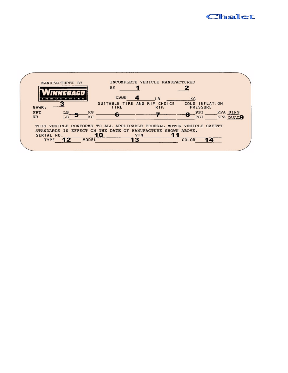
VEHICLE CERTIFICATION LABEL
This label contains vehicle identification and other important reference information. If your vehicle has a
driver door, this label is affixed to the lower inside panel of the door or on the door jamb. If your coach
does not have a driver door, the label is affixed to the armrest panel or wall to the left of the driver seat.
Explanation of Data
1. Chassis manufacturer.
2. Chassis manufacture date.
3. Month and year of manufacture at Winnebago Industries.
4. Gross Vehicle Weight Rating: Total permissible weight of the vehicle, including driver, passengers, total cargo carried (including all liquids) and equipped with all options.
5. Gross Axle Weight Rating: Total permissible weight allowed for the front and rear axles (listed in pounds and kilograms).
6. Suitable Tire Choice: Tires recommended to meet handling and safety requirements. When replacing any of the tires on your vehicle, always replace with a tire that meets these specifications.
7. Suitable Rim Choice: Wheel rims recommended to meet handling and safety requirements. When replacing any of the rims on your vehicle, always replace with a rim that meets these specifications.
8. Cold Inflation Pressure: Inflation pressures at
Gross Axle Weight Ratings recommended
(while Cold) for the tires originally equipped
on your vehicle. These pressure levels must be
maintained to assure proper handling, safety
and fuel economy.
9. Rear Axle Wheel Configuration: Single or Dual as it relates to the inflation.
10. Serial Number: This is the serial number assigned to the completed vehicle by Winnebago Industries.
11. Vehicle Identification Number (VIN): This
number identifies the chassis on which the
motor home is built. The 10th digit of the VIN
designates the chassis model year. (4=2004,
5=2005, etc.). This information is useful when
ordering chassis repair parts.
12. Type: States the NHTSA designated usage classification for your motor home. MPV signifies a Multi-purpose Passenger Vehicle.
13. Model: Lists the Winnebago product model number of your vehicle.
14. Color: Signifies the color code number of the decor used throughout the vehicle. This number is necessary for ordering replacement cushions, curtains, carpet, etc.
2-4
SECTION 3 – GETTING TO KNOW YOUR MOTORHOME
Read and understand all instructions and
precautions in this manual before operating your
new motor home.
GENERAL WARNINGS
• Only seats equipped with seat belts are to be
occupied while the vehicle is moving.
• Make sure all passengers have seat belts
fastened in a low and snug position so the
force exerted by the belt in a collision will be
spread across the strong hip area. Pregnant
women should wear a lap-shoulder belt
whenever possible.
• All moveable or swiveling seats should be
placed and locked in forward facing positions
while the vehicle is moving.
• Never let passengers stand or kneel on seats
while the vehicle is moving.
• Sleeping facilities are not to be utilized while
vehicle is moving.
• Examine the escape window and be familiar
with its operation.
• Ιnspect the fire extinguisher monthly for
proper charge and operating condition. This
should also be done before beginning a
vacation or any extended trip.
DRIVING
• Driving through water deep enough to wet the
brakes may affect stopping distance or cause
the vehicle to pull to one side. Check brake
operation in a safe area to be sure they have
not been affected. Never operate any vehicle
if a difference in braking efficiency is
noticeable.
• Adverse weather conditions and extremes in
terrain may affect handling and/or
performance of your vehicle. Refer to your
chassis manual for related information.
FORMALDEHYDE INFORMATION
WARNING
Some components in this vehicle contain
formaldehyde based adhesives which
may release formaldehyde fumes into the
air for an unknown period of time until total
dissipation occurs. Individuals who are
allergic to formaldehyde gas fumes may
experience irritation to eyes, ears, nose
and throat. Reaction in infants may be
more severe. Although long range effects
are not well understood, testing to date
has not revealed any serious health
effects in humans at the level of emission
from these products.
5 - DASH / AUTO
• Do not attempt to adjust the driver’s seat while
the vehicle is moving.
• Do not adjust tilt steering in a moving vehicle.
• Do not operate the cruise control on icy or
extremely wet roads, winding roads, in heavy
traffic, or in any other traffic situation where
a constant speed cannot be maintained.
• Use care when accelerating or decelerating on
a slippery surface. Abrupt speed changes can
cause skidding and loss of control.
CARBON MONOXIDE WARNING
WARNING
Avoid inhaling exhaust gases, as they
contain carbon monoxide, which is a
colorless, odorless and poisonous gas.
3-1
SECTION 3
– Getting To Know Your MotorHome
The best protection against carbon monoxide
entry into the vehicle body is a properly
maintained engine exhaust and ventilation
system. It is recommended that the exhaust
system and body be inspected by a qualified
motor home service center.
• Each time the vehicle is serviced for an oil
change.
• Whenever a change in the sound of the
exhaust system is noticed.
• Whenever the exhaust system, underbody or
rear of the vehicle is damaged.
To allow proper operation of the vehicle’s
ventilation system, keep front ventilation inlet
grill clear of snow, leaves or other obstructions at
all times. DO NOT OCCUPY A PARKED
VEHICLE WITH ENGINE RUNNING FOR
AN EXTENDED PERIOD.
Do not run engine in confined areas, such as a
garage, except to move vehicle into or out of
area.
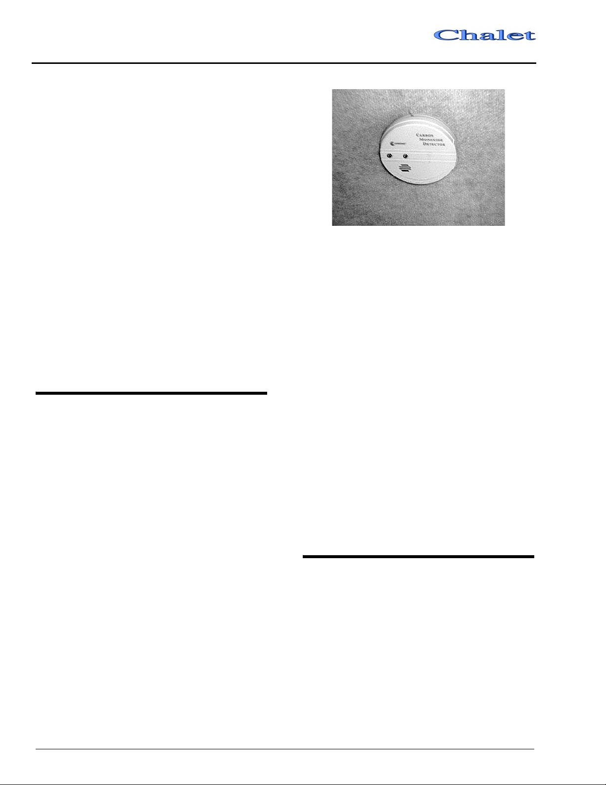
CARBON MONOXIDE ALARM
Your coach is equipped with a carbon
monoxide (CO) alarm located on the ceiling in
the bedroom area. The CO alarm is powered by a
9-volt battery and has a sensor that is designed to
detect toxic carbon monoxide gas fumes
resulting from incomplete combustion of fuel. It
will detect CO gas from any combustion source
such as the furnace, gas range/oven, water heater,
refrigerator, chassis engine, and electric
generator engine.
Class A
Carbon Monoxide Alarm
Monthly Testing
Press the TEST button on the face of the alarm
at least monthly to check the function of the
alarm and condition of the battery. If the alarm
begins to beep every few seconds, the battery
may be weak and need replacement. (Press the
TEST button to be sure before replacing the
battery. If the alarm sounds, the battery may still
be okay. If the alarm still beeps every few
seconds, check the smoke detector also. The “low
battery” warning beep is similar on many alarm
devices, so the origin of this electronic sound can
be deceiving.)
Further Information
Please read the information provided by the
manufacturer, which is included in your Owner
InfoCase. It includes information on precautions,
operational testing, and battery/sensor
replacement.
3-2
EMERGENCY EXITS
Instructions for operation are also located on a
label on the glass for quick reference and for
passengers who may not be familiar with the exit.
Never remove or destroy this label.
Class A
SECTION 3
– Getting To Know Your MotorHome
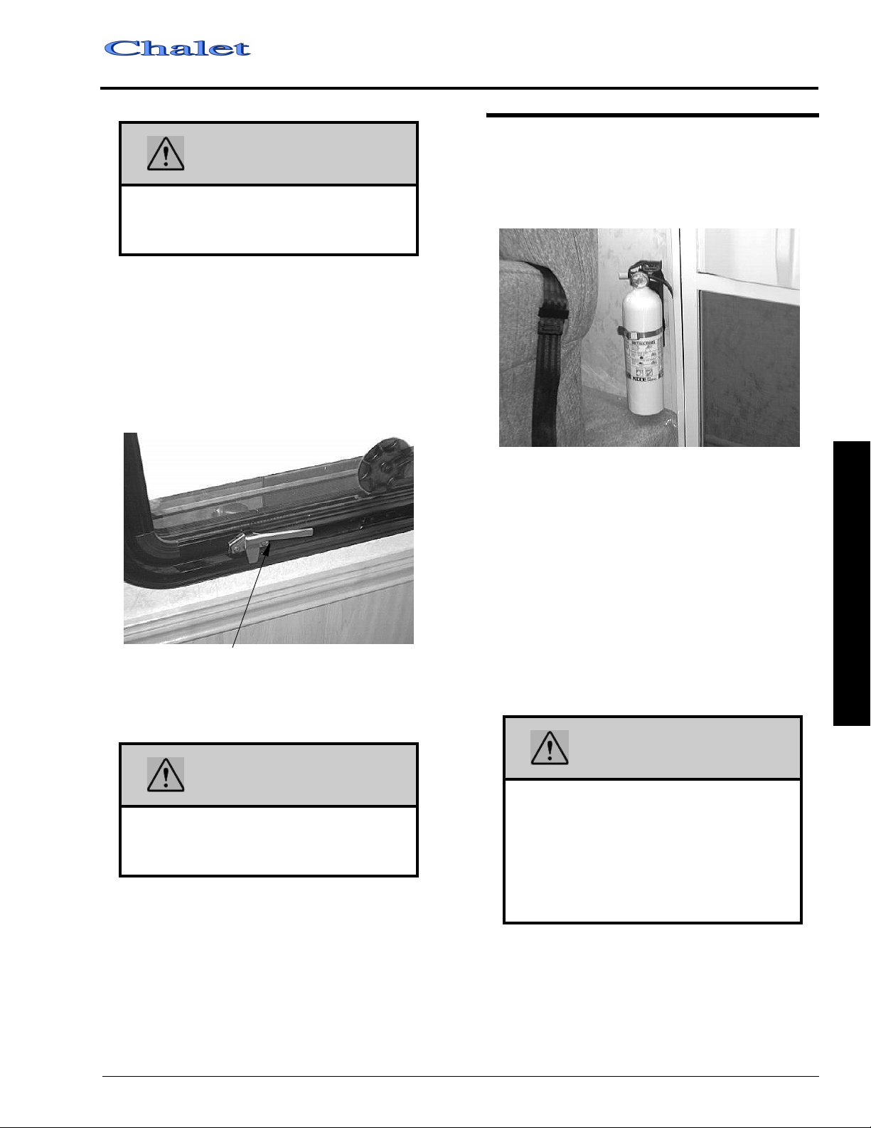
FIRE EXTINGUISHER
WARNING
Use care when exiting emergency
window, as broken glass may be present
in the exit area.
Swing-Out Side Escape Window
The bedroom side escape window is secured
by two red safety latches at the bottom of the
window.
To open, lift both latches up and toward the
center of the window, then push outward near the
bottom of the window.
Lift latch handles upward to open.
Escape Window
A dry chemical fire extinguisher is located
near the main entrance door.
We recommend that you become thoroughly
familiar with the operating instructions displayed
on the side of the fire extinguisher or in the
information supplied in your Owner InfoCase.
We also recommend that you inspect the fire
extinguisher for proper charge at least once a
month in accordance with National Fire
Protection Association (NFPA)
recommendations as stated on the label.
If the charge is insufficient, the fire
extinguisher must be replaced.
3 – Getting To Know Your MotorHome
WARNING
This window should be kept closed while
driving to avoid drawing dangerous
exhaust gases into the vehicle.
Using Slider Windows As Emergency Exits
Most slider windows along the side of the
motor home can also be used as emergency exits,
should the need arise. To use the windows as
exits, first slide the window open, then slide the
screen open or push the screen material out,
depending on window type.
WARNING
Do not test the fire extinguisher by
discharging it. Partial discharge can
cause leakage of pressure or contents
which would render the unit inoperative
when needed. When using the fire
extinguisher, aim the spray at the base of
the fire.
3-3
SECTION 3
– Getting To Know Your MotorHome
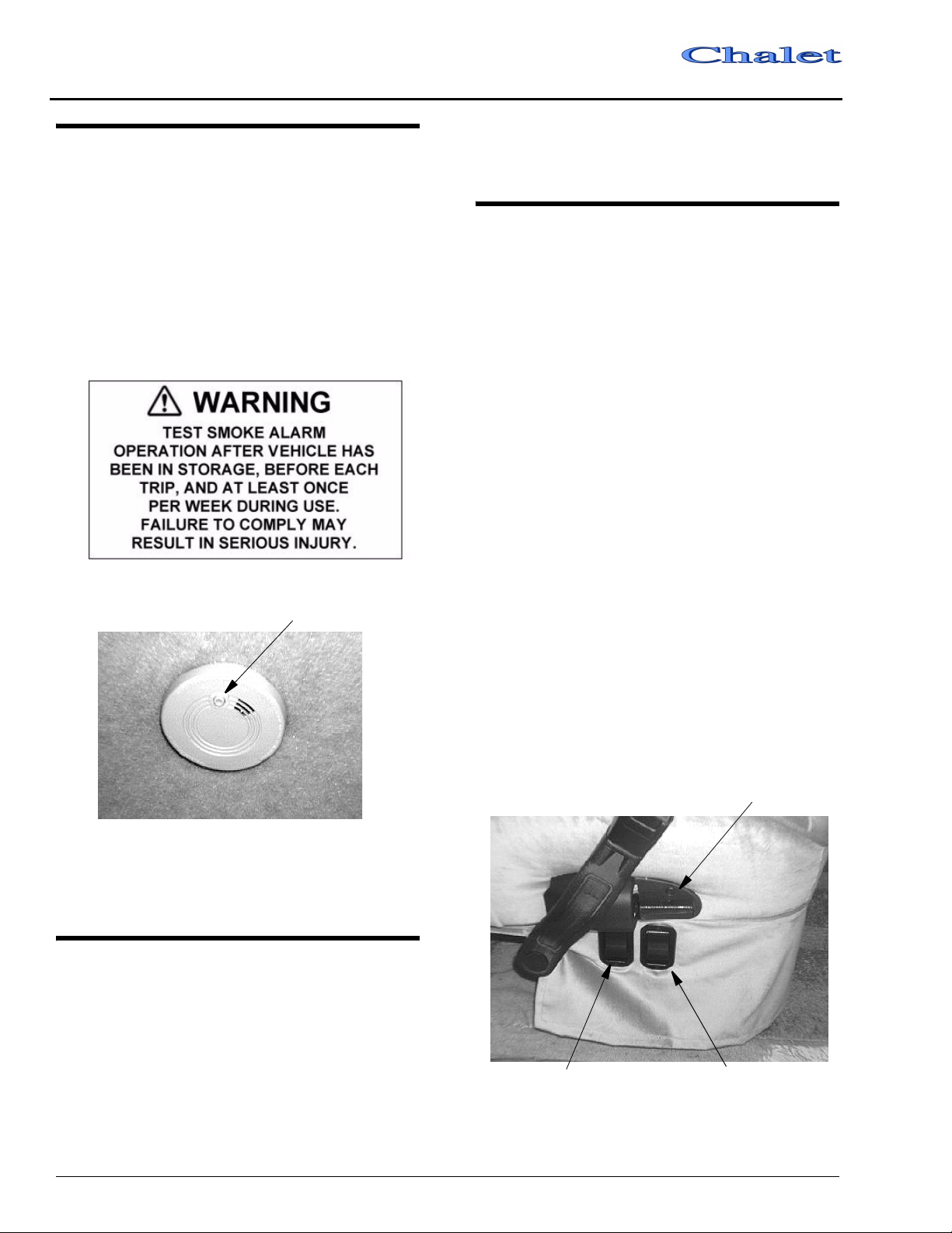
SMOKE ALARM
Your motor home is equipped with a smoke
alarm located on the ceiling in the galley area.
This alarm meets U.L. Standard 217 and NFPA
Standard 74 for operation of smoke detection
devices.
The following label is affixed either to the
smoke alarm or on the ceiling near the smoke
alarm.
Class A
in your Owner InfoCase. In case keys are lost or
stolen, your dealer or a locksmith can provide
you with duplicate keys or modify the locks.
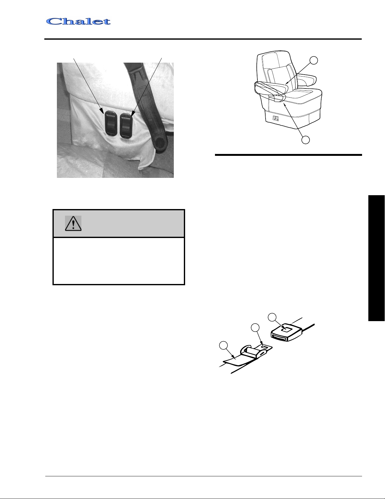
SEATS
The driver and co-pilot seats may be
independently adjusted to suit individual
preference. To move the seat forward or
backward, lift the slide release paddle, located on
the side of the seat, and exert slight body pressure
in the direction desired.
The seats may be swiveled to provide easy
entrance and exit. The swivel feature also allows
the seats on some models to be turned toward the
living area for additional seating while the unit is
parked.
Press button to test
Smoke Alarm
See your Owner Infocase for further
information.
KEYS
To Swivel the Seats
Lift the release lever, located on the side of the
seat, and rotate seat. The seats are designed to
lock only when returned to the forward facing
position.
To Recline the Seats
Lift the reclining lever, lean back to desired
incline and release the lever. To return to the
upright position, lift the lever and lean body
forward. Allow the seat to return to the desired
position and release the lever.
Lift to Recline
Your motor home is supplied with several sets
of keys. In addition to the chassis manufacturer's
ignition key, you receive keys for the entrance
door and exterior compartment doors.
Keys have an identification number, either a
small metal tag or stamped into the key head.
These numbers are recorded on the vehicle’s
component model/serial sheet which is included
3-4
Lift to Swivel
Driver Seat - Aisle Side
Lift to Slide
Class A
f
t to Slide
Li
(Recline lever on opposite side)
Lift to Swivel
Passenger Seat - Aisle Side
SECTION 3
– Getting To Know Your MotorHome
1
2
SEAT BELTS
Seats intended for occupancy while the
vehicle is in motion are equipped with seat belts
for the protection of the driver and passengers.
Lap Belts
The lap belts must be worn as low as possible
WARNING
Do not adjust driver’s seat while vehicle is
in motion.
After adjusting seat, always use body
pressure to make sure slide and swivel
locking mechanism have engaged.
Arm Rest Adjustment
The driver and co-pilot seat armrests may be
adjusted to rest at two different positions as
shown.
Position 1 - Raise armrest, push in toward seat,
and lower into position. This position would
generally be used when the seat is in the
upright position.
Position 2 - Raise armrest, pull outward from
seat, and lower into position. You may wish
to use this position when you recline the seat.
and fit snugly across the hip area. Always sit
erect and well back into the seat. To gain full
protection of the safety belt, never let more than
one person use the same safety belt at any one
time, and do not let the safety belts become
damaged by pinching them in the doors or in the
seat mechanism. After any serious accident, any
seat belts which were in use at the time should be
replaced.
3
2
1
1. PULL TO TIGHTEN.
2. TONGUE.
3. PUSH TO RELEASE.
Adjustment: To lengthen belt, turn tongue at a
right angle to belt and pull to desired length.
To shorten, pull loose end of belt.
To Fasten: Be sure belt is not twisted. Grasp
each part of the belt assembly and push
tongue into buckle. Adjust to a snug fit by
pulling the loose end away from the tongue.
To Release: Press button in center of buckle and
slide tongue out of buckle.
3 – Getting To Know Your MotorHome
3-5

SECTION 3
– Getting To Know Your MotorHome
WARNING
Snug and low belt positions are essential.
This will ensure that the force exerted by
the lap belt in a collision is spread over the
strong hip area and not across the
abdomen, which could result in serious
injury.
Only seats equipped with seat belts are to
be occupied while vehicle is in motion.
Lap-Shoulder Belts
Fastening: Hold the belt just behind the
tongue using the hand nearest to the door. Next,
bring the belt across the body and insert the
tongue into the buckle until the latch engages.
Unfastening: Press the release button in the
buckle. Hold onto the tongue when you release it
from the buckle to keep it from retracting too
rapidly.
When the lap-shoulder belt is in use, the lap
belt must ride low across the hip area and the
shoulder belt must ride diagonally over the
shoulder toward the buckle.
The shoulder belt is designed to lock only
during a sudden stop, sudden body movement or
a collision. At all other times it will move freely
with the occupant.
WARNING
Never wear the shoulder belt in any
position other than as stated above.
Failure to do so could increase the
chance or extent of injury in a collision.
Seat Belt Care and Cleaning
• Be careful not to damage the belt webbing and
hardware. Take care not to pinch them in the
seat or doors.
Class A
• Inspect the belts and hardware periodically.
Check for cuts, frays, and loose parts.
Damaged parts should be replaced. Do not
remove or modify the belt system.
• Keep belts clean and dry. If the belts need
cleaning, use only a mild soap and water
solution. Do not use hot water. Do not use
abrasive cleaners or bleach. These products
may weaken or damage the belts.
• Replace any belt assembly that was used
during a severe impact. Replace the complete
assembly even if damage is not apparent.
CHILD RESTRAINTS
A properly installed and secured child
restraint system can help reduce the chance or
severity of personal injury to a child in an
accident or during a sudden maneuver. Children
may be injured in an accident if they are not
seated in a child restraint which is not properly
secured.
A child restraint system is designed to be
secured in a vehicle seat by a lap belt or the lap
belt portion of a lap-shoulder belt. According to
accident statistics, children are also safer when
properly restrained in rear seating positions than
in front seating positions.
When purchasing a child restraint system:
1. Look for the label certifying that it meets all
applicable safety standards.
2. Make sure that it will attach to your vehicle
and restrain your child securely and
conveniently so that you are able to install it
correctly each time it is used.
3. Be certain that it is appropriate for the child's
height, weight and development. The
instructions and/or the regulation label
attached to the restraint typically provides this
information.
4. Review the instructions for installation and
use of the restraint. Be sure that you
understand them fully and can install the
restraint properly and safely in your vehicle.
3-6
Class A
SECTION 3
– Getting To Know Your MotorHome
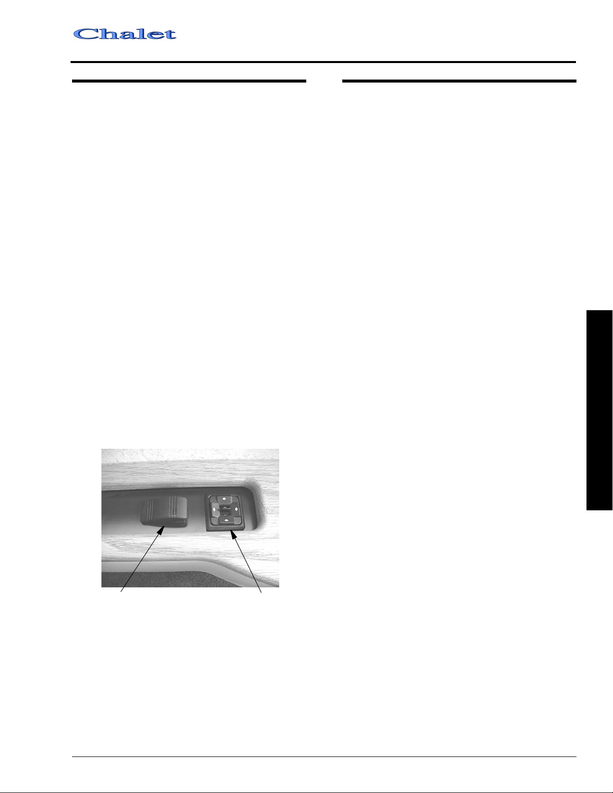
MIRRORS – EXTERIOR
Always adjust mirrors for maximum rear
visibility before driving off. Make sure the seat is
adjusted for proper vehicle control and that you
are sitting back squarely into the seat.
Power Electric Mirrors - Optional
The electric mirrors are adjusted using a
multi-directional switch located on the armrest
panel to the left of the steering column.
Select the mirror to be adjusted by pushing the
switch in the middle of the control to the right or
left. Then press the arrow buttons as necessary to
obtain the best view.
When mirrors are adjusted to preference,
place the selector switch back in the middle
position to lock-out power to the buttons. This
prevents accidental misadjustment of mirror
settings.
The mirrors also contain heating elements to
defog or de-ice the mirror glass during cold
weather operation. An ON-OFF switch for the
mirror heaters is located near the remote mirror
controls.
Mirror Heat
Switch
The power mirror control switch is intended
for fine adjustment of the mirrors. If you cannot
adjust the mirror properly using the control
switch, the mirror may need a coarse adjustment
by repositioning the mirror head. See the mirror
manufacturer’s instructions in your Owner
InfoCase.
Mirror Adjustment
Switch
LOADING THE VEHICLE
NOTE: Your motor home’s load capacity is
designated by weight, not by volume, so
you cannot necessarily use all available
space when loading your motor home.
• Store or secure all loose items inside the motor
home before traveling. Possible over- looked
items such as canned goods or small
appliances on the countertop, cooking pans on
the range, or free-standing furniture items can
become dangerous projectiles during a
sudden stop or evasive maneuver.
• Be aware of GVWR, GAWR and individual
load limit on each tire or set of duals.
When loading the vehicle, distribute the cargo
load equally so that you do not exceed either the
Front or Rear Gross Axle Weight Rating
(GAWR) or the Gross Vehicle Weight Rating
(GVWR). The Gross Axle Weight Rating
(GAWR) means the weight value specified by
the chassis manufacturer as the load carrying
capacity of a single axle system as measured at
the tire-to-ground interfaces. This is the total
weight a given axle is capable of carrying. Each
axle has its own rating.
Have your vehicle weighed to determine the
proper load distribution for your vehicle. Also
distribute cargo side-to-side so the weight on
each tire or dual set does not exceed one half of
the GAWR for either axle.
For example, if the Front GAWR is 6,000 lbs.,
there should be no more than 3,000 lbs. on each
tire. (If the left side weighs 3,100 lbs. and the
right side weighs 2,700 lbs., at least 100 lbs. of
the load should be shifted from the left side to the
right side.) The GVWR is listed on the Vehicle
Certification Label. (See sample in Introduction
Section).
The GCWR (Gross Combination Weight
Rating) means the maximum allowable loaded
weight of this motor home and any towed trailer
or towed vehicle. If trailer towing is not
recommended, the GCWR will equal the
GVWR.
3 – Getting To Know Your MotorHome
3-7
SECTION 3
– Getting To Know Your MotorHome
NOTE: We recommend that you dump all
holding tanks before traveling to avoid
carrying unnecessary weight.
CAUTION
Class A
The weight of the loaded vehicle
(including options, attachments,
passengers, water, fuel, luggage and all
other cargo) must not exceed the GVWR
or GAWR of either axle.
Weighing Your Loaded Vehicle
To check the weight of your fully loaded
coach, locate a commercial weighing scale that is
capable of weighing large trucks.
Loading: Load your vehicle completely as if
you were going on a long trip, with everything
you would carry, including food, clothing, bedding, lawn chairs, etc., a full fuel tank, full LP
tank, and a partial tank of fresh water - but
empty holding tanks.
Finding a Scale: In urban areas, the most common places to find a public access scale are commercial truck stops. In rural areas, most grain
storage elevators have scales available. If you
don’t know of a truck scale in your area, look in
the Yellow Pages for entries such as Grain Elevators, Scales-Public, Truck Stops, Weigh Stations, etc. If you cannot locate a scale in your
area, call your state DOT and ask for recommendations. Most scales charge a nominal fee for
weighing a vehicle.
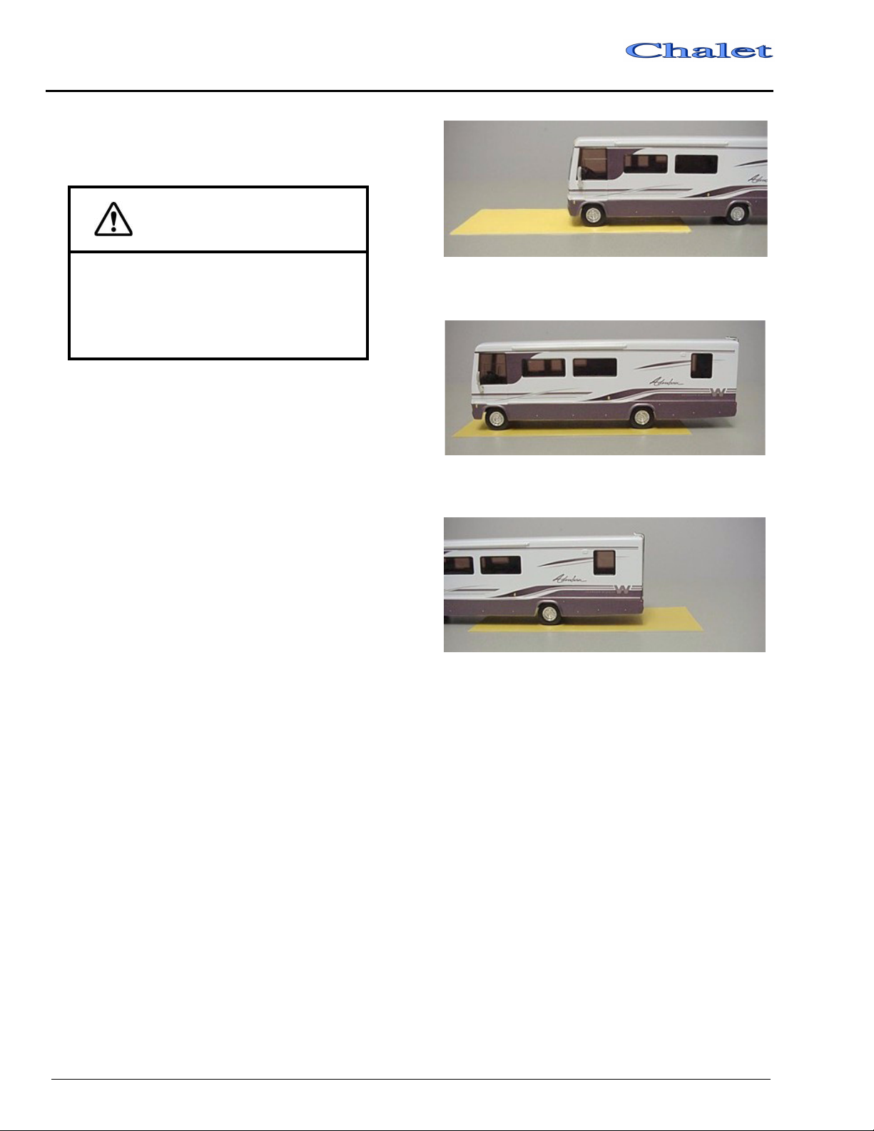
Weighing: There is typically a scale operator to
direct you but the basic routine is to take three
separate weights - front axle, whole vehicle, and
rear axle. You will first drive only your front
wheels onto the scale pad, then drive ahead so
that the whole vehicle is on the scale, then
finally pull off until just the rear wheels are on
the pad.
Front GAWR (Front Axle Only)
GVWR (Both Front and Rear Axles)
Rear GAWR (Rear Axle Only)
You will receive a weight ‘ticket’ that states
your current Front Gross Axle Weight, Rear
Gross Axle Weight and Gross Vehicle Weight.
You can compare these weights to the weight
ratings listed on your Vehicle Certification Label
to use as a guideline for future loading limits and
weight distribution.
The gross weight of the vehicle should not
exceed the Gross Vehicle Weight Rating
(GVWR) specified on the Vehicle Certification
Label. (see section 2). The front and rear axle
weight also should not exceed the corresponding
Axle Weight Rating specified on the Vehicle
Certification Label.
3-8
Class A
SECTION 3
– Getting To Know Your MotorHome
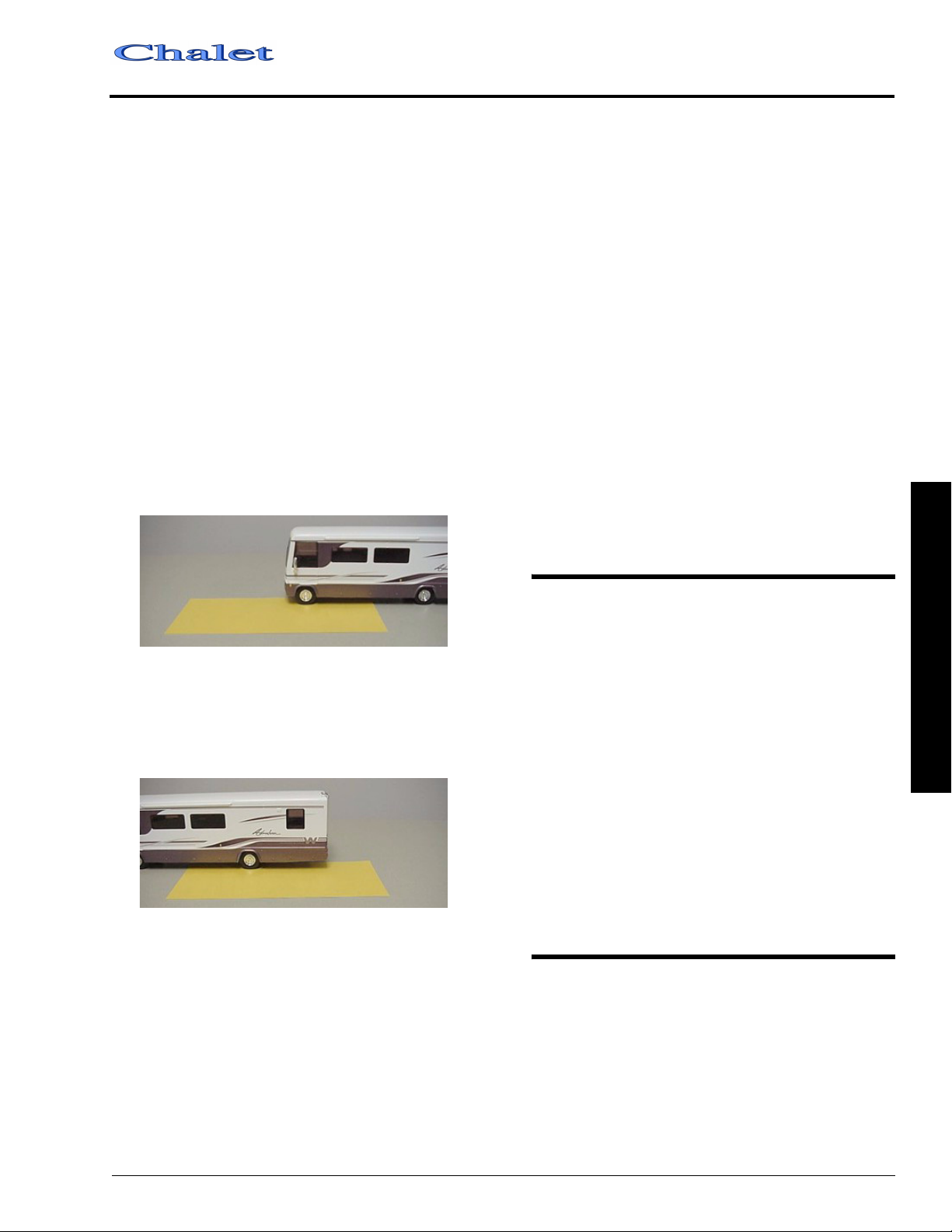
Corner Weighing (Side-to-Side)
Weighing each corner of the coach separately
(single L/R front wheels or L/R rear dual sets) is
an accurate method to determine how to
distribute your cargo to avoid overloading,
especially on tires.
To determine the weight distribution on each
tire or dual set, you will need to find a scale
capable of weighing side-to-side, or all four
‘corners’ of the vehicle, separately. A truck scale
may be used if the ground is level with the scale
surface and the scale has clearance to drive one
side of the coach onto the scale as shown below.
Drive the coach on the level area next to the
scale and straddle the scale so that only one side
of the coach will be on the scale pad. Pull only the
front wheel onto the pad as shown.
Tires should be filled to the recommended air
pressure for the highest loaded tire set on that
axle. For example, on the rear axle, if the left
side weighs more than the right, fill the left tires
to the pressure required for that weight, then fill
the right tires to the same pressure as the left
ones.
If your actual weight is considerably less than
GAWR rating, you may be able to lower your
tire pressure. See a tire dealer for a load/pressure
chart.
NOTE: The Hitch Load from a Towed Vehicle or
carrier box must also be counted on the
Rear GAWR and subtracted from the
rear axle cargo capacity.
Be aware that hitch load can affect handling
characteristics. The more weight on the hitch, the
lighter the front end will feel at the steering
wheel.
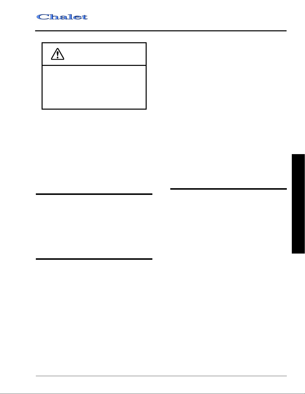
Weighing Left Front ‘Corner’
When the front wheel has been weighed, pull
the coach straight ahead until only the rear wheel/
dual set is on the scale pad as shown.
Weighing Left Rear ‘Corner’
After the rear wheel set has been weighed, turn
the coach around and repeat this process for the
other side.
The load on each wheel or dual-wheel set should
not exceed one-half of the corresponding
GAWR. For example, if the GAWR for the rear
axle is 12,000 lbs., then the load on each rear
dual set (left rear duals or right rear duals)
should not exceed 6,000 lbs.
ROOF LOADING
The roof is capable of carrying some
lightweight articles while the vehicle is in
motion. A roof-mounted luggage carrier
designed for this purpose is available from your
dealer. However, roof load while the vehicle is in
motion is not to exceed 10 pounds per square foot
or a maximum of 100 pounds.
When the vehicle is stationary, a cargo load of
100 pounds plus the weight of a 225 pound
person to load the cargo or to conduct inspection
and maintenance is permissible.
Weight added to both the roof and the trailer
hitch contribute to the gross vehicle weight,
which must not exceed the vehicle’s GVWR.
TOOL AND LADDER STORAGE
The roof ladder extension and various
supplied tools are stored in clips on the walls of
one or two of the exterior storage compartments.
Actual locations depend on storage compartment
configuration of your model. The following
photos show typical arrangements.
3 – Getting To Know Your MotorHome
3-9

SECTION 3
– Getting To Know Your MotorHome
Tire Tools
Class A
Awning
Stakes
Slideout Emergency
Cranks
Wheel
Liner Tool
Awning
Hook
Ladder Extension
Ladder Extension
To use the ladder extension:
• Unfold the bumper support and pin into place
as indicated on the following photo.
• Hold the ladder extension horizontally with
the bumper pad pointing downward.
• Slide the open ends of the C-shaped retainers
over the lowest ladder rung as shown in the
photo.
• Lower the extension into place and push
downward while wiggling it slightly to ‘seat’
the retainers.
• The ladder is now ready to use.
STORAGE COMPARTMENT DOORS
To ensure that exterior storage compartment
doors have latched properly, press firmly on the
bottom edges of the doors with the palms of your
hands. If the door is ajar you will hear and feel a
loud ‘click’ when the latches engage properly.
The high-density gaskets used on the exterior
storage compartments are designed to provide a
more positive seal against dust and weather.
Sometimes this seal firmness can inhibit
complete latching of the compartment doors if
they are simply ‘dropped shut’ or closing force is
applied only to the center of the door.
MOUNTAIN DRIVING
Special techniques must be used when driving
in mountainous or hilly country.
Climbing A Hill
The transmission will automatically
downshift as needed to climb most hills. If the
hill is long or very steep, however, you may need
to manually shift to a lower gear to keep the
transmission from repeatedly upshifting and
downshifting. Select the lowest adequate gear
range for the duration of the incline. See your
chassis operating guide for specific information.
• Reverse steps to remove and store.
3-10
Class A
CAUTION
Observe the engine temperature gauge
more frequently than normal. If
overheating occurs, pull off to the side of
the road and allow the engine to
thoroughly cool before refilling the
radiator and restarting the engine.
Descending A Hill
When going down a long grade, you may need
to manually shift to a lower gear rather than
keeping your foot on the brake pedal. A lower
gear will allow the engine to provide a degree of
braking action. Holding your foot on the brake
pedal for an extended period may cause brakes to
overheat, which could cause you to lose control
of the vehicle. See your chassis operating guide
for specific information.
SECTION 3
– Getting To Know Your MotorHome
You can help reduce excessive moisture
inside the motor home by taking the following
steps:
Ventilate With Outside Air:
Partially open one or more windows and a
roof vent to circulate outside air through the
coach. In cold weather, this ventilation may
increase use of the furnace, but it will greatly
reduce the condensation inside the coach.
Minimize Moisture Released Inside The Coach:
Run the range hood fan while cooking, and
open a bath vent while bathing or showering to
carry water vapor out of the coach. Avoid making
steam from boiling water excessively or letting
hot water run. Avoid bringing extra moisture into
the coach by way of soaked clothing or snow on
shoes. Do not hang-dry wet overcoats or clothing
inside the coach.
EFFECTS OF PROLONGED OCCUPANCY
Your motor home was designed primarily for
recreational use and short term occupancy. If you
expect to occupy your coach for an extended
period, be prepared to deal with condensation and
humid conditions that may be encountered.
HUMIDITY AND CONDENSATION
Moisture condensing on the inside of
windows is a visible indication that there is too
much humidity inside the coach. Excessive
moisture can cause water stains or mildew which
can damage interior items such as upholstery and
cabinets.
When you recognize the signs of excessive
moisture and condensation in your coach, you
should take immediate action to minimize their
effects.
PRPARING VEHICLE FOR STORAGE
Properly preparing your vehicle for storage
will lessen the possibility of damage to your
vehicle. Prepare the motor home for vacancy just
as you would if you were leaving your house for
an extended period:
3 – Getting To Know Your MotorHome
Clean and Prep Coach for Storage
1. Turn off the LP gas tank.
2. Turn the furnace thermostat switch OFF.
3. Remove all foods and items that may cause
odors from cabinets and refrigerator.
4. Clean and defrost the refrigerator. Prop the
door open slightly to allow any odors to
dissipate. Place an open box of baking soda
inside the refrigerator to help absorb odors.
5. Fully charge the batteries. Batteries must
have at least 80% charge to survive
freezing temperatures and long period of
non-use. We recommend that you connect a
battery charger or plug in the shoreline once a
month during long-term storage periods to
maintain battery charge and to avoid
3-11

SECTION 3
– Getting To Know Your MotorHome
Class A
sulfating. If connecting a charger directly to
batteries, turn the Aux. Battery switch off to
avoid electrical arcing when attaching and
detaching charger clamps.
6. After charging batteries, turn the Aux. Battery Switch off to disconnect the batteries and avoid parasitic* drain.
7. Have the vehicle chassis completely serviced and lubricated. Be sure radiator antifreeze protection level is sufficient for the lowest anticipated temperatures.
8. Wash and wax the coach.
9. Inspect all seams and seals around doors,
windows, vents, and any other joints. Replace
or repair any that are damaged. Sealing
materials and compounds can be purchased
from your dealer. Badly damaged weather
seals may need to be replaced by your dealer.
10. Close all windows and roof vents. Protect all appliance vent openings from contamination by animals or insects (e.g. bird nests, wasp nests, etc.)
11. Lubricate all door hinges and locks.
12. Clean the interior of the coach. Dirt and stains are more easily removed when fresh.
NOTE:We do not recommend leaving the
shoreline plugged in continuously during
storage periods because the batteries
can lose electrolytic fluids and become
damaged from continuous charging
without periodic use. We recommend
following regular battery inspection and
maintenance, especially in cold weather.
See “Battery Storage and Maintenance”
in section 9.
*Parasitic battery drain is the gradual drain by items
connected directly to battery power such as clocks,
radio memory and the engine computer.
REMOVAL FROM STORAGE
1. Completely air out the motor home.
2. Have the entire LP gas system checked for leaks.
3. Check window operation.
4. Check cabinet and door hinges. Lubricate with penetrating oil, if necessary.
5. Close all faucets and drain valves that are open. If necessary, reconnect toilet water line and close flush valve.
6. Add a few gallons of water to the fresh water
tank and check for leaks especially at
junctions. Also make sure all hangers and
supports are securely in place. Sanitize the
water system as outlined under “Disinfecting
the Fresh Water System” in Plumbing
Section.
7. Check operation of all faucets to be sure faucet washers have not hardened during storage.
8. Check sealing valve in the toilet for proper operation and lubricate with silicone spray.
9. Add water to the holding tank using the toilet flush pedal. Check to be sure dump valve seals tightly.
10. Check around all appliances for obstructions and ensure that all vent openings are clear.
11. Start refrigerator and check for proper cooling.
12. Clean paneling and counter surfaces.
13. Replace batteries if necessary and check out electrical system to make sure all lights and electrical components operate.
14. Check tires for proper cold inflation pressure. See Vehicle Certification Label on sidewall near driver’s seat.
15. After washing accumulated winter grime
from the vehicle, it is important to carefully
inspect the seams and sealants for separation
or cracks that may have appeared around the
window frames, vents and any other joints.
Re-sealing is quite simple and the material is
quickly and easily applied. Appropriate
compounds are available from your dealer.
Also inspect weather seals around doors, etc.,
and if necessary, have a dealer replace
immediately.
3-12
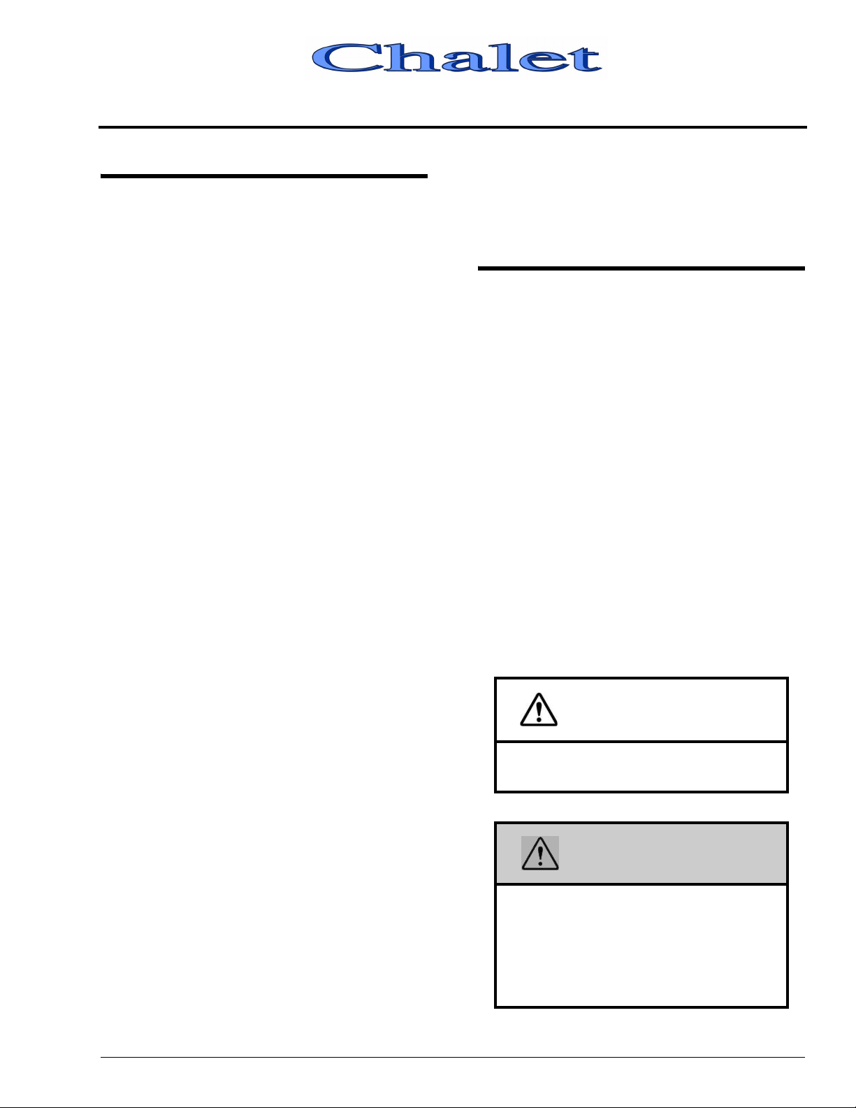
SECTION 4 – ROADSIDE EMERGENCY
IF YOU GET A FLAT TIRE
When you experience a tire failure, it creates a
side force that pulls the vehicle in the direction of
the failed tire. Unfortunately, many people make
the situation worse by slamming on the brakes
and swerving into another traffic lane. You can
control the vehicle with smooth, deliberate
maneuvers.
• DO NOT panic.
• DO NOT stomp on the brake. This abruptly
shifts the vehicle’s weight forward, making it
nose-dive and pull toward the blown-out side.
• DO NOT jerk your foot off the accelerator.
Just ease back on the accelerator slowly and
gently to continue momentum. The deflated
tire will slow down the vehicle.
• Try to steer the vehicle as straight as possible
and avoid quick maneuvers. You may need to
counter-steer to compensate for “pull” created
by the failed tire.
• Let the vehicle coast to a stop, gently steering
to a safe stopping place. Don’t worry about
damaging the wheel rim by driving on it. A
wheel replacement is cheaper than damaging
the vehicle or injuring yourself.
read all tire changing information in the chassis
operating guide.
Never get beneath a vehicle that is held up by
a jack only.
RECOVERY TOWING
When calling a professional towing service,
we recommend that you advise them of your
coach length and approximate front axle weight.
This will allow the towing operator to determine
the proper towing equipment to use. (This
information is found on the vehicle certification
label located to the left of the steering wheel.)
We recommend that you ask for an underlift
(wheel lift or frame lift) type towing assembly for
safe towing.
Winnebago Industries does not assume
responsibility for damage incurred while towing
this vehicle.
NOTE:Consult the chassis operating guide for
any additional towing instructions or
precautions provided by the chassis
manufacturer.
• Activate your hazard flashers to warn other
motorists, then exit the vehicle carefully.
• Set out flares or other warning devices.
Check your tires for proper inflation before
each trip and at least once a month with an
accurate tire gauge.
Emergency Road Service
Because of the size and weight of this vehicle
and its tires, and the possible complications
involved in tire changing, we strongly advise
obtaining professional road service to change a
flat tire whenever possible. However, if an
emergency requires you to change the tire
yourself, please exercise extreme caution and
CAUTION
Do not lift on bumper. Damage will result
to front end body parts.
WARNING
Stay out from beneath the motor home
while it is suspended by the towing
assembly unless the vehicle is
adequately supported by safety stands.
Do not allow passengers to occupy a
towed vehicle.
5 - DASH / AUTO
4-1
SECTION 4
– Roadside Emergency
JUMP STARTING
If your coach will not start from the
automotive batteries, try using the aux. start
switch to divert power from the coach batteries to
the start. (See Aux. Start Switch in Section 5). If
you wish to try jump starting the engine using
another vehicle or booster system, see your
chassis owner’s manual for connecting jumper
cables to the automotive electrical system.
WARNING
Do not attempt to push-start this vehicle.
Damage to the transmission or other
parts of the vehicle will occur.
Class A
Do not attempt to start the vehicle by hotwiring.
ENGINE OVERHEAT
If you see or hear steam escaping from the
engine compartment or have any other reason to
suspect an extreme engine overheating condition,
pull the vehicle over to the roadside as soon as it
is safe to do so, stop the engine and get all
passengers out of the vehicle.
WARNING
Operating a vehicle under a severe
overheating condition can result in
damage to the vehicle and may result in
personal injury.
For information on what to do in case of
overheating, consult your chassis operating
guide.
4-2
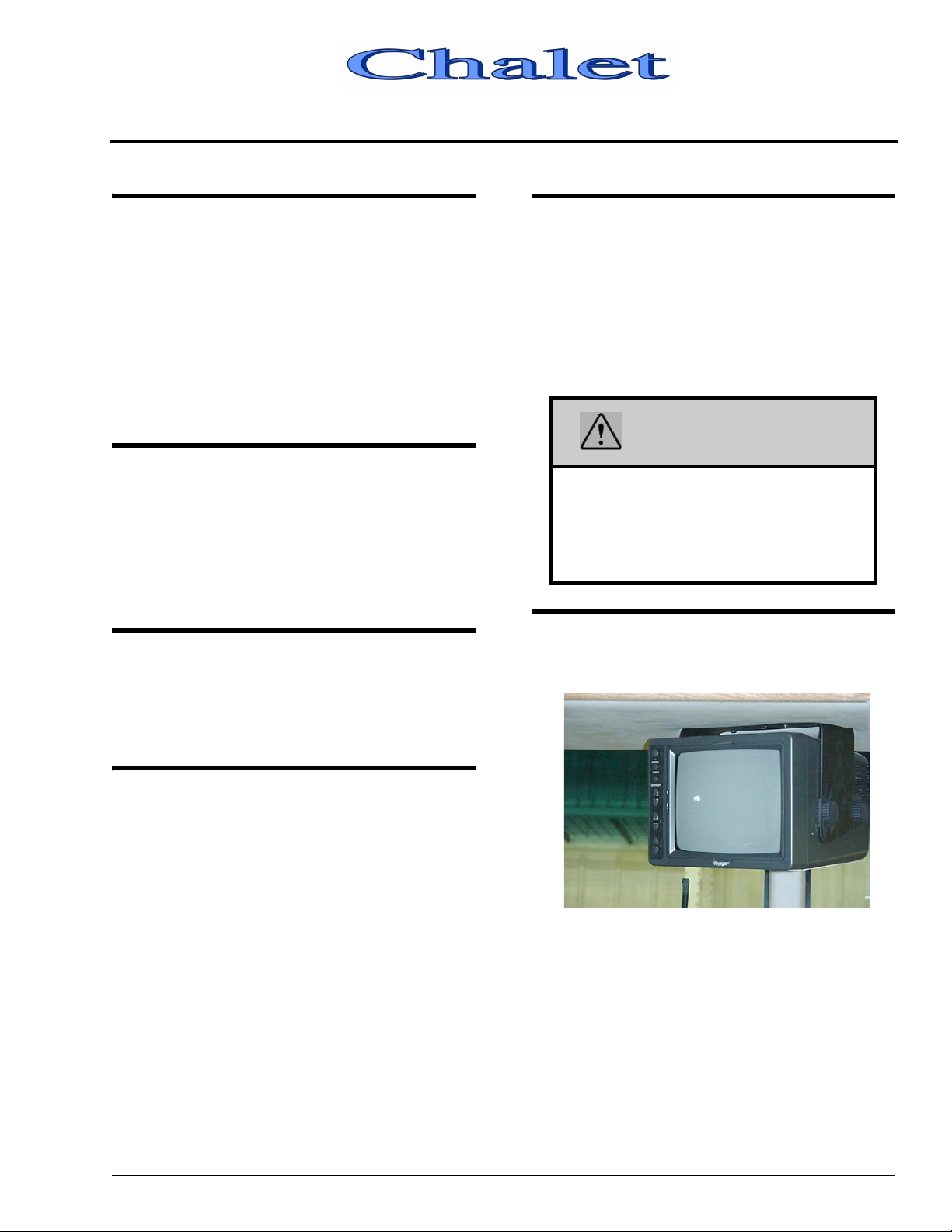
SECTION 5 – DASH / AUTO
INSTRUMENT PANEL GAUGES AND CONTROLS
The information on the following pages
describes features installed or adapted to the dash
and driver’s area by Winnebago Industries.
See your chassis operating guide for detailed
information on the instrument gauges, steering
column controls, brakes, and other chassis
original equipment.
HEADLIGHT BEAM CHANGE AND TURN SIGNALS
Move multi-function lever upward for right
turn signal and downward for left turn signal.
Pull end of handle toward you to switch high
beam to low, or low beam to high.
WINDSHIELD WIPERS AND WIPER DELAY
CRUISE CONTROL
The electronic speed control (cruise) allows
you to maintain a steady speed and relieve
driving strain while traveling long distances.
See your chassis operator guide for complete
instructions and precautions on the cruise
control.
WARNING
Do not operate the cruise control on icy or
extremely wet roads, winding roads, in
heavy traffic, or in any other traffic
situation where a constant speed cannot
be maintained.
REARVIEW MONITOR SYSTEM
–Optional
See your chassis operating guide for complete
operating information.
HAZARD WARNING FLASHER
The hazard warning flasher provides
additional safety when the vehicle must be
stopped on the side of the roadway and presents a
possible hazard to other motorists. When the
flasher is on, it serves as a warning to the other
drivers to approach and overtake your vehicle
with caution.
The front directional signals and the taillights
will flash intermittently when the flashers are in
operation. The hazard warning flashers will not
operate when the service brake pedal is
depressed. The turn signal will not operate when
the flashers are on. When it is necessary to leave
the vehicle, the flasher system will continue to
operate with the ignition key removed.
5 - DASH / AUTO
If your motor home is equipped with this
optional system, refer to the Owner InfoCase for
specific instructions provided by manufacturer.
5-1
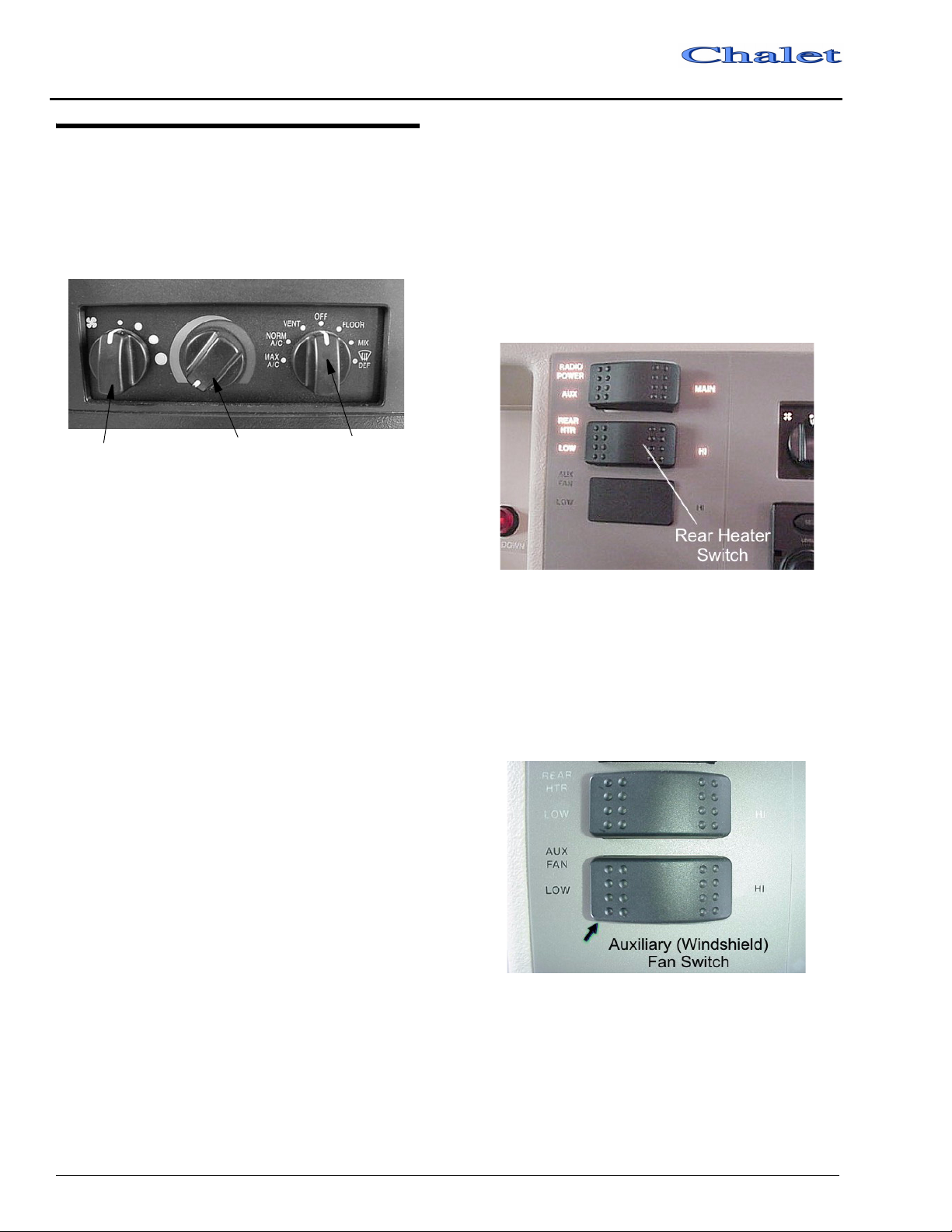
SECTION 5
– Dash / Auto
COMFORT CONTROLS
Controls for the air conditioner, heater,
defroster and vent are all combined into one
control panel. Refer to the following instructions
for use of individual controls.
Class A
and small amount to floor vents.
Off - When no heating, cooling or ventilation are
not required; closes all air dampers and turns
fan off.
Rear Auto Heater
To provide auxiliary heat to the rear of the
vehicle, turn the rear heater fan switch to the
desired speed. The switch has three positions: Hi,
Low and the middle position is Off.
Fan Switch
Temp Control Mode Selector
Fan Switch
Smallest dot is lowest air movement; Largest
dot is maximum air movement. Fan will run at set
speed when mode knob is in any position except
Off. When mode knob is set to Off, the fan will
not run.
Temp Control
Blue = Cold / Red = Warm
Mode Selector Positions
Max A/C - Cab air is recirculated (and re-cooled)
through air conditioner.
Norm A/C - Directs outside air through air
conditioner cooling fins to reduce cab
temperature.
NOTE:The dash air conditioner is not designed
to cool the entire interior of the coach,
but is intended to cool the cab area only.
Vent - Directs outside air through dash vents.
Incoming air temperature can be adjusted
using temp control knob, although cooling is
limited to a few degrees above ambient
outside air temperature.
Floor - Directs most air to floor vents and small
amount to windshield defrost vents.
Mix - Splits air between floor and windshield
defrost vents.
Def - Directs most air to windshield defrost vents
Aux Fan Switch
The two-speed auxiliary fans are intended to
assist the automotive windshield defroster
system in clearing fog and frost in cold weather
or humid conditions. The middle position on the
switch is OFF.
5-2

Class A
AUX. START SWITCH
This switch can be used to provide emergency
starting power from the motor home auxiliary
battery if the automotive battery is dead.
Aux. Start Switch
If engine battery is dead, press and hold while
turning ignition key for emergency starting
power.
SECTION 5
– Dash / Auto
Radio Power Switch
The radio power switch lets you connect the
dash radio to the coach batteries with the ignition
switch turned off for listening while parked. This
prevents accidental draining of the chassis
(starting) battery with prolonged use of the radio.
IN-DASH RV RADIO
The RV RadioTM in your coach can receive
AM/FM stereo and Weather band stations. It also
has both cassette and compact disc (CD) players
for your listening enjoyment through quality
high-output speakers located in several areas of
the coach.
TM
Please refer to the RV Radio
manufacturer’s operating guide in your Owner
InfoCase for detailed instructions on
programming preset station buttons and using
this full-featured radio/audio system.
CB RADIO WIRING
Your coach is pre-wired for CB radio
installation. The wires are located beneath the
dash to the left of the steering wheel.
Look for a pair of wires, yellow (+) and white
(-), with connectors and flag labels, suspended
from the wiring harness.
Be sure to read the wire labels before
installing a CB radio. The labels contain
important information and cautions.
CB Wires
(in plastic sheath)
5 – Dash / Auto
5-3

SECTION 5
– Dash / Auto
SWR Adjustment - If equipped
w/Antenna
To adjust CB antenna SWR (standing wave
ratio), turn the adjusting ring of the antenna to
achieve the lowest SWR reading. This procedure
will help optimize transmitting and receiving
capabilities of the radio system.
Class A
Jacks Down Light
The “Jacks Down” reminder is intended to
warn you to retract your leveling jacks before
moving the vehicle. The light will come on
briefly and a chime will sound when the ignition
key is turned to the On or Run positions if the
jacks are down.
COACH LEVELING SYSTEMS
The coach leveling system performs the dual
function of leveling and stabilizing the vehicle.
When leveling the vehicle, it may not be
necessary to use all of the leveling jacks;
however, to stabilize the vehicle, all jacks should
be extended to contact the ground.
NOTE:To prevent improper operation of the
leveling system - which could result in
damage to the levelers and/or the vehicle
itself, read the operating instructions
carefully before using the leveling jacks.
The leveling system manual is in your
Owner InfoCase.
5-4

Class A
WARNING
• Do not use the coach leveling system
as a lift for changing tires or working
under the vehicle.
• Never check for hydraulic fluid leaks
using your hands and/or any other
body part. The leaking fluid is under
pressure and is capable of cutting and
penetrating your skin, resulting in
severe injury.
• When extending the rear stabilizers,
do not lift the wheels beyond ground
contact. This makes it possible for the
vehicle to roll unexpectedly forward
(or backward) off the jacks. This could
cause severe injury or death.
• Holding a control switch in the
“extend” or “retract” position for a time
period longer than necessary to fully
extend or retract the hydraulic
cylinders, can cause overheating and
damage to the pump motor as well as
the electrical components.
• Do not use the leveler as an
emergency brake. They are not
designed for any type of vehicle
braking purpose.
• Do not use the levelers on icy or slick
surfaces on which the foot pads may
slip.
IN THE EVENT OF ACCIDENTAL
EXTENSION.
SECTION 5
– Dash / Auto
1. Bring the vehicle to a safe and complete stop as soon as possible.
2. Turn the leveling systems power switch on and press the all up switch.
3. Visually inspect the vehicle undercarriage for any problems.
5 – Dash / Auto
5-5


SECTION 6 – APPLIANCES AND EQUIPMENT
NOTE: Some items described in this section may
be optional and, therefore, may not be in
your vehicle.
The appliances installed in your motor home
are manufactured by reputable RV appliance
makers and have been tested by independent
laboratories to meet all applicable standards and
codes set for RV appliances. These appliances
are covered by your New Vehicle Limited
Warranty. (Certain items may be covered by
individual manufacturer’s warranty.) See your
New Vehicle Limited Warranty for details.
REFRIGERATOR
The refrigerator in your coach can be operated
from either of two power sources available to the
motor home:
• 110-Volt AC electric
• LP gas
Leveling
Before operating the refrigerator when the
motor home is stationary, place a small level on
the freezer plate and make certain the unit is
level.
Normal vehicle leveling to provide comfort
for the occupants is satisfactory for refrigerator
operation. This will be well within the operation
limits of 3° off-level side-to-side and 6°off-level
front-to-back.
Operating Instructions
The refrigerator is an absorption type which
uses an ammonia-water solution for cooling.
Basically, ammonia vapor is distilled from the
solution by heat, produced from either LP gas or
electricity, and then carried to the finned
condenser where it liquefies. The liquid then
flows to an evaporator where it creates cold
temperatures through evaporation.
CAUTION
To prevent permanent damage to the
refrigerator cooling unit, turn the
refrigerator off if the vehicle will be parked
on an incline of over 3° side-to-side or 6°
front-to-rear (such as steep driveways or
parking lots, etc.) for more than one hour.
Models with Electronic Auto Mode Control
5 - DASH / AUTO
Start-Up Instructions - Gas Mode
The control panel is located between the
freezer compartment and fresh food
compartment. It contains mode and temperature
switches and LED indicators. The On and Gas
indicators illuminate to indicate the refrigerator’s
operating mode.
6-1

SECTION 6
– Appliances and Equipment
The above switch turns the refrigerator On or
OFf. If the switch is slid to AUTO, it will turn the
refrigerator On and run in automatic mode.
The temperature selector switch controls the
refrigerator and freezer temperature during both
gas and electric operation. Slide the switch to
select the desired temperature setting.
When set to AUTO mode, the refrigerator will
automatically use 110-volt power if the shoreline
is plugged in or generator running. If 110-volt
power is not available, the refrigerator will
automatically switch to run on LP gas.
NOTE: The power cord must be plugged into the
generator receptacle for generator
operation.
If an operating mode is not functional, its
corresponding indicator will flash and the
refrigerator will attempt to operate in a lower
power priority source. If a lower power priority
source is not available, the indicator will continue
to flash, and the refrigerator will cease operation
Class A
until the energy source is corrected. Refer to the
“Diagnostic” section of the “Norcold
Refrigerator Operator’s Guide” in your InfoCase.
Auto and Manual Modes - Gas
Operation Only
If the gas does not ignite within 30 seconds,
which may occur on initial start-up, the
refrigerator’s gas valve will automatically close
and the operating controls will select an alternate
power source (AUTO Mode) or revert to a standby mode in which the GAS indicator flashes. The
indicator continues to flash until the refrigerator
is turned OFF and then ON. If the gas does not
ignite after several attempts, check the input gas
supply, or consult with your dealer or an
authorized service center.
Backup Operating System (“BOS”)
Your refrigerator features a Backup Operating
System which keeps the refrigerator cool in the
event of a failure of the refrigerator’s operating
controls. If a failure occurs, the TEMP SET LED
flashes and refrigerator switches to the BOS
mode. This mode provides refrigeration until the
refrigerator is serviced. The fresh food and
freezer compartment temperatures should be
monitored to prevent over-freezing or thawing of
refrigerator contents when operating in the BOS
mode. If the refrigerator temperature is too cold,
adjust the thermostat to the left in single LED
increments. If the refrigerator temperature is too
warm, adjust the thermostat to the right in single
LED increments. Let the refrigerator operate at
the new setting for one hour before rechecking
the freezer and fresh food compartment
temperatures. (Frequent door opening prevents
the temperatures from stabilizing.) Although the
refrigerator can operate in this mode, have
refrigerator serviced to restore manual operation
as soon as practical.
Operating Tips
• The refrigerator should already be cold before
placing items in it.
• Food and beverages should also be cold
before placing in RV refrigerator. Never put
warm or hot items in a cold refrigerator.
6-2

Class A
• Do not pack the refrigerator too full. The
refrigerator needs room for cold air to
circulate.
• Use smaller containers for each item. (e.g. a
half gallon container of milk instead of a halffull gallon jug)
• Always put foods, especially liquids, in
tightly sealed containers.
• Use crumpled paper between loose items to
reduce rattling or “clinking” noises.
SECTION 6
– Appliances and Equipment
Refrigerator Access Door Latches
To Close:
Further Information
For further information and operating
cautions, see the refrigerator operating
instructions.
REFRIGERATOR SERVICE ACCESS COMPARTMENT
(Exterior)
The exterior refrigerator compartment allows
access to the rear of the refrigerator for
inspection, maintenance and service.
To Open:
1. Use a screwdriver or coin to turn the latch
knobs to the vertical position as shown.
2. Remove the door from the opening.
1. Replace the door into the opening.
2. Push the latch knobs in while turning to the horizontal position as shown.
RANGE AND OVEN
The range and oven in your motor home are
operated on LP gas and will provide nearly all of
the functions that the range in your home does.
The range has a “Pilot Off” position on the oven
control which allows the oven pilot to be turned
off when traveling or refilling the LP tank.
The following warning label has been located
in the cooking area to remind you to provide an
adequate supply of fresh air for combustion.
6 – Appliances and Equipment
6-3

SECTION 6
– Appliances and Equipment
WARNING
IT IS NOT SAFE TO USE
COOKING APPLIANCES
FOR COMFORT HEATING
Cooking appliances need fresh air for safe
operation. Before operation
1. Open overhead vent or turn on exhaust fan.
2. Open window
FAILURE TO COMPLY COULD RESULT IN
DEATH OR SERIOUS INJURY.
Class A
Unlike large homes, the oxygen supply inside
a recreational vehicle is limited due to its size. To
avoid danger of asphyxiation, provide proper
ventilation when using the gas rangetop or gas
oven. It is especially important not to use the gas
oven and range top for comfort heating. Danger
of asphyxiation is greater when these appliances
are used for long periods of time.
WARNING
Portable fuel-burning equipment
including wood and charcoal grills and
stoves, should not be used inside the
recreational vehicle. The use of this
equipment inside the recreational vehicle
may cause fires or asphyxiation.
Lighting Range Top Burners
1. Rotate the Top Burner IGNITOR knob
clockwise (in direction of ‘Lite’ arrows) to
provide ignition spark at burners.
3. When the burner lights, release the Ignitor knob and turn the Burner Knob to the desired flame height.
WARNING
Do not turn burner control knob to “On”
and allow gas to escape before turning
ignitor knob.
Lighting Oven Pilot
2. While rotating the IGNITOR knob, turn the desired Burner Knob to the LITE position.
6-4
NOTE:If range has not been operated for a long
period of time, a longer waiting period
for ignition of the pilot may be necessary
due to air in the gas line.
1. Be sure all valves are in the “OFF” Position. The oven control knob should be in “OFF” position.
2. Turn on LP tank supply valve.
3. Press and turn control knob to the “PILOT ON” position. This will allow gas to oven pilot.

Class A
located on left side of burner.)
4. Open oven door and light oven pilot with a match. Small flame will be noted at the top of the pilot burner.
SECTION 6
– Appliances and Equipment
MICROWAVE OVEN
For complete operating instructions, refer to
the manufacturer’s information provided in your
InfoCase.
RANGE HOOD
The range hood vent draws cooking odors and
airborne grease particles into the filtration grid
and recirculates the air or vents it to the outside of
the coach depending on model. A light on the
underside of the hood provides better
illumination for food preparation. See the
manufacturer’s information for instructions on
replacement of light bulbs and grease filter
elements.
6 – Appliances and Equipment
Lighting oven pilot (when pilot is
Operating Oven Control
Push in and turn the oven control knob
(counterclockwise) to the desired temperature
setting.
There is a delay of about 45 seconds before the
main burner ignites. This is normal and there is
no gas escaping during this delay. It is also
normal for the oven burner flame to cycle off and
on at all temperatures except broil (BR).
Shut Down Instructions
When you are done using the oven, turn the
knob to “Pilot On” position - not Off.
The Pilot On position will turn off the main
oven burner but leave the oven pilot burning. The
“Off” position will shut down the pilot light so
you would have to relight it before using the oven
again.
Turn the knob to the Off position and close the
main LP tank supply valve to shut the pilot light
down while the vehicle is in motion and during
storage periods.
Hood Fan and Light Switches
To turn on the range hood light, simply press
the switch labeled “Hood Light”. To operate the
range hood fan, press the “Hood Fan” switch.
6-5

SECTION 6
– Appliances and Equipment
SYSTEMS MONITOR PANEL
(Wall Mounted)
Class A
actually be some fluid left in the tank. However,
when the indicator reads FULL, the tank is
actually full.
Tank Capacities
See “Capacities” page (1-1) at the front of this
manual.
The System Monitor Panel provides a
convenient central location for checking the
condition of all utility systems in your coach. At
the touch of a button this panel can display the
fresh water and holding tank levels, LP gas tank
level, plus the coach battery condition. You can
start the auxiliary generator or turn on the water
pump or water heater. Indicator lights tell you if
the water pump is on or if the water heater pilot
light is out.
At the push of a single button the monitor
panel simultaneously displays the coach battery
condition and levels of the water tank, holding
tanks and LP tank.
Water And Holding Tank Levels
Press and hold the “Levels Test” switch to
show approximate level on the monitor lights.
The approximate fluid levels are measured by
electronic sensors on the sides of the tanks. There
is generally more fluid in a tank than indicated on
the monitor panel.
For example, if the fluid level is 1-2” below
the FULL sensor, the monitor will show the level
to be only 2/3 even though the tank is nearly full.
If the fluid level is below the 1/3 sensor, the
monitor will register an empty tank because the
fluid is no lower than the 1/3 sensors. There may
LP Gas Level
Press and hold the “Levels Test” switch to
show approximate LP tank level.
The LP level is registered by a sending unit on
the tank. The gauge mounted on the side of the
tank will give a more accurate indication of
actual tank level if needed.
Water Pump Switch
When use of the self-contained water system
is desired, turn the “Water Pump” switch on. The
“Pump On” light will illuminate when the pump
switch is on and the system is operable. Water
will be available as soon as a faucet is opened.
Refer to “Water Pump” on page 10-1 for
additional information on the water pump and
initial start-up. (There is also a pump switch in
the water center compartment on the outside of
the coach).
6-6

Class A
SECTION 6
– Appliances and Equipment
6 – Appliances and Equipment
Battery Charge Meter
Push the “Levels Test” button to check the
level of charge (voltage) in the 12-volt coach
battery. The colored segments (red, yellow and
green) will light from the bottom up to the
amount of charge the battery contains.
• Green - good or adequate charge.
• Yellow - marginal charge.
• Red - battery needs charging before use.
To get an accurate reading;
1. Both the chassis engine and the auxiliary
generator engine must be shut off and 110 Vac
shoreline unplugged.
2. An interior light should be turned on to
provide a small load which draws off the
battery surface charge.
WATER HEATER
Direct Ignition Models
Water Heater Capacity: 6 gal.
1. Place Water Heater switch in the “On”
position. The switch and “Pilot Out” light are
located on the monitor panel.
2. If “Pilot Out” light stays on longer than 15 seconds, place switch in “Off” position and wait 5 minutes.
3. Repeat step one.
4. If heater fails to operate due to high water temperature, the heater will go into a lockout condition (“Pilot Out” light on). When water cools, reset by placing switch in “Off” position for at least 30 seconds, then return to “On” position.
5. If a lockout condition persists, contact your dealer.
6. For complete shut-down before servicing: a)Place Water Heater switch in “Off”
position.
b)Remove red wire from left-hand terminal
of ECO switch (ECO to valve).
Water Heater Switch and “Pilot Out” Indicator
Be sure the water heater is filled with water
before pressing this switch. To fill the water
heater, turn the water pump switch on and open a
hot water faucet until water begins to flow.
The “Pilot Out” light will glow for about 1015 seconds after the water heater switch is turned
on, then it will go off.
If the “Pilot Out” light comes on during
normal operation, it means that the burner has
gone into “lockout” mode. Turn the switch off for
about 5 minutes, then turn back on.
6-7

SECTION 6
Flow
Mode
– Appliances and Equipment
Class A
Pressure-Temperature Relief Valve
On occasion, water may be seen seeping from
the water heater pressure temperature relief
valve. This is no cause for repair or replacement
of the valve.
Water Heater Exterior Service Access
Normally there is an air gap at the top of the
water heater tank which acts as a pressure buffer.
In time, however, heated water may expand and
fill this air gap, causing a slight increase in water
pressure. This may cause the P-T valve to “weep”
until the air gap is manually replaced.
CAUTION
3. Pull the handle of the P-T valve straight out and allow water to flow until it stops.
Open
Lift handle straight out to open P-T valve
4. Let the handle of the P-T valve snap shut.
5. Close the faucet and turn on the water supply before switching the water heater on.
Manually operate the pressure temperature
relief valve at least once a year.
Water Heater By-Pass Valve
Your coach may be equipped with a water
heater by-pass valve for easier winterization of
water lines using RV antifreeze. See page 10-8
for valve location.
Turn the handle as shown to either by-pass or
flow through the water heater.
Operate this valve only when the water
heater and engine cooling system* are
cold!
*If your water heater is equipped with the
optional Motor Aid system, it uses an
extension from the engine cooling system to
heat water in the water heater while driving.
The engine cooling system must also be cold
before opening the pressure-temperature
relief valve. See “Motor Aid” for more
information.
To Replace the Air Gap:
1. Turn off the water heater switch and incoming water supply (city water and/or demand pump).
2. Open a faucet in the motor home to relieve water pressure.
6-8
Normal
By-Pass
CAUTION
Leave by-pass valve handle in NORMAL
FLOW position if draining water and
blowing out water lines. Place in BYPASS
position ONLY when using antifreeze
solution in water lines.

Class A
MOTOR AID
–Optional
The motor aid uses heat from the chassis
engine cooling system to heat water in the water
heater while driving. Hoses are routed from the
engine to a heat exchanger surrounding the water
heater tank.
Under normal conditions, the entire contents
of the water heater can be heated to about 140°F
in about two hours or 100 miles of driving. This
means you can have hot water at the faucets
immediately upon arriving at a site, or even while
driving if needed.
The motor aid also increases the capacity of
the engine cooling system, allowing the engine to
run cooler under many conditions.
SECTION 6
– Appliances and Equipment
6 – Appliances and Equipment
CAUTION
Any leak in the heat exchanger or its
supply or return lines could cause loss of
coolant and subsequent engine failure.
We recommend that you periodically
inspect these connecting lines and the
heater to insure that no leaks have
developed.
Motor Aid Water Heater and Rear Auxiliary Heater Maintenance
Have your authorized dealer check all hose
clamp connections on the rear automotive heater
and the motor aid water heater at least every six
months and tighten them if necessary.
6-9


SECTION 7 – HEATING AND AIR CONDITIONING
NOTE: Metal coatings used during manufacture
LP GAS FURNACE
Start Up:
1. Open the LP gas tank valve by turning fully
counterclockwise.
Further Information
provided in your Owner InfoCase for further
information, including operating precautions,
and periodic maintenance. See the Coach
Maintenance Schedule at the back of this manual
for recommended intervals.
of the furnace burner parts may smoke
when the furnace is used for the first
time, which may also set off your smoke
alarm. If this happens, provide adequate
ventilation of the smoke to avoid a
nuisance smoke alarm at this time. We do
not recommend removing the smoke
alarm battery. If it were inadvertently left
disconnected, the smoke alarm would be
inoperative.
Please see the furnace operating instructions
2. Move thermostat switch from OFF to HEAT
and press the Temp Selector button (Up/Down
arrows) until the desired temperature is shown
on the display.
3. Furnace fan will start to blow soon after
setting thermostat.
4. After about 30 seconds, the furnace burner
will light.
5. The furnace will now cycle off and on
automatically as the thermostat demands just
like a household furnace.
NOTE:If heat does not come out of the heat
ducts after a minute or so the burner is
not lit. Turn thermostat off for 3-5
minutes, check to be sure tank valve is
open and tank is not out of fuel, then try
steps 2-4 again. If it still will not light
after three attempts, go to Shut Down
steps and contact your dealer or a local
RV service center.
5 - DASH / AUTO
To Shut Down:
1. Slide thermostat switch to OFF position.
2. Close LP tank valve.
7-1

SECTION 7
– Heating and Air Conditioning
Class A
THERMOSTAT OPERATION
The following chart shows the system functions with the “Heat/Cool” thermostat. Disregard references to
heat functions when using the “Cool Only” thermostat in the rear bedroom.
7-2

Class A
HEAT PUMP
–Optional
Your coach may be equipped with an air
source heat pump built into the air conditioning
system. Because the heat pump operates on
electricity, it provides economical heat inside
your coach and helps reduce the use of LP gas for
heating in cooler weather.
A heat pump can be thought of as an air
conditioner running in reverse. An air
conditioner absorbs heat from the air on the
inside of the coach and moves it to the outside.
The heat pump does exactly the opposite. Even
cold air contains some heat, so a heat pump will
extract heat from the outside air on a cold day and
carry it to the inside of the coach to maintain a
comfortable temperature.
The efficiency of a heat pump decreases as the
outdoor air temperature drops, so supplementary
heat is often needed when the outside
temperature nears freezing. This system is set to
automatically start the LP gas furnace to assist
the heat pump if room temperature cools to 5
degrees or more below the thermostat set
temperature. You may wish to manually switch
to furnace heat to maintain a higher temperature
when outside temperatures begin to reduce the
efficiency of the heat pump. The heat pump will
not operate when the outside temperature falls
below 36 degrees F.
To Operate the Heat Pump:
• Slide the Thermostat switch to Electric heat
mode.
• If the inside temperature is 5 degrees or more
below the thermostat set point, both the heat
pump and the furnace will run initially to
bring the interior temperature up to the set
point as quickly as possible. (If the inside
temperature is 4 degrees or less below the set
point, then only the heat pump will run
initially.)
• When the thermostat is satisfied, the heat
pump and furnace will both shut off.
SECTION 7
– Heating and Air Conditioning
• When the thermostat calls for heat again, only
the heat pump will run. The heat pump will
remain the sole heat source unless it cannot
maintain the inside temperature. If the inside
temperature falls five degrees below the set
point, the furnace will assist the heat pump
until the set point is reached.
If the furnace must assist the heat pump three
times in a row, the thermostat will shut down the
heat pump for two hours and the furnace will take
over as the heat source. After two hours the heat
pump will become active again and try to be the
primary heat source.
7 – Heating and Air Conditioning
Gas Heat = Gas Furnace
Electric Heat = Heat Pump
Cool = Roof Air Conditioner
Have You Checked Your Air Filter Lately?
Closed or blocked vents and a dirty air filter
can hinder the efficiency of a heat pump.
• Be sure ceiling vents are open to distribute
heat pump output air.
• The washable foam filter should be checked
monthly for dirt build-up and cleaned or
replaced as needed. It is located in the ceiling
mounted return AC grille in the lounge area.
DUCTED ROOF AIR CONDITIONING SYSTEM
The furnace thermostat also controls ducted
roof air conditioner operation when the
thermostat switch is placed in position.
7-3

SECTION 7
– Heating and Air Conditioning
Class A
NOTE:The thermostat is equipped with a
replaceable 2 Amp fuse located on the
back of the thermostat body.
Refer to the manufacturer’s information in
your Owner InfoCase for complete operating
instructions.
NOTE:The ducted roof air conditioning system
has ceiling registers that can be closed if
necessary to force more cool air toward
a specific area of the coach or to route
cool air away from a specific area. If too
many vents are closed, however, it can
cause the air conditioner unit to shut
down, particularly in high humidity
conditions.
All cooling functions controlling to setpoint
have a short cycle protection time delay of 3
minutes. There will be no delay if the cycle OFF
time exceeds 3 minutes.
Rear Air Conditioner Power Selector Switch
The rear air conditioner will not operate if the
switch is not in the proper position for the power
source being used.
(models with 2 roof air units only)
If you want to run the rear AC unit, you must
switch the Rear A/C Selector switch to the proper
power source.
• If you are using the shoreline, the switch must
be in POWERCORD position.
• If you are using the generator, the switch must
be in GENERATOR position.
7-4

SECTION 8 – LP GAS SYSTEM
LP GAS SUPPLY
The LP gas system supplies fuel for the range,
water heater, furnace and refrigerator (while in
gas mode). When used and handled properly, this
system is safe and economical and provides
modern living conveniences wherever you travel.
How LP Gas Works
LP (Liquified Petroleum) gas is a true gas
compressed into liquid form for easy
transportation and storage. LP gas is available in
two types - propane and butane. It is also called
tank gas, bottle gas, or simply LP.
LP is used by appliances in vapor form only,
but is stored in the tank as a liquid under very
high pressure. As the liquid gas is released, it
reverts back to a vapor and expands to many
times its compressed volume.
LP GAS WARNINGS AND PRECAUTIONS
• All pilot lights must be extinguished and
appliances turned off while refilling the fuel
tank or LP tank.
LP TANK SYSTEM
The storage reservoir for the LP gas system is
a horizontally mounted tank which is
permanently attached to the vehicle frame. The
tank is accessible only from the outside of the
vehicle. The tank supply valve is located near the
top center of the tank, next to the regulator.
Before opening the supply valve, check to be sure
all controls for gas appliances are in the “Off” or
“Pilot Off” position. If this step is not performed,
LP gas could accumulate inside the motor home
creating a fire or explosion hazard.
• Never smoke while refilling vehicle fuel tank
or LP gas tank.
• Avoid inhaling exhaust gases produced by
burned gasoline, diesel fuel or LP gas in items
such as the range, chassis engine, generator
engine, refrigerator, furnace and water heater.
They contain carbon monoxide, which is an
odorless, colorless and poisonous gas.
• Do not bring or store LP gas containers,
gasoline or other flammable liquids inside the
vehicle because a fire or explosion may result.
LP gas containers are equipped with safety
valves which relieve excessive pressure by
discharging gas to the atmosphere.
• Do not fill LP gas container(s) above 80
percent of capacity. Overfilling the LP gas
container can result in uncontrolled gas flow
which can cause fire or explosion. A properly
filled container will contain approximately 80
percent of its volume as liquid LP gas.
5 - DASH / AUTO
8-1

SECTION 8
– LP Gas System
• Never use an open flame to test for LP gas
leaks. Replace all protective covers and caps
on LP system after filling. Make sure valve is
closed and door latched securely.
• Never connect natural gas to the LP gas
system.
• When lighting stove burners, place the lit
match, butane wand or other ignition source
next to the burner before turning the knob
‘On’. Do not let gas escape before lighting the
match or lighter wand.
• Portable fuel-burning equipment, including
wood and charcoal grills and stoves, shall not
be used inside the recreational vehicle. The
use of this equipment inside the recreational
vehicle may cause fires or asphyxiation.
• LP gas regulators must always be installed
with the diaphragm vent facing downward.
Regulators are equipped with a protective
cover. Make sure that the regulator vent faces
downward and that the cover is kept in place
to minimize vent blockage which could result
in excessive gas pressure causing fire or
explosion.
Class A
LP GAS ALARM
Your coach is equipped with an LP gas
detector which sounds an alarm if an unsafe
amount of LP gas is present inside the coach.
Because LP gas is heavier than air, the detector is
located on a cabinet face near the floor of the
coach.
See the LP Gas Alarm manufacturer’s
information in your InfoCase for complete
instructions.
LP Gas Alarm
LP GAS LEAKS
The following label is located in the vehicle
near the range area. If you smell gas within the
vehicle, quickly and carefully perform the
procedures listed.
DANGER
IF YOU SMELL GAS
1. EXTINGUISH ANY OPEN FLAME, PILOT LIGHTS AND ALL SMOKING MATERIALS.
2. DO NOT TOUCH ELECTRICAL SWITCHES.
3. SHUT OFF THE GAS SUPPLY AT THE TANK VALVE(S) OR GAS SUPPLY CONNECTIONS.
4. OPEN DOORS AND OTHER VENTILATING OPENINGS.
5. LEAVE THE AREA UNTIL ODOR CLEARS.
6. HAVE THE GAS SYSTEM CHECKED AND LEAKAGE SOURCE CORRECTED BEFORE USING AGAIN.
FAILURE TO COMPLY COULD RESULT IN
EXPLOSION RESULTING IN DEATH OR
SERIOUS INJURY.
If the Alarm Sounds
If the alarm sounds, do not touch any
electrical switches. Immediately turn off the
main LP tank valve and all LP appliances, open
all windows and roof vents, and leave the coach
until the alarm stops sounding.
If the alarm keeps sounding at regular
intervals, a leak may be present. Contact your
dealer or an LP gas service center to have the
problem corrected before using the LP system
again.
8-2

Class A
WARNING
Never use an open flame to test for gas
leaks. When testing for gas line leaks with
a soapy water solution, DO NOT use a
detergent containing ammonia or
chlorine. These substances may
generate a chemical reaction causing
corrosion to gas lines, resulting in
dangerous leak conditions.
Power Connection
The LP gas alarm is powered by the coach
batteries. If the auxiliary battery switch is shut off
or the battery cable is disconnected from the
batteries, the alarm will not work. The LP gas
alarm circuit breaker or fuse is located on the 12volt house electrical load center (breaker panel).
Because the LP gas alarm is connected
directly to the auxiliary battery, it is always
drawing a small amount of current. Even though
this current draw is slight, it could drain the coach
battery during storage periods when the house
battery will not be charged regularly by the
engine or shoreline. Turn the Aux. Batt switch
OFF to avoid current drain during storage
periods.
Other Combustible Fumes or Vapors
This alarm is designed to detect the presence
of LP gas, however there are other combustible
fumes or vapors which may be detected by the
sensor. These include: alcohol, liquor,
deodorants, colognes, perfumes, wine, adhesives,
lacquer, kerosene, gasoline, glues, most all
cleaning agents and the propellants of aerosol
cans. Most are lighter than air in their vapor state
and will only be detected when the area is closed
up. Glues and adhesives may exhaust
hydrocarbon vapors for months after they are
applied. They are easily activated by high
temperatures. If you close up an RV coach on a
hot day, the chemicals used in its construction
may be detected for several months after the
coach was manufactured.
SECTION 8
– LP Gas System
Further Information
See the manufacturer’s information entitled
“Your LP Gas Detector” in the Owner InfoCase
for further instructions on nuisance alarms and
care and testing of the LP gas detector.
SAFE USE OF THE LP GAS SYSTEM
The LP system is designed and built with strict
adherence to federal, state and recreational
vehicle industry requirements for mobile LP gas
equipment.
For your safety, there are many safety devices
and backup systems installed, such as tank fill
overflow valves, an interior LP gas detector/
alarm, and an interior carbon monoxide (CO)
detector/alarm.
LP gas also contains an odor additive that you
can smell if LP is present in the air.
Listed below are a few precautions to observe
that will help you to use the LP gas system safely.
• Exercise caution at all times. Be familiar with
the distinctive odor of LP gas. If a leak is
suspected, turn off the supply valve
immediately. Have the LP gas system checked
by your dealer or other qualified LP gas
service center.
• Do not tamper with the LP gas piping system,
pressure regulator or gas appliances. Service
and maintenance of LP gas system
components should be performed only by
your dealer or a qualified LP gas service
center.
• Never attempt to connect natural gas to the LP
gas system.
• Have the entire LP gas system inspected for
possible leaks and missing or damaged parts
at each tank filling. Also inspect before and
after each trip, and any time trouble is
suspected.
• Turn the LP supply valve off when not using
the LP gas system.
8 – LP Gas System
8-3

SECTION 8
– LP Gas System
• Never use a wrench to tighten the tank supply
valve. It is designed to close leak-tight by
hand. If a wrench is required to completely
close the valve, it is defective and must be
replaced.
• Be sure appliance and outside vents are open
and free from obstruction when using the LP
gas system.
• Never attach a lock or any device requiring a
key to the LP tank compartment door.
According to standards set for recreation
vehicles, the LP supply valve must be readily
accessible in an emergency.
• Exercise caution when drilling holes or
attaching objects to the walls. Gas lines and
electrical wiring could be seriously damaged
and present an extreme safety hazard.
Class A
REFILLING LP TANK
There are many LP gas refueling stations
located throughout the country. These stations
are listed in the telephone directory Yellow Pages
under “Gas - Liquified Petroleum - Bottled and
Bulk.”
Since the LP tank is permanently mounted to
the frame, the motor home must be taken to an LP
dealership for filling. Do not attempt to remove
the LP tank from the vehicle. The tank is
equipped with a fill adapter with both internal
and external threads which allows easy filling
with any LP filling equipment. The tank is full
when liquid LP gas appears at the overflow
valve.
NOTE:The LP tank is equipped with an
automatic 80% stop-fill device.
SELECTING LP FUEL TYPES
We recommend using straight propane in your
LP tank. Propane gas is commonly available at
all LP gas outlets in the U.S. (According to the
National LP Gas Association, LP gas outlets in
the United States do not offer any other type of
liquefied petroleum gas than propane to the
general public.) Check local phone directory
yellow pages for locations of local LP gas
refilling stations or bulk dealerships.
NOTE:If you travel outside the U.S. with your
motor home, you may find butane or
propane/butane mixtures available in
addition to propane. Because gasburning RV appliances are designed to
run on propane only, we recommend that
you request straight propane only.
Butane burns about 30 percent hotter
than propane and can overheat some
appliances, particularly refrigerators,
and cause permanent damage. Other
appliances designed to operate on
propane can become sooted and lose
efficiency by using butane fuel.
WARNING
Make sure the filling attendant uses the
80% overflow valve when filling the tank.
A tank should never be filled above 80%
level to allow for vaporization and liquid
expansion.
Do not place LP gas containers inside the
vehicle. LP gas containers are equipped
with safety devices which relieve
excessive pressure by discharging gas to
the atmosphere.
Do not place LP gas containers, gasoline,
or other flammable liquids inside the
vehicle. Fire or explosion may result.
Do not alter or remove LP tank gauge at
any time.
8-4

Class A
SECTION 8
– LP Gas System
TRAVEL WITH LP GAS
WARNING
DO NOT FILL CONTAINER TO MORE
THAN 80 PERCENT OF CAPACITY.
Make sure the motor home is level when
filling. It is possible to accidentally overfill
the tank if the vehicle is unlevel, with the
fill valve on the uphill side. Overfilling the
LP gas tank can result in uncontrolled gas
flow, which can cause fire or explosion. A
properly filled container will contain
approximately 80 percent of its volume as
liquid LP gas.
All pilot lights must be extinguished
and supply valve closed before refilling
LP gas tanks or vehicle fuel tanks.
Do not smoke or expose an open flame
while near an LP refueling area. LP gas is
heavier-than-air and extremely
flammable.
It is illegal for vehicles equipped with LP
tanks to travel on certain roadways or through
certain tunnels in the U.S. To avoid
inconvenience, check state regulations
concerning flammable gas transportation.
PRESSURE REGULATOR
The pressure regulator is protected from the
elements by a plastic cover which should be left
in place at all times. Only your dealer or a
qualified LP gas service should remove the
regulator cover for adjustments.
WARNING
Visually inspect the pressure regulator
vent periodically for blockage by
accumulated debris or insect nests, etc.
Never use an open flame to test for LP
gas leaks.
Replace all protective covers and caps on
LP system before filling.
Never fill the LP tank with engine or
generator running.
AIR IN THE LP GAS TANK
If your LP gas appliances do not stay lit or
require frequent adjustment, even though you
know the LP tank contains sufficient fuel, the
problem may be air in the LP gas tank. Air in the
tank mixes with the LP gas vapors causing them
to burn poorly. This condition could linger for
weeks if the air is not purged from the tank. Most
LP gas dealers have equipment for purging air
from LP gas tanks and will purge before refilling
the tank.
Vent obstruction could result in excessive
pressure which could cause a fire or
explosion.
8 – LP Gas System
If any obstruction is apparent, have the
regulator serviced by your dealer or a
qualified LP gas service center.
8-5

SECTION 8
– LP Gas System
Class A
If moisture begins to cause problems, have
your LP gas dealer inject a small amount of dry
methyl alcohol in your tank (approximately one
ounce to 20 pounds or one pint to 100 gallons) to
help guard against regulator freeze-ups.
In very cold weather when a large volume of
gas is being used for heating, it is possible to
experience a loss of gas pressure. At first, this
problem may appear to be caused by a regulator
freeze-up, but is actually caused by failure of the
liquid gas to vaporize as fast as it is needed. As
the temperature becomes colder, it is increasingly
harder for the liquid LP gas to vaporize. At the
same time, the demand for LP to produce heat
increases to the point where the system cannot
maintain production.
The only solution to this problem is to reduce
the consumption of gas where possible.
Adjusting the temperature on the gas/electric
refrigerator may be a first step. Using less hot
water will help as well.
Regulator freeze-ups are caused by the
presence of moisture in fuel. This moisture will
pass through the cylinder valve and into the
regulator where it can freeze. Fuel producers,
tank and bottle manufacturers and LP gas dealers
take every precaution to reduce moisture, but
sometimes only a fraction of an ounce entering
the tank can cause problems. To help avoid the
possibility of freeze-up, always keep tank control
valve closed when not in use, even when tank is
empty, to prevent moisture from collecting on the
inside.
If regulator freeze-up should occur, you may
attempt to thaw the regulator using a light bulb.
DO NOT USE AN OPEN FLAME OR HEAT
LAMP.
8-6

SECTION 9 – ELECTRICAL SYSTEMS
Your coach is equipped with an electrical
system consisting of two separate voltages; a 12volt DC system and a 110-volt AC system. The
12-volt system consists of two internal power
sources, while the 110-volt system is operated
from an outside power source or the optional
110-volt generator. All systems operate through a
single power converter control center to provide
electrical power to the motor home.
ELECTRICAL CAUTIONS
• •Careless handling of electrical components
can be fatal. Never touch or use electrical
components or appliances while feet are bare,
while hands are wet, or while standing in
water or on wet ground.
• Improper grounding of the vehicle can cause
personal injury. Do not plug the utility power
cord into an outlet which is not grounded and
do not adapt the plug to connect to a receptacle
for which it is not designed.
• Do not attach an extension cord to the utility
power cord.
• Be sure that all electrical appliances to be used
contain 3-prong plugs for proper grounding.
• Avoid overloading electrical circuits. Replace
fuses or circuit breakers with those of the
same size and amperage rating only. Never
use a higher rated fuse or breaker.
• Use caution when handling or working near
electrical storage batteries. Always remove
jewelry and wear protective clothing and eye
covering. Avoid creating sparks.
110-VOLT AC SYSTEM
The 110-volt system operates from the
shoreline cord connected to an outside 110-volt
utility service such as those at campgrounds, or
from the 110-volt generator. When the shoreline
cord is connected to an outside power source, or
when the generator is in operation, the power
converter automatically changes a portion of the
110-volt current to 12-volt DC current. All
equipment in the motor home that is normally
powered by the auxiliary batteries is then
powered through the converter.
In addition, the following equipment is
entirely dependent on 110-volt current: roof air
conditioner, refrigerator (when placed in AC
mode), microwave oven, and any 110-volt
electrical equipment used at convenience outlets.
EXTERNAL POWER CORD
(Shoreline)
The external utility power cord (commonly
referred to as a “shoreline”) is stored in the utility
compartment on the left (driver’s) side of the
coach.
WARNING
Do not connect the external power cord
to any receptacle until you have
contacted the owner and/or attendant of
the premises to verify proper polarity and
grounding.
It is the responsibility of the owner of the
electrical receptacle to ensure that the
receptacle is properly wired and
grounded.
Reverse polarity and improper grounding
of the vehicle can cause personal injury or
death.
Connecting the Power Cord
To connect to an external power source,
remove the cord from the storage compartment
and plug it into a suitable power receptacle.
An access hatch in the compartment floor lets
you route the shoreline cord out the bottom of the
compartment so you can shut the compartment
door while the shoreline is connected.
5 - DASH / AUTO
9-1

SECTION 9
30 Amp Receptacle
– Electrical Systems
Class A
WARNING
Do not plug the power cord into an outlet
which is not grounded, or adapt the plug
to connect to a receptacle for which it is
not designed.
Be sure that all three prongs of the supply
cord are properly plugged into the
receptacle.
Do not connect the power cord to an
extension cord.
Most campgrounds are equipped with a fuse
or circuit breaker at the receptacle. This protects
the park’s wiring, as well as the power cord on
your vehicle, from electrical damage. If electrical
power fails, contact the park attendants and have
them check the fuse or breaker for your supply
receptacle.
After disconnecting the power cord, neatly
replace it in the storage compartment.
The three-prong power cord is designed to
ground the electrical system through the
receptacle. It is also designed to carry the
amperage output of most campground outlets. If
the electrical receptacle to be used is designed to
mate with the three prongs on the power cord
plug, the electrical connection can be expected to
carry rated load. (See approximate power
consumption table on page 9-6.)
POWER CENTER
(Converter)
The power center changes 110-volt AC
current from the auxiliary generator or the
shoreline into 12-volt DC current for use by 12volt equipment in the motor home.
Certain circuits, however, remain unchanged
for use by items which require 110-volt current,
such as the air conditioner(s), the refrigerator in
AC mode, the microwave oven, etc.
Current drawn from the coach batteries passes
through the power center unchanged, although it
is routed through a series of protective fuses
located on the power panel.
The converter is located in a lower cabinet
face in the galley, living area, or beneath a bed.
The converter power panel contains the coach
electrical system 110-volt circuit breakers and
12-volt fuses.
9-2

Class A
12-Volt H
110-Volt Ci
SECTION 9
– Electrical Systems
rcuit
Breakers
Power Converter
ouse
Fuses
WARNING
Do not store anything around or on top of
the converter, or in front of the cover. The
converter generates heat while operating,
and needs unrestricted air flow for proper
cooling.
Charging Section
The converter charges coach batteries while
110-volt external power is connected. The
converter will automatically “sense” the
condition of the RV battery. If it is below “full
charge”, the Charging Section will start charging
the battery.
If the coach batteries have been extremely
discharged, they will accept charge at a relatively
high amperage rate. If they are only slightly
discharged, they will charge at a lower amperage
rate. The rate of charge will decrease as the
batteries reach “full charge”, then will continue
“trickle” charging at a very low amperage rate. If
your battery does not charge as described above,
it is possible the battery is defective.
Thermal Overload Protector
A protective thermal breaker will “break” the
110-volt AC power to the converter section of the
Power Center if the power converter becomes
overheated. This can result from operating above
its maximum limit for an extended period of time
or by obstruction of ventilation to unit.
NOTE:Power converter section will
automatically route 12-volt lights and
motors to battery power in this event.
The thermal breaker will reset itself after a
period of time, and the lights and motors will
again resume operation from power converter
section. If the breaker trips again shortly after
reset, take immediate steps to correct cause of
overheating. A portion of the coach 12-volt load
(lights or motors or both) should be turned off to
reduce total load. Also, inspect power converter
section to make sure ventilation is not obstructed.
NOTE:The converter will not change 12-volt DC
current to 110-volt AC.
110-VOLT CIRCUIT BREAKERS
The breaker panel protects all 110-volt
components in the motor home from either an
overload on the circuit or a short in the wiring or
component itself. When an overload or short
develops, the breaker will open preventing any
further flow of electricity and, therefore, damage
to the system.
Shut off the equipment (example: roof air
conditioner) and allow a brief cooling period.
Then reset the breaker by moving the switch to
“Off” and back to “On”. If the breaker is
continually tripped and no overload is evident,
have the system checked for a short in the wiring
or the appliances.
9 – Electrical Systems
9-3

SECTION 9
– Electrical Systems
Class A
If the GFCI keeps tripping, have the electrical
system checked and repaired if necessary before
using again.
The GFCI outlet is located in the bath,
bedroom or dinette area, depending on the floor
plan of the vehicle.
110-Volt Circuit Breakers
Further Information
Refer to the converter manufacturer’s
information provided in your Owner InfoCase for
additional information about your power
converter system.
110-VOLT RECEPTACLES
(Outlets)
A number of standard AC electrical outlets are
provided throughout the coach for connecting
small appliances such as televisions, radios,
toasters, etc. Outlets are also located on the
outside of the coach near the entrance door.
NOTE: See 12 Volt Fuse Panel in 12-Volt DC
System elsewhere in this section.
RESET
Press to
reconnect
circuit after
monthly
testing or
ground fault
tripping.
GFCI Outlet
(Ground Fault Protector)
WARNING
The GFCI will not completely eliminate
electrical shock. Small children and
persons with heart conditions or other
disabilities which make them especially
sensitive to electrical shock may still be
injured by a 110-volt receptacles even
though protected by a Ground Fault
interrupter.
TEST
Press at least
monthly.
Should break
circuit. Press
RESET
button to
reconnect.
GROUND FAULT CIRCUT INTERRUPTER
Bath, galley and exterior outlets are connected
to a GFCI (Ground Fault Circuit Interrupter),
which is an extremely sensitive circuit breaker
that will help to protect against severe electrical
shock if a ground fault develops. If such a
condition occurs, the GFCI will break the circuit
by turning off the power to the protected outlets.
Should this occur, unplug all the appliances on
that circuit and press the reset button on the GFCI
equipped outlet.
9-4
AUXILIARY 110-VOLT GENERATOR
Consult the information provided in your
Owner InfoCase for instructions on operation,
troubleshooting and maintenance.

Class A
WARNING
Careless handling of the generator and
electrical components can be fatal.
Never touch electrical leads or
appliances when your hands are wet, or
when standing in water or on wet ground.
Do not attempt to repair the generator
yourself. Service should be performed by
an authorized service center.
Do not plug the power cord into the
generator receptacle while the generator
is running.
To use the 110-volt generator, plug the power
cord into the generator receptacle within the
shoreline compartment before starting the
generator.
SECTION 9
– Electrical Systems
Basic Generator Operation
• See generator manufacturer’s operating
information for specific instructions.
• Reduce all electrical loads. (Shut off lights,
fans, appliances, etc.)
• If the generator has not been run for two
weeks or more, you may need to prime the fuel
system before attempting to start.
Generator
Receptacle
Power
Cord
Starting and Stopping the Generator
The generator switches are located on the dash
and on the monitor panel as well as on the
generator itself. The generator starter circuit does
not rely on the automotive battery, so the switch
will operate whether the ignition switch is on or
off.
This coach may be equipped with one of
several models of generators. Consult the
generator owner’s manual in your Owner
InfoCase for specific instructions on starting and
stopping your generator.
Starting:
• Press the generator starter switch on and hold
until generator engine is running, then release.
• Let the generator engine stabilize and run
smoothly before turning appliances or
electrical equipment on.
• Refer to the output specifications of your
generator in the generator manufacturer’s
manual.
• Do not overload generator by turning too
many items on. Overloading will cause the
circuit breaker on the generator to trip. If this
happens, the generator will run but no
electricity will be present in the coach. You
must then reset the circuit breaker on the side
of the generator.
Stopping:
• Before shutting generator down, turn off
electrical loads and let engine run at no-load
for a few minutes to cool down.
• Press the generator switch Off and hold until
the generator engine comes to a complete
stop.
9 – Electrical Systems
9-5

SECTION 9
– Electrical Systems
Approximate Power Requirements of
Common Appliances
Approximate Power
Appliance or Tool
Vacuum cleaner
Coffee Maker
Hair dryer
Electric clothes iron
Electric blanket
Te le v is i on
Electric drill
Air conditioner
Converter
Microwave Oven
Consumption
(Watts/Amps)
200-500W/1.7-4.3A
550-700W/4.8-6.1A
800-1500W/7.0-13.0A
500-1200W/4.3-10.4A
50-200W/0.4-1.7A
80-100W/0.7A
250-750W/2.2-6.5A
1400-2000W/13-19A
300-500W/2.6-4.3A
700-1500W/6.0-13.0A
Class A
3. Park the vehicle so that the wind will carry the exhaust away from the vehicle. Also, note the position of other vehicles to be sure their exhaust will not enter your vehicle.
4. Do not operate the generator engine while parked if vegetation, snow, buildings, vehicles, or any other object can deflect the exhaust under or into the vehicle.
Check auxiliary generator oil level frequently
during periods of use. Refer to the generator
manufacturer’s information in your Owner
InfoCase for specific recommendations.
Generator Hourmeter
This meter is located on the monitor panel. It
registers the total number of hours that the
generator has been operated. Refer to the
hourmeter to determine when periodic
maintenance is due and to record services which
have been performed.
Operation Warnings and Cautions
WARNING
The exhaust of all internal combustion
engines contains carbon monoxide (CO).
This poisonous gas is colorless, odorless,
tasteless, and lighter than air. The
exhaust systems of both your motor home
engine and your generator engine have
been installed with your safety in mind.
However, certain precautions must be
taken when using them to protect yourself
from conditions beyond the control of the
manufacturer.
WARNING
Never check generator oil level while
generator engine is running.
12-VOLT DC SYSTEM
The DC voltage system consists of the chassis
battery and the 12-volt house auxiliary batteries.
The batteries are located beneath the interior
entrance step. Release the latch and lift the top of
the step upward to remove.
1. Do not simultaneously operate the generator engine and a ventilator which could draw exhaust gases into the vehicle.
2. Do not open windows or ventilators on the end or side of the vehicle where exhaust pipe of the generator is located.
9-6
Chassis (Starting) Battery
The chassis battery is used to operate the
engine starter and automotive accessories and
controls found on the instrument panel. The
leveling jack, slideout room systems and the
electric step are also connected to the chassis
battery.

Class A
House (Aux.) Batteries
The house batteries supply current to 12-volt
equipment located in the living area of the motor
home. This includes interior lights, range exhaust
fan, furnace fan, water pump, water level and
holding tank gauges, 110-volt generator starter,
refrigerator and bath roof vent fan. The house
batteries may also be used to start the engine if
the chassis battery is dead. Refer to “Aux. Start
Switch.”
The house batteries are “deep-cycle” type
batteries specially designed for recreational
vehicle use. They will provide longer lasting
power than standard automotive batteries, and
will withstand the frequent drain-and-recharge
cycles that occur under the demanding conditions
of a camping outing.
The house batteries are automatically charged
by the engine alternator while the engine is
running.
BATTERY ACCESS
The batteries are located beneath the top
inside entrance step. Unhook the latch assembly
fastening the top step and remove.
SECTION 9
– Electrical Systems
AUXILIARY BATTERYSWITCH
(AUX. BATT)
The AUX BATT switch disconnects the
auxiliary (coach) batteries from the 12-volt
system of your coach to avoid long-term battery
drain by electrical items that are hooked directly
to the coach batteries, such as clock displays and
radio memories, etc.
Always leave this switch ON except during
storage periods. Some electronic displays and
memory functions may need to be reset after
power has been reconnected.
Release latch and lift step to access house and
chassis batteries
9 – Electrical Systems
Aux. Batt. Switch
(Near entrance door)
See also Battery Storage and Maintenance in
this Section.
9-7

SECTION 9
30
30
– Electrical Systems
DC-AC ELECTRICAL VOLTAGE INVERTER
300 Watt - Optional
The voltage inverter changes 12 volt DC
current into 110 volt AC current to operate your
TV and DVD/VCR while traveling or when
shoreline hookup is not available.
Class A
Chassis and House 12V Circuit Breakers
behind cover panel in cargo
compartment near entrance door
A label on the panel states the amperage rating
and circuit protected for each fuse or breaker.
12-Volt Fuse Panel
The fuse panel is mounted on the right-hand side
of the power converter.
• The inverter must be switched on to operate.
• Turn the inverter off when not in use to avoid
draining the coach or automotive batteries.
NOTE:Batteries will deplete quickly with use of
the inverter. The inverter is intended for
limited, short term TV/Video use while
the vehicle is in motion or while not
connected to shoreline or generator
power. It is not intended for steady use
while ‘dry camping’ without generator
or shoreline power.
12-VOLT HOUSE FUSES AND CIRCUIT BREAKERS
All 12-volt circuits and equipment in the
coach area of the motor home are protected by
either a fuse panel or breaker panel. When a
circuit is overloaded or a short develops in any
part of the system, a fuse or breaker will shut
down that circuit. If this happens, turn off all
affected lights or appliances and reset the breaker
or replace the fuse with a new one of equal
amperage rating.
110 - Volt
Circuit Breakers
Load Center
12-Volt
House Fuses
The fuse panel accepts only blade type plug-in
fuses. Always replace fuses with those of the
same amperage rating.
Good Fuse
Bad Fuse
9-8

Class A
BATTERY STOAGE AND MAINTENANCE
Lead-acid type batteries are electro-chemical
devices for storing and releasing electrical
charge. As such, they are simply an electrical
reservoir, not an electrical source. As soon as
energy is removed from the battery, it should be
replaced by the engine alternator or the RV
converter system.
If a battery sits unused for 30 days or more,
especially during warm weather, it can develop a
deposit of sulfate crystals on the metal plates
inside the battery. This condition is called
‘sulfating’ and prevents the battery from either
releasing or accepting a charge. If this condition
occurs, the battery must be replaced.
If a battery does not contain at least 80%
charge during freezing temperatures, the
electrolyte can freeze and crack the battery case.
The two best defenses against sulfating and
insufficient charge are to:
1. Turn off the Auxiliary Battery switch to avoid
parasitic discharge (the trickle discharge
caused by directly connected components like
LP gas detectors or digital clock displays,
etc.), and
2. Check the battery and recharge as necessary at
least once a month during long storage
periods. Turn the Aux. Batt. Switch off to
avoid electrical arcing when attaching or
detaching charger clamps.
SECTION 9
– Electrical Systems
NOTE:We do not recommend leaving the
shoreline plugged in continuously during
storage periods because the batteries
can lose electrolytic fluids and become
damaged from continuous charging
without periodic use or maintenance.
We recommend following regular battery
inspection and maintenance, especially
in cold weather.
Further precautions are:
• Remove the battery from the coach.
• Store it in a cool place on a wooden or rubber
pad to inhibit conductive transfer.
• Check the state of charge periodically to avoid
discharge or sulfating.
To ensure that the battery will always accept
and hold a charge, follow these simple
maintenance practices.
• Make sure the batteries always remain
securely clamped in the battery tray.
• Make sure battery cable clamps are tight on
the terminal posts and are free of corrosion.
• Neutralize corrosion buildup or acid film on
top of battery by washing with a baking soda/
water solution. Rinse with clear water.
NOTE:Make sure vent caps are on securely to
prevent baking soda solution from
entering the battery and contaminating
the electrolyte fluid.
WARNING
California Proposition 65 Warning:
Battery posts, terminals and related
accessories contain lead and lead
compounds, chemicals known to the
state of California to cause cancer and
reproductive harm. Wash hands after
handling.
9 – Electrical Systems
9-9

SECTION 9
– Electrical Systems
Class A
WARNING
Before removing any battery cables or
battery, make sure all 12-volt equipment
in the motor home is off and the power
cord has been disconnected.
Be sure to replace the battery terminal
boot back onto the positive terminal after
servicing. Care must be taken to avoid
pinching the cable between any metal
parts. Should the cable be damaged, a
short circuit could result in personal injury
or damage to equipment.
Replace any damaged cables at once.
Always remove jewelry and wear
protective clothing and eye covering
when checking or handling batteries.
• Clean and tighten battery terminals and have
the specific gravity checked at least once a
year.
• Every two months, or more often in hot
weather, check the battery fluid level. Fill to
approximately 3/8 inch above the plates. DO
NOT OVERFILL. If fluid is added during
freezing weather, the motor home should be
driven several miles to mix water and
electrolyte to prevent freezing.
• Fluid level check may be omitted if equipped
with maintenance-free batteries.
WARNING
To prevent wiring damage, it is essential
when replacing the cables on the battery,
or when using a “booster” battery, that the
positive post and the positive cable be
attached and the negative post and
negative cable be attached. The posts are
marked (+) plus and (-) minus.
If a “boost charger” is used while battery
is in the motor home, disconnect both
battery cables before connecting the
charger to avoid damage to engine
electronic components.
Never attempt to charge or boost a frozen
battery.
BATTERY CHARGE METER
See related item under “Monitor Panel” in
section 6.
AUX. START SWITCH
See section 5, Dash/Auto for information on
Aux. Start Switch.
ELECTRIC ENTRANCE STEP
The power switch for the electric entrance step
is located to the left of the main entry door as you
enter the coach.
9-10

Class A
Automatic Mode (Operates with Door)
With the Power Switch in the On position the
step is in Automatic Mode. This means it will
extend and retract automatically whenever the
door is opened or closed. This is done by means
of a magnetic door switch attached to the lower
hinged edge of the screen door section of the
entrance doors. The steps will extend when the
screen door is opened, and retract when the
screen door is closed. With the power switch in
the Off position the step can be kept in the
extended or retracted position as described
below.
Stationary Extended Mode
To keep the step in the extended position:
• turn the Power Switch to On,
• open the screen door to extend the step,
• then turn the Power Switch to Off.
The step will now stay extended whether the
door is opened or closed. This position is
normally used when parked at a campsite or
whenever people are going to be entering and
exiting the vehicle frequently.
SECTION 9
– Electrical Systems
WARNING
Do not use steps unless it is fully
extended.
Do Not Stand on step when vehicles
ignition switch is turned to either the “On”
or “Start” position. The step will
automatically retract, which may cause
personal injury. Always remember to
retract the step before moving the vehicle.
“Last Out” Feature
An associated feature is the “Last Out”
Feature. This feature extends the step when the
screen door is opened after the ignition switch
has been turned to either the On or Start position.
For additional information on the step, see the
step manufacturer’s operators manual included in
your Owner InfoCase.
Automatic Retraction Feature
The coach is equipped with a step retraction
feature that retracts the step automatically when
the entrance door is closed and the Ignition
Switch key is turned to either the On or Start
position regardless of whether the Step Power
Switch is On or Off. This feature is standard and
is installed to prevent injury or damage which
may be caused by an extended step when the
vehicle is moving.
9 – Electrical Systems
9-11


SECTION 10 – PLUMBING SYSTEMS
FRESH WATER SYSTEM
The fresh water system provides water to the
galley sink, shower, bathroom lavatory, toilet and
water heater. Water may be supplied by either of
two sources:
• a water tank located within the motor home, or
• any external water source to which the motor
home may be connected, known as “city
water”.
Water Tank Gravity Fill
To Pressure Fill Water Tank from City Water Connection:
Attach hose to city water connector. Open tank
fill valve inside compartment, then turn water
supply on. Tank is full when water flows
from tank vent tube beneath coach.
Fresh Water Tank Filling Procedures:
Always fill the fresh water tank at an approved
potable water filling facility or a known purified
drinking water source.
The tank may be filled either by gravity fill or
by pressure filling through the city water
connection. A special diverter valve will route
the water from the hose either directly to the
water lines for city water hookup use, or to the
fresh water tank for filling.
Gravity Fill:
Insert hose into fill opening and turn water
supply on. Tank is full when water flows from
tank vent tube beneath coach. The gravity fill
tube is located behind a small, lockable door on
the left (driver) sidewall toward the back of the
coach.
NOTE:Always keep the tank fill valve in City
Fill position unless you are filling the
tank. If this valve is open while using the
city water, the water will keep flowing
into the tank and out the tank vent tube.
WATER PUMP
When your coach is not connected to a city
water supply, water is supplied from the fresh
water tank by a water system demand pump. A
demand pump is designed to run only when you
are using water. This is what happens when you
turn a faucet on - the water line pressure drops
and the pump begins to run, and it will continue
5 - DASH / AUTO
10-1

SECTION 10
U
– Plumbing Systems
Class A
to run as long as the faucet is open. When you
turn the faucet off, the line pressure backs up to
the pump, and it shuts itself off.
The pump is self-priming and will run briefly
to build up line pressure when the Water Pump
Switch is first turned on. See “Initial Water Line
Priming” for instructions on using the water
system for the first time.
Water Pump Switch
Water pump switches are located on the
systems monitor panel and in the water center
compartment (See Section 6). While the switch is
in the “ON” position, the pump will
automatically supply water pressure as it is
needed. It is recommended that the pump switch
be turned off whenever you are away from the
vehicle or not using the water system. A slow
leak in a faucet could drain the water system and
discharge the coach battery.
Note:We recommend that you check and clean
this filter after each tankful of water
during the first few uses of the water
pump system. Thereafter, remember to
check it at least yearly, such as during
winterization procedures.
nscrew bowl and remove to clean strainer
Initial Water Line Priming
1. Make sure that all water drain valves are
closed, including water heater valve.
2. Turn water pump switch to “OFF” position.
3. Fill water tank.
4. Open all faucets, hot and cold.
5. Turn on pump switch.
6. Close each faucet as it begins to deliver a
steady stream of water (close cold water first).
Leave hot water faucets on until they also
deliver a steady stream of water. This will
ensure that the water heater is filled with
water.
7. Check to be sure pump stops soon after all
faucets have been closed.
8. Pump is now ready for automatic operation.
Pump will start when a faucet is opened and
stop when the faucet is closed.
Pump Strainer Filter
The pump is equipped with a cleanable
strainer filter to capture any possible tank borne
particles that could damage pump components.
Water Pump Filter
To Clean Pump Strainer
Be sure all water pump switches are OFF.
• Twist the inlet cap (bowl) counterclockwise to
unscrew from the filter assembly.
• Remove the bowl and pull the strainer screen
out of the bowl to tap out any particles and
rinse clean.
• Insert the strainer screen back into the bowl,
then screw the bowl back onto the filter
assembly.
DISINFECTING FRESH WATER SYSTEMS ON RECREATION VEHICLES
(As approved by the U.S. Public Health Service)
To assure complete disinfection of your fresh
water system, it is recommended that the following procedure be followed on a new system, one
that has not been used for a period of time, or
one that may have become contaminated. This
procedure is also recommended before long
10-2

Class A
SECTION 10
– Plumbing Systems
periods of storage such as over winter.
1. Prepare a chlorine solution using 1 gallon of
water and 1/4 cup of household bleach
(sodium hypochlorite solution). With tank
empty, pour chlorine solution into the tank.
Use 1 gallon solution for each 15 gallons of
tank capacity. This procedure will result in a
residual chlorine concentration of 50 ppm in
the water system. If a 100 ppm concentration
is required as discussed in item 3, use 1/2 cup
of household bleach with 1 gallon of water to
prepare the chlorine solution. One gallon of
the solution should be used for each 15 gallons
of tank capacity.
2. Complete filling of tank with fresh water. Open each faucet and run the water until a distinct odor of chlorine can be detected in the water discharged. Do not forget the hot water taps.
3. Allow the system to stand at least 4 hours when disinfecting with 50 ppm residual chlorine. If a shorter time period is desired, then a 100 ppm chlorine concentration should be permitted to stand in the system for at least 1 hour.
4. Drain and flush with fresh water.
WARNING
Chlorine is poisonous – recap bottle and
clean utensils after use.
Never use automotive type antifreeze in
your potable water system as it is
poisonous.
2. Attach a hose from the external water source to the city water connection in the utility compartment or on the left side of your vehicle.
3. Turn on the external water source.
When connected to an outside source of water,
the water bypasses the demand pump and storage tank and supplies pressure directly to individual faucets and toilet. A check valve built into
the pump prevents water from entering the pump
and filling the storage tank.
NOTE: Because city water pressure varies from
location to location, we recommend
using an in-line water pressure regulator
to prevent damage to any components,
connections and seals in your fresh water
system.
A water pressure regulator may be
obtained from any well stocked RV
dealership retail center and some retail
discount centers. These devices simply
connect in-line between the supply hose
and the city water input on the coach.
We recommend a regulator that controls
water pressure to 40 psi maximum.
EXTERNAL WATER SUPPLY (“CITY WATER”)
To Connect to an External Source:
1. Turn the demand pump switch to off.
To Disconnect From the External Source:
1. Turn the external source off.
2. Open a faucet inside the vehicle to relieve line pressure.
3. Disconnect the hose from the vehicle and replace the cap on the connection.
10-3
10 – Plumbing Systems

SECTION 10
– Plumbing Systems
SHOWER HOSE VACUUM BREAKER
After using the shower, you may notice water
dripping from the shower faucet assembly. The
dripping results when vacuum in the shower hose
(after closing the shower faucet) slowly releases
and allows water remaining in the hose to drain
down. This is a normal function of the shower
valve assembly and is not a leak or defect.
The International Association of Plumbing
and Mechanical Officials Standard TSC 21-85
(PAR. 4.3) states:
“Shower heads which incorporate shutoff
valves, shall have a minimum “drip rate” of one
(1) quart in thirty (30) minutes.”
Class A
Exterior Shower/Wash Station
(typical)
CAUTION
If items are placed into the shower tub
before shower valve vacuum release is
complete, they may become wet.
EXTERIOR SHOWER/WASH STATION
– Optional
The exterior wash station feature allows you
to do things such as rinse off sand or salt after a
swim, rinse off muddy boots, or bathe your pet
outside the coach. A water pump switch is
located near the shower faucet for your
convenience.
• The wash station is located in the utility
system compartment (water center) on the
left side of the coach.
TOILET
The toilet in your motor home is very similar
to the household type, except that it is designed to
use only a small amount of water per flush. It
uses a high velocity jet of water, producing a
swirl effect, to efficiently cleanse the bowl.
1. Press the pedal down completely and hold
until bowl is clean. Release pedal slowly. A
small amount of water will remain in the bowl.
2. To add more water to the bowl than the normal
2” automatic refill, press the pedal part-way
down and hold until desired amount has been
added. Release pedal slowly.
10-4
Please refer to the manufacturer’s information
supplied with the toilet for further operating and
maintenance instructions.

Class A
Important “Don’ts”
• Don't use facial tissue or regular toilet tissue in
the RV toilet. These will not disintegrate
sufficiently and will often cling to the sides of
the holding tank. Toilet tissue made
specifically for use in RV toilets and holding
tanks is available at most RV supply centers.
• Don’t dispose of sanitary napkins or other
non-dissolving items in the toilet.
• Don’t put automotive antifreeze or caustic
chemicals, such as laundry bleach or heavy
detergents into the toilet or holding tank.
These products may damage plastic or rubber
parts in the system.
Cleaning the Toilet
The toilet should be cleaned regularly for
maximum sanitation and operating efficiency. If
an odor is apparent from the toilet:
SECTION 10
– Plumbing Systems
WASTER WATER SYSTEM (HOLDING TANKS)
The drainage system is self-contained and
uses two separate holding tanks to contain the
waste water until it can be dumped at an
appropriate waste water disposal site. This means
you can use the toilet, sinks and shower even in
areas where utility hookups are not available.
The black water holding tank contains the
sewage from the toilet and may include bathroom
lavatory on some models. The gray water holding
tank contains the waste water from the galley
sink and shower, and may include bathroom
lavatory. See Specifications Section for your
model.
1. Clean the toilet bowl with a mild bathroom cleaner. Do not allow cleaners to sit in the bowl for long periods of time to avoid damaging the seals. Do not use caustic or abrasive cleaners because it may damage the plastic surfaces.
2. Dump and rinse holding tank.
3. Add odor control chemical in amount specified after cleaning and every few days during use.
4. Remove the water line from the base of the toilet and clean the screen.
5. If the flush valve becomes stiff after extended
use, it may be lubricated with a silicone
spray.Turn the water pump off and operate
flush pedal to drain water from the toilet bowl.
Spray silicone lubricant onto flush valve
inside bowl and operate flush pedal a few
times to ensure free operation.
See winterizing instructions at the end of this
section to prepare the toilet for storage in freezing
conditions.
Holding Tank Dump Valves
(typical
NOTE:The dump valve drain outlet section
swivels downward when necessary to
avoid bends in the drain hose which
could trap solids while dumping. It will
also provide more direct drainage while
using on-site sewer hook-ups.
Dumping Holding Tanks
1. Remove drain hose from exterior storage compartment.
2. Remove dust cap from drain and connect sewer hose. Be sure it is firmly attached.
3. Place the outlet end of sewer hose into disposal opening.
10 – Plumbing Systems
10-5

SECTION 10
– Plumbing Systems
Class A
4. Open the black water valve (black handle) with a quick pull and make sure there are no sags in the hose. Move the hose gently about to dislodge any waste and ensure complete drainage. Close black water valve as soon as tank is empty.
NOTE: Do not open the gray water valve until
the black water tank is drained and dump
valve closed to avoid sewage back-up
into gray tank. Gray water also rinses
any black water solids from the drain
hose.
Using On-Site Sewer Hook-Ups
The drain hose may remain attached to the
dump outlet and be routed out the bottom of the
compartment while the motor home is parked and
connected to an on-site sewage hook-up.
When using a sewer hook-up, keep the dump
valves closed until a tank becomes full or when
preparing to leave the site. This keeps the solids
in suspension, allowing them to be carried out
with the liquids when the dump valve is opened.
If the valve is left open, the liquids will drain off,
leaving solids in the tank. Should this
accidentally happen, disconnect the hose, fill the
tank about half full with water, and drive a few
miles to dislodge the solids. A few starts and
stops will aid in the process. Then reconnect the
hose and drain in the normal manner.
HOLDING TANK LEVEL INDICATIORS
5. Open the gray water valve (gray handle). Be sure there are no sags in the hose to ensure complete drainage. Close gray water valve as soon as tank is empty.
6. After both tanks have been drained, run several gallons of water into the sewage tank through the toilet. Then open sewage dump valve and drain the tank again. Close valve and replace dust cap securely.
7. Add an odor control chemical to the sewage holding tank. These chemicals are available at most R.V. stores.
8. Rinse sewer hose thoroughly with water and stow.
NOTE:We recommend that you dump all holding
tanks before traveling to avoid carrying
unnecessary weight.
The holding tanks may be monitored on the
wall mounted monitor panel.
Press the “Levels Test” switch to check the
appropriate level in each tank.
See System Monitor Panel in Section 6 for
further information on the monitor panel and
checking tank levels.
WATER LINE AND TANK DRAIN VALVES
The water drain valves are used to drain water
from the water tank and the water supply lines
when preparing the motor home for storage or
when sanitizing the water system.
To open or close the drain valves, turn the
handles in the directions indicated by the
following illustration.
Drain valve locations are listed on the
following pages.
10-6

Class A
VALVE
SECTION 10
– Plumbing Systems
CLOSE
DRAIN
IN-LINE
Water Drain Valves
(typical)
DRAIN
LINE-END
VALVE
CLOSE
Water Heater By-Pass Valve (Typical)
Beneath Bed
Water Tank
Drain Valve
(Typical)
10 – Plumbing Systems
10-7

SECTION 10
– Plumbing Systems
WATER SYSTEM DRAIN VALVE LOCATIONS
MODEL SYSTEM DRAIN VALVE LOCATIONS
Class A
27CR, 30BR and
33LR
Wate r Lin es:
Water Tank:
Wate r Hea ter:
Water heater
By-Pass Valve:
Winterization
(Antifreeze)
Va l ve :
Open exterior shower faucet and lay shower head on ground.
Also place the tip of your finger inside the city water connection and gently press the backflow valve (small “button”
in center of connector) to drain any water left in the city
water line.
Large yellow-handled valve near the water tank under the
bed. Raise the bedboard and mattress at the foot of the bed to
access. See photo on previous page.
Drain plug on outside of coach, behind service door. Use
socket to remove drain plug. See photo on previous page.
Valve near the water tank under the bed. Raise the bedboard
and mattress at the foot of the bed to access. See photo on
previous page.
The valve and suction tube are located near the water tank
under the bed. Raise the bedboard and mattress at the foot of
the bed to access. See photo on opposite page. See instructions on page 10-12.
34AR Water Lines:
Water Tank:
Wate r Hea ter:
Water heater
By-Pass Valve:
Winterization
(Antifreeze)
Va l ve :
Near water pump in passenger side cargo compartment just
ahead of rear wheels. See photo.
Large yellow-handled valve near water pump in passenger
side cargo compartment just ahead of rear wheels. See photo
on previous page.
Drain plug on outside of coach, behind service door. Use
socket to remove drain plug.
On floor beneath lavatory cabinet. Remove pull-off panel on
right hand side of cabinet.
Near water pump in passenger side cargo compartment just
ahead of rear wheels. See photo on opposite page. See
instructions on page 10-12.
10-8

Class A
SECTION 10
– Plumbing Systems
29RR & 35NR Water Lines:
Water Tank:
Wate r Hea ter:
Water heater
By-Pass Valve:
Winterization
(Antifreeze)
Va l ve :
Inside water pump compartment in passenger side rear cargo
compartment. See photo below.
Large yellow-handled valve in water system compartment.
See photo on previous page.
Drain plug on outside of coach, behind service door. Use
socket to remove drain plug.
29R: Beneath galley cabinet - remove drawer on right-hand
side to access.
35N: On floor beneath refrigerator. Remove lower front
panel to access. See photo below.
Inside water pump compartment in passenger side rear cargo
compartment. See photo below. See instructions on page 10-
12.
Model 35NR shown
Model 35NR shown
Model 35NR shown
Models 29RR/35NR shown
10 – Plumbing Systems
10-9

SECTION 10
VALVE
– Plumbing Systems
Models 29RR/35NR shown
Siphon
Tube
Class A
rinse properly. Driving to a disposal site
will normally loosen and rinse any waste
material from the sides of the tank.
• Completely drain the sewage and waste
water holding tanks at an approved waste
disposal site. Drain the sewage tank first
so the following waste water can rinse any
waste solids from the dump outlet and
sewer hose.
• Close dump valves and refit the dust cap
onto the drain outlet.
2. Level the motor home and drain the entire plumbing system as described in the following steps.
3. Open all drain valves. (See the water system drain valve chart for locations on your model.)
DRAIN
DRAIN
Winterizing
Tube
Winterization Valve
beneath rear bed
Models 27CR/30BR/33LR shown
WINTERIZING PROCEDURE
1. Clean and dump holding tanks by following steps:
• Add water to the sewage holding tank by
holding the toilet flush lever open with the
water pump running. Add water to the
waste water holding tanks by opening the
kitchen, shower and lavatory faucets.
Tanks should be about 1/4 to 1/3 full to
CLOSE
IN-LINE
LINE-END
VALVE
CLOSE
NOTE:If your coach is equipped with a water
purifier system, you will need to remove
the filter cartridge and install the diverter
plug supplied. The cartridge is located
beneath the galley sink counter. The
diverter plug must be removed and a
filter cartridge installed before resuming
normal use of the water system. The plug
is intended for winterization only.
4. Operate the toilet flush lever and hold until water stops flowing in the toilet. Then turn water pump switch OFF.
5. Turn off the water heater power switch before
draining the water heater tank to avoid
damage to the heating element.
Drain the water heater by removing the plug
from the base of the water heater tank,
accessible from the outside of the coach.
(Requires socket and ratchet.)
10-10

Class A
1
Also open the Pressure-Temperature relief
valve at the top right portion of the tank to
prevent air locking in the tank while
draining.
SECTION 10
– Plumbing Systems
CAUTION
Limit air pressure to 30 psi to avoid
damage to pump or water lines.
NOTE:DO NOT burst air into the system. This
can damage the water pump. It is better
to let air in slowly.
7. Let air flow for five minutes until water is completely drained out of faucets and drain valves. Then close faucets one at a time.
8. Operate and hold toilet flush lever until water is completely drained from toilet.
6. After water has stopped draining at all faucets
and drain valves, leave faucets open and
connect a “blow-out” plug to the city water
connection on the coach. Then use a
compressed air hose regulated to 30 psi or less
to force air through the system. (A “blow-out”
plug can be purchased at any Winnebago or
Itasca dealer. P/N 701705-01-000.)
City Water
Connection
City Water
Inlet
Blow-Out
Plug
Air Hose
9. Turn air pressure off and disconnect water purge adapters. Recap the city water connection to avoid contamination by dirt or insects.
10. Close all drain valves and faucets to avoid contamination by dirt or insects. Reinstall water heater drain plug and close P-T relief valve.
11. Pour about one cup of non-toxic RV antifreeze into the kitchen sink drain, bathroom sink drain and shower drain. This prevents any holding tank odors from entering the coach during storage.
12. Place a bucket beneath the sewage drain valve
outlet and re-drain the sewage and waste
holding tanks of any clean water that entered
during “blow-out” procedure.
Close dump valves to prevent valve shafts
from rusting and to prevent entry by rodents
and insects. Refit the dust cap onto the drain
outlet.
Your drainage and fresh water systems are now
totally winterized.
10 – Plumbing Systems
10-11

SECTION 10
– Plumbing Systems
WARNING
NEVER use automotive antifreeze/
coolant in your RV water system. Auto
antifreeze contains ethylene glycol which,
if ingested, can cause blindness and can
be fatal.
It is not necessary to add antifreeze to the toilet
since the flush valve will be closed.
Do not add automotive antifreeze or caustic
chemicals such as bleach or laundry detergents
into the toilet bowl or holding tanks. Although
these products may have a deodorizing effect,
they may damage plastic and rubber parts in the
system.
NOTE:As an alternative to totally draining the
plumbing system, you may winterize
tanks and lines by pumping non-toxic RV
antifreeze through the system. This
product is available from your dealer and
from most RV supply stores. Follow
directions on the container to determine
the correct amount to use for your coach.
If your coach is equipped with the
optional water heater by-pass valve, you
can fill the hot water lines with antifreeze
solution without filling the water heater
tank. See section 10 for location of the
by-pass valve.
Winterization Valve
Your coach is equipped with a manually
operated water line winterization system for
your convenience in winterizing fresh water
lines.
The system features a diverter valve and suction
tube in-line between the tank and water pump to
draw non-toxic RV water system antifreeze into
the water lines. This feature is located near the
water pump and drain valves beneath the rear
bed.
Class A
Siphon
Tube
(insert into
container of
RV water
system
antifreeze)
Winterizing
Valve
(point toward
siphon tube
for
winterizing)
Winterization Valve
beneath rear bed
(See page 10-8 for location)
To Fill Lines with RV Water Line Antifreeze
• Turn water heater by-pass valve to BY-PASS
position.
• Remove and save the protective cap from the
end of the suction tube.
• Insert the end of the tube into a container of
RV antifreeze solution.
• Turn the diverter valve handle so that it points
toward the suction tube.
• Turn the water pump switch on.
• Open each hot and cold water faucet handle in
the coach one at a time until antifreeze
solution just begins to flow from the faucet,
then close.
CAUTION
Leave by-pass valve handle in NORMAL
FLOW position if draining water and
blowing out water lines. Place in BYPASS
position ONLY when using antifreeze
solution in water lines.
10-12

Class A
When Done Adding RV Antifreeze:
• Turn water pump switch off.
• Turn the diverter valve handle so it points
toward the water line to the pump as shown in
the photo. This will stop the flow from the
suction tube and revert the tank line flow to
the pump.
• Replace the protective cap onto the end of the
suction tube to keep out insects and debris
when not in use.
Your drainage and fresh water systems are now
winterized.
SECTION 10
– Plumbing Systems
10-13
10 – Plumbing Systems


SECTION 11 – ENTERTAINMENT
IN-DASH RV RADIO
See Section 5.
CAUTION
Swing-out TV mounts are not intended for
viewing while the vehicle is in motion.
If your model is equipped with a swing-out
TV mount, the TV should be stowed and
latched while traveling.
Components
Each component has a set of buttons that lets
you select which source you want to get the
picture signal from, whether cable TV, roof
antenna, digital satellite dish, VCR/DVD or
whatever equipment you have connected to the
AUX input. You will notice the VCR button
group has no VCR button. That’s because it
wouldn’t work for the VCR to get a picture signal
from itself.
There are three component groups:
•FRONT TV
• VCR/DVD (in Video Center)
• TV2 (in Bedroom or Rear of Coach)
VIDEO SELECTOR SYSTEM
–Optional
The video selector system allows you to
switch the antenna, cable TV, satellite TV system
or VCR/DVD signal to any TV set location in the
coach.
This means one person can watch a ball game
coming in on the roof antenna on the bedroom
TV while another person watches a satellite or
cable TV program or video on the front TV. Also,
two people can watch different programs on the
two TV’s while taping a third program on the
VCR.
Selections (Signal Input):
Each button in a component group lets you
select the source you want to draw the picture
signal from, such as cable TV, VCR/DVD, the
roof antenna, or satellite dish antenna. Press the
corresponding button to connect to the desired
signal source.
5 - DASH / AUTO
• AUX = Press to connect to a video component
which you may have installed later.
• SAT = Press to connect to the Digital Satellite
System (dish antenna)
• ANT = Connects to the roof antenna.
• VCR = Connects selected TV to the VCR/
DVD player.
• CABLE = Connects to a local cable TV
system hookup if you have connected one to
your coach.
11-1

SECTION 11
– Entertainment
HOME THEATER SYSTEM
–Optional
The home theater system operates from 110volt AC household current only, so you must
have either the shoreline plugged in, or the
generator running or the inverter turned on.
The sound from this system emits from the
five surround sound cube speakers located near
the ceiling in the lounge area of the coach. These
speakers are not connected to the dash radio
speakers. Refer to the manufacturer’s operating
guide for complete operation and troubleshooting
information.
Class A
Operation
Raising Antenna - Turn elevating crank
clockwise in “UP” direction until some
resistance to turning is noted. Antenna is now in
operating position. Turn amplifier power switch
“ON” to receive TV signal.
WARNING
Never allow the antenna to touch
electrical power lines or any other
electrical wires.
TV ANTENNA
The TV antenna on your motor home can be
easily raised, rotated a full 360° and lowered
from inside the vehicle by simply turning a crank
or rotating knob. A built-in signal amplifier
designed to strengthen signals, is controlled by a
power switch built into the TV jack assembly.
The signal amplifier is housed inside the
antenna with the circuit board connected directly
to the antenna elements. Power to operate the
amplifier (12-volt DC) is supplied through the
downlead cable which also carries the TV signals
to the TV set. The power supply separates the 12volt DC from the TV signals and provides a place
for attaching the TV set and the 12-volt power
source.
Rotating Antenna - Make sure antenna is in the
“UP” position. Pull down on rotating knob until
it disengages ceiling plate and rotate for best
picture and sound on TV set.
Lowering Antenna to Travel Position - Rotate
antenna until pointer on rotating knob aligns
with pointer on ceiling plate.
Turn elevating crank (counterclockwise) in
“DOWN” direction until resistance is noted.
Antenna is now locked in travel position. Turn
amplifier power switch “OFF”.
11-2

Class A
12-Volt
CAUTION
Always align directional handle to
“DOWN” position before lowering.
SECTION 11
– Entertainment
To check the antenna amplifier, raise the
antenna, select a TV channel and rotate the
antenna for best picture. Then turn off the
amplifier power switch. If the antenna amplifier
is working properly, the TV picture will now be
degraded (snowy). When you turn the switch
back on, the picture should again be sharp.
TV Antenna Signal Amplifier
NOTE:For coaches without the video control
center option, be sure the TV antenna
amplifier switch is turned OFF while
connected to cable. The antenna
amplifier will make the cable TV signal
snowy.
To operate amplifier, turn on power switch.
TV Antenna
Cord Jack
Power Socket
Rear Bedroom 12-Volt TV Power Switch (If equipped)
The 12 volt TV power switch lets you turn off
the TV “instant on” picture tube pre-heating
circuit when not using the coach. This will help
avoid house battery drain when the engine is not
running or the vehicle is not connected to
shoreline power.
This switch must be in the on (12 volt TV)
position for the bedroom TV to operate.
11 – Entertainment
Power On
Indicator
Signal Amp
Power Switch
TV jack plates are mounted in various
locations throughout the coach. Some of these
wall plates are not readily visible and may be in
one of the following locations.
• In front overhead TV cabinet, if equipped.
• In the flip-down entertainment tray on the
outside of the coach.
Checking Performance
The TV signals available to an RV are entirely
dependent on its location in relation to the
transmitter. Signals may vary from strong to no
usable signal at all. We recommend that the TV
system be checked out in an area known to have
good TV reception.
CABLE TV HOOK-UP
The cable television connector is located in
the shoreline cord compartment.
11-3

SECTION 11
– Entertainment
Cable TV Hook-Up
in Utility Compartment
DIGITAL SATELLITE TELEVISION SYSTEM
–Optional
The Digital Satellite Television System
allows you to receive TV programs directly from
satellite to your coach. The programs are
transmitted in digital format so the quality is
equal to laser disc or CD.
See your RV Digital Satellite Antenna System
Owner Manual for instructions about aiming the
satellite antenna dish. The coach must be level
before attempting to aim the antenna dish.
Class A
We recommend that you read the satellite dish
manual thoroughly to understand the system
completely before attempting any setups or
adjustments.
Satellite System with Optional Video Control Center
Press the SAT switch to connect the TV to the
Satellite system. The satellite system is hooked
through the SAT input of the video control
center.
Satellite System Wiring
This coach is pre-wired for installation of a
digital satellite system (DSS) if your coach was
not factory equipped with one. Hookup jacks are
located in the left front overhead compartment.
See your authorized Winnebago Industries dealer
for proper installation and sealing of roof
mounted components.
11-4
Digital Satellite Dish Control
located on ceiling
Interior Connection for Satellite Receiver
(in front left video center cabinet)

Class A
Exterior Connection for Satellite Dish
and Cable TV
(In Water Center Compartment)
SECTION 11
– Entertainment
11 – Entertainment
TWO-WAY RADIOS
–Optional
If your coach is equipped with the available
two-way radios, the charger/docking bay is
located on a cabinet end near the entrance door for easy access as you head out the door.
Please read the manufacturer’s operating
information in your Owner InfoCase for details
on charging and using the radios.
11-5


SECTION 12 – FURNITURE AND SOFTGOODS
SWIVEL GLIDER LOUNGE CHAIR
This chair is not equipped with a seat belt and
is not intended for seating while the coach is in
motion. The chair has a glide-lock mechanism to
prevent chair movement while the coach is
moving. The glide lock is located behind the seat
skirt on the rear side of the seat base mechanism.
Glide Lock
The clamp knob can be unscrewed and
removed to allow you to position the chair as you
desire in the living area of the coach.
Chair Base
The hoop base of the lounge swivel-glider is
mounted to the floor with a clamp as shown.
5 - DASH / AUTO
CAUTION
The chair must be clamped back into
place and the glide mechanism locked
before driving the coach.
12-1

SECTION 12
– Furniture and Softgoods
SLEEPING FACILITIES
WARNING
Do not use sleeping facilities while vehicle
is moving.
Couch Bed Conversion
Couch to Bed:
Pull the front edge of the couch seat upward
and outward from the wall while gently pushing
downward on the backrest until the cushions lie
flat. The bed is now ready for use.
Bed to Couch:
Push the front edge of the seat toward the wall
while lifting upward on the backrest until the
couch is fully seated against the wall.
Class A
Bed to Dinette:
1. Replace the table onto the wall support and lower the table leg.
2. Make sure that the table leg is secured into the floor support bracket and the leg brace is locked.
Dinette/Bed Conversion
Dinette to Bed:
1. Release the catch on the table leg brace and fold the leg up against the bottom of the table.
2. Remove the table from the wall support bracket by lifting the end of the table. Then lower the table to rest on the cleats attached to each dinette bench.
3. Arrange dinette cushions to cover bed area.
DAY/NIGHTER PLEATED BLINDS
Your coach may feature two-stage pleated
window blinds that can be used for daytime or
nighttime privacy.
Sun Filter:
The lower section is a translucent white shade
that can be lowered for privacy without
darkening the inside of the coach. It can also filter
out harsh direct sunlight to help keep the inside of
the coach cool in summer or to disperse light for
houseplants.
12-2

Class A
SECTION 12
– Furniture and Softgoods
Room Darkening/Privacy Shade:
The upper section is an opaque, darkening
shade for nighttime privacy and daytime room
darkening purposes. Pull both the first and
second sections down together or separately.
See Section 14 Care & Maintenance for
adjustments and care.
QUARTZ WALL CLOCK
To adjust the time or replace the battery, the
clock must be removed from its mounting socket
on the wall. The clock uses a standard “AA” battery.
After replacing the battery, place the clock
back into the socket with the 12 at the 9 o’clock
position as shown, then rotate clockwise so it is
upright.
12 – Furniture and Softgoods
Carefully remove the clock from the socket by
rotating to the left (counterclockwise) about 1/4
turn as shown.
12-3


SECTION 13 – SLIDEOUT ROOM
SLIDEOUT ROOM
The slideout living room provides a spacious
living area at the push of a button. The slideout
room is extended and retracted using a motorized
mechanism with an electronic control system.
The Kwikee DigiSync slideout room system
uses a digitally synchronized 12 VDC motorized
room mechanism to insure smooth operation and
positive weather seal.
The slideout control switch is located near the
OnePlace monitor panel.
Operating Safety Precautions
Before Extending the Slideout Room:
1. Level the coach and set the Parking Brake.
2. If your coach has a luggage compartment
beneath the slideout room, make sure that the
luggage compartment doors are closed so that
they will not interfere with slideout operation.
3. Make sure that there are no obstacles on the
outside of the coach that would interfere with
room extension or could be damaged due to
room extension.
4. Unfasten the safety travel straps inside the
coach.
If the slideout room has a couch or other
furniture, make sure no people or pets are seated
on them until the room has been fully extended.
The travel strap is designed only to help keep
the room extension secured against the coach
sidewall to maintain an effective weather seal
while the vehicle is in motion. It is not designed
to withstand the force exerted by the room extension mechanism and will not prevent accidental
extension of the room.
The travel latch is located near the floor at the
front end of the slideout room.
To Release:
• Pull the strap buckle outward and up to release
tension on strap.
• Pull a short length of the excess strap back
through the buckle to provide sufficient slack.
• Unhook the strap end peg from the mooring
bracket on the floor and wall edge. Store strap
in location of your choice. (Under the couch is
one choice.)
.
5 - DASH / AUTO
CAUTION
Release slideout room travel strap before
attempting to extend slide-out room.
Fasten travel strap before driving vehicle.
See following instructions.
Travel Strap
The travel strap must be released before
extending the room or damage to the coach will
result.
13-1

SECTION 13
– Slideout Room
Class A
To Fasten Straps:
• Hook the strap end pegs into the mooring
brackets.
• Flip buckle downward and press toward strap
until it “snaps” snugly into place against the
strap.
• If a strap is loose or too tight after closing the
buckle, release the buckle and pull the loose
end of the strap in or out to adjust tension as
needed. Then reclose the buckle.
NOTE: If latch becomes loose and will not stay
fastened, see your dealer for proper
adjustment.
WARNING
Keep all persons clear of the slideout
room and moving parts while extending or
retracting. Do not occupy the slideout
room while it is being extended or
retracted.
• When the room has reached its full extension
it will stop automatically.
• To stop the room anytime during operation,
release the button.
Before Retracting the Slideout Room:
1. Be sure the coach is level and the Parking Brake is set.
2. Check the outside of the coach to make sure that no obstacles exist between the outer wall flange and the outside sidewall of the coach.
3. Make sure that there are no obstacles that could interfere with the room’s retraction on the inside of the coach.
4. If the slideout room has a couch or other furniture, make sure no people or pets are seated on them until the room has been fully retracted.
5. Park Brake must be set.
To Extend Slideout Room:
See Operating Safety Precautions on previous
page before proceeding.
• Be sure the coach is level.
• Set Parking Brake.
• Release travel strap.
• To extend the room, press and hold the “OUT”
button.
CAUTION
Although there is an awning over the roof
of the slideout room, there is a possibility
of debris getting onto the roof. Because
the slideout roof is drawn into the interior
of the coach when retracted, be sure
there is no debris, such as excessive dirt,
tree seeds, twigs, leaves, etc. on the roof
before retracting.
To Retract the Slideout Room
See Operating Safety Precautions on the
previous page before proceeding.
To retract the room, press and hold the “IN”
button.
13-2
Press and hold OUT
button to extend

Class A
Press and hold IN button to retract
SECTION 13
– Slideout Room
To clear the error, press the “RESET” button.
Before operating the room after an error has been
detected, check for obvious faults such as
obstructions prior to trying to operate the room
again. If the error code appears again, the room
will need to be retracted using either the manual
retraction method or the fully manual method.
Both methods listed below are intended as a
means to retract the room to prepare the coach for
travel to the nearest authorized Service Center.
To retract the room after an error is detected,
you override the synchronization programming
and operate the room in the Manual Mode.
• To stop the room during operation, release the
button.
• When the room has retracted completely, it
will stop automatically.
• After the room has been retracted, refasten the
safety travel strap.
Troubleshooting - Problems Retracting the Room
Set the Park Brake if the red Park Brake light
flashes while pressing the Retract button.
Green light will flash error code
Manual Mode:
Manual Mode lets you individually move the
two room arms by pressing the IN and OUT
buttons on the control pad. This mode can be used
only if there is not a motor failure or full
electrical system failure. To override the encoder
and enter the Manual Mode, press and hold the
RESET button until the two LEDs begin to flash.
While in the Manual Mode each of the two,
room slide arms are activated by pressing and
holding the IN and OUT buttons. The OUT
button will retract the front arm. The IN button
will retract the back arm. Both IN and OUT
buttons may be held down at the same time to
simultaneously activate both arms to retract the
room. If one side of the room gets ahead of the
other, release that button until the other arm
catches up. The current limiting feature of the
control still functions in the Manual Mode so
each side can be fully retracted until it stops.
13 – Slideout Room
Reset Button (push with
toothpick or plastic rod)
If an error is detected on your DigiSync Room
Slide System, the green LED on the left side of
the control panel will blink an error code. If an
error code appears, see the Error Codes chart on
page 13-5 to determine the problem. The error
code must be cleared prior to operating the room.
CAUTION
Never let one side get more than 2 inches
(50 mm) ahead of the other while
retracting.
Once the room has been retracted, the control
will return to the automatic mode after 60
seconds. You can manually return to automatic
mode by pressing the reset button.
13-3

SECTION 13
– Slideout Room
Class A
In the event of a total system failure where
Manual Mode cannot be used, two crank handles
may be used to retract or extend the room.
Crank-In Mode:
If the room will not retract using the buttons
and the mechanism is apparently malfunctioning,
you may need to manually crank the room in to
the travel position. The cranks are stored on clips
on the wall of the right rear cargo compartment.
the other. The most effective way to retract the
room using a single person is to crank one side
ahead of the other than crank the other side in
(walk the room in).
Troubleshooting - Problems Extending The Room
Set the Park Brake if the red Park Brake light
flashes while pressing the Out button.
Green light will flash error code
To use the crank handles, open the luggage
compartment doors exposing the front of each
room slide mechanism. Insert the crank handle
into the tube and align the drive pin at the rear of
the tube with the notches in the crank handle. It
may be necessary to move the handle slightly
from side to side.
The crank handle will only move the arm that
it is inserted into. Consequently you will need to
alternate between each crank handle on each side
to move the room in or out. If help is available, a
second person cranking on the other handle
simultaneously will greatly speed up the process.
At no point in the cranking process should you let
one side get more than 2 inches (50 mm) ahead of
Reset Button
If an error is detected, the green LED on the
left side of the control panel will blink an error
code. If an error code appears, see the On Board
diagnostics section to determine the problem.
The error code must be cleared prior to operating
the room. To clear the error, press the “RESET”
button with a small tool such as a toothpick.
Before operating the room after an error has been
detected, check for obvious faults such as
obstructions before trying to operate the room
again. If the error code appears again, the room
will need to be extended using the crank method
described in the previous section. The crank
method is provided as a means to extend the
room if there is a failure in the automatic system.
If the room must be extended using the crank
method, keep in mind it is likely that it must also
be cranked in to retract. After the outing is
completed and the room is retracted fully, take
the coach to the nearest authorized service center
for inspection.
13-4

Class A
SECTION 13
– Slideout Room
Error Codes -
The DigiSync slideout system is equipped
with onboard diagnostics capabilities. In the
event of a system failure the green LED on the
left side of the control panel will blink to display
several possible error codes. An error code will
not be displayed unless the “IN” or “OUT”
control panel buttons has been pressed. For
example, the control panel will not display an
error code for low battery voltage unless you are
trying to extend or retract the room when low
voltage is present. Therefore it is a good idea if
you have an error code to write down which error
code you experienced to report it to your
authorized service center. This information will
help the service technician identify the cause of
the problem that you experienced.
When an error is detected, the green LED on
the left side of the control panel will blink. The
error code can be determined by counting the
number of flashes in between each pause. See the
Error Codes chart below for details. The error
code may be cleared at any time by pressing the
Reset button, or by allowing the system to ‘time
out’ after 60 seconds. Once cleared, the operation
can be tried again. If the error code appears again,
see Manual Mode and or Crank Mode.
ERROR CODES
#Flashes Problem Description
ERROR CODES
8 Short Detect on Rear
Motor
9 Short Detect on Front
Motor
10 No Current Detect on
Rear Motor
11 No Current Detect on
Front Motor
12 No Encoder Signal
detected on Rear
Actuator
13 No Encoder Signal
detected on Front
Actuator
14 Rear Actuator did not
re-sync with Front
Actuator within 5
seconds
15 Front Actuator did
not re-sync with Rear
Actuator within 5
seconds
Note: Manual Mode and corresponding Front and Rear Actuator
locations
Front Actuator: Retract/In button
Rear Actuator: Extend/Out button
(Rear motor is faulty
or wiring harness
faulty)
(Front motor is faulty
or wiring harness
faulty)
(Rear motor is faulty
or wiring harness
faulty)
(Front motor is faulty
or wiring harness
faulty)
(Faulty encoder/harness)
(Faulty encoder/harness)
13 – Slideout Room
1 Unit Timed Out (ran for 60 sec with-
out reaching end of
stroke)
3 Battery Voltage less
than 10 volts
4 Battery Voltage less
than 8 volts
5 Battery Voltage
greater than 18 volts
6 Stall on Rear Actua-
tor only
7 Stall on Front Actua-
tor only
(detected when move
requested)
(detected during
move)
(detected when move
requested)
(Indicates obstruction at rear of room
or jam)
(Indicates obstruction at front of room
or jam)
See your dealer for service of the slideout system
before using again.
BEDROOM SLIDEOUT EMERGENCY RETRACTION PROCEDURE
Models 29RR, 34AR & 35NR
1. Locate the tools in the right front side storage
compartment – a ratchet wrench, a hex-end
shaft and an extension shaft. (The ratchet
wrench may be packaged in the Owner
InfoCase.)
13-5

SECTION 13
– Slideout Room
Class A
2. Locate the small, round access hole in the bed base at the foot of the bed.
3. Attach the shaft extension to hex-end shaft and place the ratchet wrench onto the hex end shaft, then insert into the hole in the bed base as shown.
5. Crank the ratchet wrench clockwise (to the
right) to retract the room. The tool will extend
nearly a foot out of the bed base at first, but
will be drawn into the bed base as the room is
retracted. This is a slow process that will take
some time and quite a few turns of the wrench.
6. As the room retracts, the bed base will move
away from the gear endshaft, which will
eventually cause the tool to lose contact with
the shaft. When this happens you must raise
the bed, remove the access cover to access the
gear endshaft, and continue using the wrench
and hex shaft only as shown.
4. The slotted end of the tool must engage with the pin in the endshaft on the slideout gear assembly. See arrow in close-up detail.
13-6
GENERAL SLIDEOUT CARE
• Wipe outer seals occasionally with talc or 303
brand protectant for smooth quiet operation.
• Clean the floors inside before retracting the
room to avoid vinyl flooring scratches or
carpet pile snags.

Class A
• Be sure there are no obstruction items at end
of bed or behind the driver seat or in
compartments. Some items could be crushed
or cause damage to floor covering or cabinets
when the room is retracted.
• See your authorized dealer for regular
maintenance and service of the mechanism
and hydraulic system.
SECTION 13
– Slideout Room
13 – Slideout Room
13-7


SECTION 14 – CARE AND MAINTENANCE
SEALANTS
Water is a recreational vehicle’s worst enemy
when it is allowed to enter where it’s not
intended. Sealants perform a very important
function and should be inspected closely and
maintained regularly. Winnebago Industries
utilizes many different types of sealants.
Refer to Sealant Specification page at the end
of this section.
Sealants, in general, do not have “set”
lifetimes. Varying environmental factors affect
the pliability and adhesiveness of sealants. You
or your dealer must:
• Inspect all sealants, a minimum of every six
months. (A quick walk around before trips
will help prevent potential problems during
trips and vacations.)
* Inspect the moldings, windows, clear-
ance lights, compartment doors and all
their attachments.
* Check for cracks, voids, gaps, breaks,
adhesion, and any sign of physical deterioration.
NOTE:Proper sealant inspection includes not
just visual observation but running a
finger along sealant seams to verify
proper adhesion to the surface. Any
loosened areas must be replaced.
• Have the sealant replaced if you notice any of
the above. Your local Winnebago Industries
dealer has the correct and necessary parts and
experience to help you maintain your sealants.
• Always use the same type sealant that was
removed.
• Immediately have dealership check moldings,
windows and exterior attachments for leak
source if you notice water inside of unit.
CAUTION
Sealants must be inspected every 6
months and resealed if necessary.
ROOF
The roof is made of Thermo-Panel materials
like the walls and floor. It will support the weight
of an average adult should it become necessary to
repair the roof or roof mounted components. It is
not recommended, however, that very large or
heavy objects be carried on the roof while the
vehicle is in motion. (See Section 3 for roof
loading specifications.) Always have damage to
the roof area repaired immediately. Damaged or
detached sealant around the vents, air
conditioner, body-to-roof seams, etc., should also
receive immediate attention. Delaying these
repairs may allow water leakage and result in
damage to interior ceiling and body panels,
upholstery, etc., which is not covered by the
limited warranty.
UNDERBODY
Buildup of mud and dirt under the body can
cause damaging rust on steel parts and can add
needless weight to the vehicle. This, in effect,
reduces the amount of cargo you can carry and
remain within GVWR and GAWR limits.
Corrosive materials, such as those used for ice
and snow removal and dust control, also
accumulate on the underside of a vehicle. These
materials should be removed by flushing the
underbody regularly with water, especially areas
where mud and other foreign materials collect.
5 - DASH / AUTO
NOTE: Anytime an RV technician is beneath the
coach or it is on a hoist for service, have
the underbody and chassis checked for
14-1

SECTION 14
– Care and Maintenance
Class A
proper condition, clearance and routing
of hydraulic hoses and wires for slideout
rooms to avoid kinks or leaks and
pinched wires, etc.
EXTERIOR FINISH
The exterior surface of your motor home has
an automotive type finish. Frequent washing and
thorough cleaning is recommended to prevent
damage to the vehicle finish after exposure to
damaging salts, calcium chloride, road tar, tree
sap, insects and other foreign material. Never
wash the vehicle in direct sunlight, while the
vehicle surface is hot, or using hot water.
Do not use strong soaps or detergents for
washing the motor home. Always use a mild soap
in warm water, a commercially prepared product
for cleaning automotive finishes or your local car
wash. Be careful when using pressure-type
washers to avoid loosening exterior decals or
sealants, etc.
NOTE:Avoid aiming water flow from a hose or
spray from high pressure washing
equipment into any appliance intake
because damage or difficulty in
operating appliances may occur.
After washing the motor home, carefully
inspect caulking around window frames and
vents and any other joints that may have
separated. Recaulking, if necessary, is quite
simple. Appropriate compounds are sold at
Winnebago and Itasca dealers, and the materials
are quickly and easily applied. Also, inspect
weather seals around door, etc., and if necessary
have a dealer replace them immediately.
CAUTION
Never use a strong solvent such as
lacquer thinner, or harsh abrasives on
painted surfaces.
Waxing and Polishing
When water will not bead up and roll off the
finish of your freshly washed vehicle, it’s time to
apply a new coat of wax to the finish. Wax not
only improves the appearance of the vehicle, but
protects the finish against oxidation and
corrosive substances.
We recommend using a wax that is compatible
with painted and gel-coated fiberglass finishes.
If the finish begins to look dull or discolored,
it may need to be cleaned with a polishing or
cleaning compound.
NOTE:If you use a polish or a cleaning
compound that does not contain a wax
preservative, we recommend reapplying
a coat of hard wax after cleaning or
polishing the finish.
Care of Stripes and Decals
The pressure-sensitive decals on your coach
require very little maintenance. They should be
treated like any painted surface on your vehicle.
Here are a few helpful hints on caring for decals:
• Wash decals with plain soap and water or any
retail car wash soap. Always rinse thoroughly.
• K ee p hi gh - pre ss ur e w a sh n oz zl e s a t l e as t
1 1/2 feet from edge of decals. High pressure
water spray may damage decals and point.
• Test any cleaning solution on a small section
of decal before using.
• Do Not use any aromatic solvents such as
acetone, MEK, toluene, xylene, etc., on
decals. Any solvent including alcohol may
soften or smear colors.
• Do Not use lacquer thinner on paint or decals.
• Do Not overcoat decals with clear paint.
• Do Not let gasoline or other fuels drip and stay
on decals for any length of time. Rinse
immediately.
14-2
 Loading...