

Winnebago Cambria 723D (2007), Cambria 726A (2007), Cambria 729H (2007) Manual Manual

TABLE OF CONTENTS
INTRODUCTION 1
About this Manual ............................................................................................................................ 1-1
Safety Messages Used in this Manual .............................................................................................. 1-1
Pre-Delivery Inspection ....................................................................................................................1-2
Front Axle Tire Alignment ............................................................................................................... 1-2
Service and Assistance ...................................................................................................................... 1-2
Reporting Safety Defects .................................................................................................................. 1-2
Specifications and Capacities ........................................................................................................... 1-4
Owner Information ........................................................................................................................... 1-6
Emergency Information .................................................................................................................... 1-6
2007 New Vehicle Limited Warranty ............................................................................................... 1-7
SAFETY / PRECAUTIONS 2
General Warnings ............................................................................................................................. 2-1
Driving Safety ................................................................................................................................... 2-1
Propane Gas Leak Detector .............................................................................................................. 2-1
Carbon Monoxide Warning .............................................................................................................. 2-2
Carbon Monoxide Alarm .................................................................................................................. 2-2
Smoke Alarm .................................................................................................................................... 2-3
Fire Extinguisher ............................................................................................................................... 2-3
Emergency Exits ............................................................................................................................... 2-4
Formaldehyde Information ............................................................................................................... 2-5
Mold, Moisture and Your Motor Home ............................................................................................ 2-5
Jump Starting ....................................................................................................................................2-6
Engine Overheat ............................................................................................................................... 2-6
DRIVING YOUR MOTOR HOME 3
Front Seats ........................................................................................................................................ 3-1
Seat Belts .......................................................................................................................................... 3-1
Child Restraints ................................................................................................................................. 3-2
Keys .................................................................................................................................................. 3-2
Hazard Warning Flashers .................................................................................................................. 3-3
Mirrors - Exterior .............................................................................................................................. 3-3
Rearview Monitor System ................................................................................................................ 3-4
Battery Boost Switch ........................................................................................................................ 3-4
Auto Air Conditioner/Heater ............................................................................................................ 3-5
In-Dash Radio ................................................................................................................................... 3-5
Engine Cooling System .................................................................................................................... 3-6
Tires .................................................................................................................................................. 3-6
Suspension Alignment and Tire Balance ..........................................................................................3-6
Air Springs - Rear .............................................................................................................................3-7
Rev. 0712090608 June 2009 Part No. 132000-27-007
Copyright 2006 Winnebago Industries, Inc. All rights reserved.
5 - DASH / AUTO

Table of Contents
Lights ................................................................................................................................................ 3-7
Mountain Driving ............................................................................................................................. 3-7
APPLIANCES & SYSTEMS 4
Refrigerator ....................................................................................................................................... 4-1
Refrigerator Service Access Compartment ....................................................................................... 4-2
Range Top ......................................................................................................................................... 4-2
Microwave Oven ............................................................................................................................... 4-3
Range Hood ...................................................................................................................................... 4-3
Systems Monitor Panel .....................................................................................................................4-3
Water Heater – Gas ........................................................................................................................... 4-5
Water Heater - Gas/ Electric ............................................................................................................. 4-5
Motor Aid Water Heater ...................................................................................................................4-6
Pressure-Temperature Relief Valve .................................................................................................. 4-6
Propane Gas Furnace ........................................................................................................................ 4-7
Heat Pump ......................................................................................................................................... 4-8
Ducted Roof Air Conditioning System .............................................................................................4-9
Air Conditioner Filter ....................................................................................................................... 4-9
Furnace-A/C Thermostat Operation Chart ......................................................................................4-10
PROPANE GAS 5
Propane Gas Supply .......................................................................................................................... 5-1
Safe Use of the Propane Gas System ................................................................................................ 5-2
Propane Gas Warnings and Precautions ...........................................................................................5-3
Propane Gas Pressure Regulator ....................................................................................................... 5-4
Propane Vaporization in Cold Weather ............................................................................................5-5
ELECTRICAL 6
Electrical Cautions ............................................................................................................................ 6-1
120-Volt AC System ......................................................................................................................... 6-1
External Power Cord ......................................................................................................................... 6-1
Power Center ..................................................................................................................................... 6-3
120-Volt Circuit Breakers ................................................................................................................. 6-4
120-Volt Receptacles (Outlets) ......................................................................................................... 6-4
Ground Fault Circuit Interrupter ....................................................................................................... 6-4
Electrical Generator ..........................................................................................................................6-5
12-Volt DC System ........................................................................................................................... 6-6
Auxiliary Battery Disconnect Switch ............................................................................................... 6-7
House Battery Access .......................................................................................................................6-7
Battery Care ...................................................................................................................................... 6-7
12-Volt House Fuses and Circuit Breakers .......................................................................................6-9
PLUMBING 7
Fresh Water System .......................................................................................................................... 7-1
Water Pump ...................................................................................................................................... 7-2
Disinfecting Your Fresh Water System ............................................................................................7-3
Shower Hose Vacuum Breaker ......................................................................................................... 7-5

Table of Contents
Exterior Shower / Wash Station ........................................................................................................ 7-5
Toilet ................................................................................................................................................. 7-5
Waste Water System ......................................................................................................................... 7-5
Holding Tank Heater ........................................................................................................................ 7-7
Water Line & Tank Drain Valves ..................................................................................................... 7-7
Water Heater Bypass Valve .............................................................................................................. 7-8
Water System Drain Valve Locations ............................................................................................ 7-11
ENTERTAINMENT 8
12-Volt Deluxe Sound System ......................................................................................................... 8-1
TV-Ignition Switch Interlock – Front ............................................................................................... 8-1
Swing-Out TV Mounts ..................................................................................................................... 8-1
Rear Bedroom TV 12-Volt Power Switch ........................................................................................ 8-1
Audio-Video System Basic Operation .............................................................................................. 8-2
DVD Player ....................................................................................................................................... 8-2
TV Sound through Deluxe Speakers ................................................................................................ 8-3
Dash Radio through Deluxe Sound Speakers ................................................................................... 8-3
Electrical Inverter ............................................................................................................................. 8-3
Cable TV Hook-Up ........................................................................................................................... 8-5
TV Digital Satellite System – Manual .............................................................................................. 8-5
TV Digital Satellite System – In-Motion .......................................................................................... 8-6
Exterior Entertainment Center ..........................................................................................................8-6
FURNITURE & SOFTGOODS 9
Swivel Glider Lounge Chair .............................................................................................................9-1
Couch/Bed Conversion ..................................................................................................................... 9-1
Dinette/Bed Conversion .................................................................................................................... 9-2
U-Shaped Dinette/Bed Conversion ................................................................................................... 9-3
Day/Nighter Pleated Blinds .............................................................................................................. 9-4
Wood Furniture and Cabinetry ......................................................................................................... 9-4
SLIDEOUT / LEVELING 10
Slideout Room Operation – Electric ............................................................................................... 10-1
Slideout Room – Extreme Weather Precaution .............................................................................. 10-3
Slideout Room Emergency Retraction ........................................................................................... 10-3
General Slideout Care ..................................................................................................................... 10-4
Leveling System ............................................................................................................................. 10-5
MAINTENANCE/STORAGE 11
Sealants ........................................................................................................................................... 11-1
Roof ................................................................................................................................................ 11-1
Underbody ...................................................................................................................................... 11-1
Exterior Automotive Paint Finish ................................................................................................... 11-2
Care of Appliques and Decals ........................................................................................................ 11-3
Plastic Parts - Cleaning ................................................................................................................... 11-4
Exterior Lights ................................................................................................................................11-4
Interior Soft Goods ......................................................................................................................... 11-4

Table of Contents
Ceiling Fabric Care ......................................................................................................................... 11-7
Cabinetry ......................................................................................................................................... 11-8
Tables and Countertops .................................................................................................................. 11-8
Galley Sink ..................................................................................................................................... 11-8
Range and Refrigerator ................................................................................................................... 11-9
Bathroom ........................................................................................................................................ 11-9
Doors and Windows ........................................................................................................................ 11-9
Day/Nighter Pleated Blinds – Care/Adjustment ............................................................................. 11-9
Preparing Vehicle for Storage ......................................................................................................... 11-9
Removal from Storage .................................................................................................................. 11-10
Coach Maintenance Chart ............................................................................................................. 11-12
Recommended Sealant Application .............................................................................................. 11-15
MISCELLANEOUS 12
Loading the Vehicle ........................................................................................................................ 12-1
Roof Loading ..................................................................................................................................12-1
Weighing Your Loaded Vehicle .....................................................................................................12-1
Car or Trailer Towing ..................................................................................................................... 12-3
Trailer Wiring Connector ................................................................................................................ 12-4
Towing Guidelines .......................................................................................................................... 12-4
Manual Entrance Step ..................................................................................................................... 12-5
Electric Entrance Step ..................................................................................................................... 12-5
Windows ......................................................................................................................................... 12-6
Power Roof Ventilator .................................................................................................................... 12-7
Storage Compartment Doors .......................................................................................................... 12-7
Tool and Ladder Storage ................................................................................................................. 12-8
Roof Ladder .................................................................................................................................... 12-8
Effects of Prolonged Occupancy .................................................................................................... 12-9

SECTION 1 INTRODUCTION
Congratulations! We welcome you to the
exciting world of motor home travel and
camping. You will find it convenient and
enjoyable to have all the comforts of home and
still enjoy the great outdoors wherever you
choose to go. Your motor home has been
carefully designed, engineered and manufactured
to provide years of enjoyment.
Before sliding into the driver’s seat, please
become familiar with operations and features. In
addition, spend some time with the dealer when
you take delivery to learn all you can about your
new motor home.
ABOUT THIS MANUAL
This operator manual was prepared to aid you
in the proper care and operation of the vehicle
and equipment.
Please read this manual completely to
understand how everything in your coach works
before taking it on its “maiden voyage.”
NOTE: This manual describes many features of
your motor home and includes
instructions for its safe use.
This manual, including photographs and
illustrations, is of a general nature only.
Some equipment and features described
or shown in this manual may be
optional or unavailable on your model.
Because of Winnebago Industries’
continuous program of product
improvement, it is possible that recent
product changes and information may
not be included.
The instructions included in this manual
are intended as a guide, and in no way
extend the responsibilities of Winnebago
Industries beyond the standard written
warranty as presented in this manual.
The descriptions, illustrations, and
specifications in this manual were
correct at the time of printing. We r eserve
the right to change specifications or
design without notice, and without
incurring obligation to install the same
on products previously manufactured.
The materials in your InfoCase contain
warranty information and operating and
maintenance instructions for the various
appliances and components in your motor home.
NOTE: Many of the instruction sheets and
manuals for the various appliances and
components have been incorporated into
the Operator Manual Supplement for
your convenience.
Please read the FAQ in section 1 of the
Operator Manual Supplement for more
details.
Throughout this manual, frequent reference is
made to the vehicle chassis manual that is
provided by the manufacturer of the chassis on
which this motor home is built.
Consult the chassis manual for operating,
safety and maintenance instructions pertaining to
the chassis section of the motor home.
SAFETY MESSAGES USED IN THIS MANUAL
Throughout this manual, certain items are
labeled Danger, Warning, Caution or Note.
These terms alert you to precautions that may
involve damage to your vehicle or a risk to your
personal safety. Read and follow them carefully.
DA NG E R
DANGER indicates a directly hazardous
situation which, if not avoided, will result
in death or serious personal injury.
5 - DASH / AUTO
1-1
SECTION 1
INTRODUCTION
WARNING
WARNING indicates a potentially
hazardous situation which, if not avoided,
could result in death or serious personal
injury.
CAUTION
CAUTION indicates a potentially
hazardous situation which, if not avoided,
could result in damage mainly to
equipment or property , but in some cases
may also result in minor or moderate
personal injury.
SERVICE AND ASSISTANCE
Your dealer will be glad to provide any
additional information you need, as well as
answer any questions you might have about
operating the equipment in your motor home.
When it comes to service, remember that your
dealer knows your vehicle best and is interested
in your satisfaction. Your dealer will provide
quality maintenance and any other assistance that
you may require during your ownership of this
vehicle.
If you need warranty repairs while traveling
you may take your motor home to any authorized
Winnebago or Itasca dealership and request their
assistance.
See the Motor Home Service Dealer directory
in your InfoCase.
NOTE: A ‘Note’ is not necessarily safety r elated
but indicates a recommendation or
special point of information that could
assist in understanding the use or care of
a feature item.
PRE-DELIVERY INSPECTION
This motor home has been thoroughly
inspected before shipment. Your dealer is
responsible for performing a complete predelivery inspection of the chassis and all motor
home components.
As a part of the pre-delivery inspection
procedure, the dealer is responsible for road
testing the motor home; noting and correcting
any problems before delivery.
FRONT AXLE TIRE ALIGNMENT
We recommend that you have the front
suspension and steering alignment checked and
adjusted after you have fully loaded the vehicle
according to your needs. Thereafter, have
alignment inspected periodically to maintain
vehicle steering performance and prevent uneven
tire wear.
REPORTING SAFETY DEFECTS
If you believe that your vehicle has a defect
which could cause a crash or could cause injury
or death, you should immediately inform the
National Highway Traffic Safety Administration
(NHTSA) in addition to notifying Winnebago
Industries, Inc.
If NHTSA receives similar complaints, it may
open an investigation, and if it finds that a safety
defect exists in a group of vehicles, it may order
a recall and remedy campaign. However,
NHTSA cannot become involved in individual
problems between you, your dealer, or
Winnebago Industries.
To contact NHTSA, you may either call the
Vehicle Safety Hotline toll-free at
1-888-327-4236 (TTY: 1-800-424-9153)
or go to their website at http://www.safercar.gov
or write to:
Administrator, NHTSA
400 Seventh St SW
Washington, D.C. 20590
You can also obtain other information about
motor vehicle safety from the NHTSA website at
http://www.safercar.gov
1-2
SECTION 1
INTRODUCTION
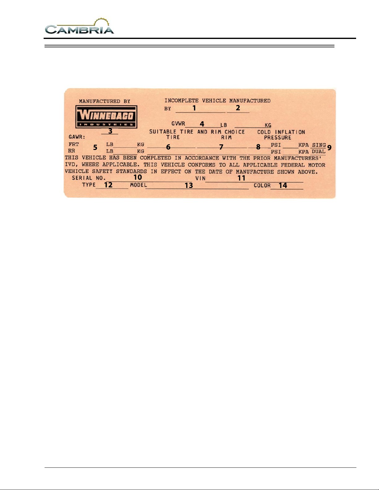
VEHICLE CERTIFICATION LABEL
This label is affixed to the lower driver side armrest panel, driver door or the driver side door jamb,
depending on model. It contains vehicle identification numbers and other important reference information.
EXPLANATION OF DATA
1. Chassis manufacturer.
2. Chassis manufacture date.
3. Month and year of manufacture at Winnebago Industries.
4. Gross Vehicle Weight Rating: Total permissible weight of the vehicle, including driver, passengers, total cargo carried (including all liquids) and equipped with all options.
5. Gross Axle W eight Rating: Total permissible weight allowed for the front and rear axles (listed in pounds and kilograms).
6. Suitable Tire Choice: Tires recommended to meet handling and safety requirements. When replacing any of the tires on your vehicle, always replace with a tire that meets these specifications.
7. Suitable Rim Choice: Wheel rims recommended to meet handling and safety requirements. When replacing any of the rims on your vehicle, always replace with a rim that meets these specifications.
8. Cold Inflation Pressure: Inflation pressures at
Gross Axle Weight Ratings recommended
(while Cold) for the tires originally equipped
be maintained to assure proper handling,
safety and fuel economy.
9. Rear Axle Wheel Configuration: Single or Dual as it relates to the inflation.
10. Serial Number: This is the serial number assigned to the completed vehicle by Winnebago Industries.
11. Vehicle Identification Number (VIN): This
number identifies the chassis on which the
motor home is built. The 10th digit of the VIN
designates the chassis model year. (6=2006,
7=2007, etc.). This information is useful when
ordering chassis repair parts.
12. Type: States the NHTSA designated usage classification for your motor home. MPV signifies a Multi-purpose Passenger Vehicle.
13. Model: Lists the Winnebago product model number of your vehicle.
14. Color: Signifies the color code number of the decor used throughout the vehicle. This number is necessary for ordering replacement cushions, curtains, carpet, etc.
on your vehicle. These pressure levels must
1-3

SECTION 1
INTRODUCTION
SPECIFICATIONS AND CAPACITIES
Model 723D 726A 729H
Length 23' 8"A/23' 8"B 26' 7"B 29' 11"B
Exterior Height1 10' 3"A/10' 6"B 10' 6"B 10' 6"B
Exterior Width 7' 11.2" 7' 11.2" 7' 11.2"
Exterior Storage
2 (cu. Ft.) 19.2 43.0 38.3
Awning Length 13' 17' 19'
Interior Height 6' 5" 6' 5" 6' 5"
Interior Width 7' 8" 7' 8" 7' 8"
Freshwater Capacity w/Heater
Holding Tank Capacity
LP Capacity
4 (gal.) 18 18 18
3 - Black/Gray (gal.) 23/24 29/29 36/29
3 (gal.) 33 43 39
Fuel Capacity (gal.) 55 55 55
GCWR
5 (lbs.) 18,500A/20,000B 20,000B 20,000B
GVWR (lbs.) 11,500A/14,050B 14,050B 14,050B
GAWR - Front (lbs.) 4,600A/4,600B 4,600B 4,600B
GAWR - Rear (lbs.) 7,800A/9,450B 9,450B 9,450B
Wheelbase 158"A/158"B 182"B 220"B
SEE NOTES ON FOLLOWING PAGE.
1-4

SECTION 1
INTRODUCTION
Specifications and Capacities Notes:
®
A Ford
5-speed with tow/haul feature, 4-wheel ABS, 130-amp, alternator, dual air bags (NA w/deluxe graphics)
B Ford
with tow/haul feature, 4-wheel ABS, 130-amp, alternator, dual air bags
1The height of each model is measured to the top of the tallest standard feat ure and is based on the cur b weight
of a typically equipped unit. The actual height of your vehicle may vary by several inches depending on chassis
and equipment variations. Please contact your dealer for further information.
2The load capacity of your motor home is designated by weight, not by volume, so you cannot necessarily use all
available space when loading your motor home.
3Capacities are based on measurements prior to tank installation. Slight capacity variations can result due to
installation applications.
4Capacities shown are tank manufacturer's listed water capacity (W.C.). Actual filled LP capacity is 80% of listing
due to overfilling prevention device on tank.
55Actual towing capacity is dependent on your particular loading and towing circumstances which includes the
GVWR, GAWR, and GCWR as well as adequa te trailer bra kes. Ple ase refer to the chassis oper ator's man ual of
your vehicle for further towing information.
E350 Chassis- 6.8L Super-Duty V10 SOCH Triton® engine, 305-hp, automatic transmission, TorqShift,
®
E450- 6.8L Super-Duty V10 SOCH Triton® engine, 305-hp, automatic transmission, TorqShift, 5-speed
†See Towing Guidelines in Miscellaneous section.
1-5

SECTION 1
INTRODUCTION
OWNER INFORMATION
Owner’s Name______________________________________________________________________
Street Address______________________________________________________________________
City, State/Province, and Zip ___________________________________________________________
Motor Home Serial Number____________________________________________________________
Vehicle Chassis Identification Number (VIN)_______________________________________________
Vehicle Mileage at Time of Delivery______________________________________________________
Selling Dealer Name and Address_______________________________________________________
__________________________________________________________________________________
EMERGENCY INFORMATION
YOUR WINNEBAGO INDUSTRIES DEALER
Name_____________________________________________________________________________
Address ___________________________________________________________________________
__________________________________________________________________________________
Contact Person _____________________________________________________________________
Phone ____________________________________________________________________________
CHASSIS DEALER/SERVICE CENTER
Name_____________________________________________________________________________
Address ___________________________________________________________________________
__________________________________________________________________________________
Contact Person _____________________________________________________________________
Phone ____________________________________________________________________________
INSURANCE POLICY
Company __________________________________________________________________________
Policy Number ______________________________________________________________________
Phone ____________________________________________________________________________
1-6

2007 NEW VEHICLE LIMITED WARRANTY
WINNEBAGO INDUSTRIES, INC.
SECTION 1
INTRODUCTION
WARRANTY COVERAGE TO OWNER
Winnebago Industries, Inc. of Forest City, Iowa, (“Winnebago”)
warrants each new Winnebago and Itasca recreational motor home
to the owner for use in the U.S.A. and Canada as follows:
BASIC LIMITED WARRANTY
WINNEBAGO’S RESPONSIBILITY
Any part of the vehicle subject to this warranty that is found to be
defective in material or workmanship under normal use and
maintenance will be repaired or replaced at Winnebago’s option
without charge to the customer for parts or labor upon notice of the
defect.
WARRANTY PERIOD
The basic Warranty Period is 12 months or 15,000 miles (24,135
kilometers), on the odometer, whichever occurs first. The Warranty
Period for all coverages begins on the date the vehicle is delivered to
the first retail purchaser or first placed in service as a demonstrator
or company vehicle.
ONLY WARRANTY
This limited warranty is the only warranty made or authorized by
Winnebago. Winnebago makes no other promises, representations
or warranties concerning the vehicle or other matters set forth herein.
Winnebago does not authorize any person to create for it any other
obligations or liability in connection with this vehicle.
DEALER’S REPRESENTATIONS EXCLUDED
Winnebago shall not be bound by any undertaking, representation,
or warranty made by any dealers selling its product to any purchaser
of its products.
EXCLUSIVE REMEDY
THE PERFORMANCE OF REPAIRS IS THE EXCLUSIVE REMEDY
UNDER THIS LIMITED WARRANTY OR ANY IMPLIED
WARRANTY. ANY IMPLIED WARRANTY OF MERCHANTABILITY
OR FITNESS FOR A PARTICULAR PURPOSE APPLICABLE TO
THIS VEHICLE ARISING BY WAY OF STATE LAW IS LIMITED IN
DURATION TO THE DURATION OF THIS WRITTEN WARRANTY
AS HEREINBEFORE OR HEREINAFTER PROVIDED.
LIMITATION ON LIABILITY
WINNEBAGO SHALL NOT BE LIABLE FOR INCIDENTAL OR
CONSEQUENTIAL DAMAGES RESULTING FROM BREACH OF
THIS WRITTEN WARRANTY OR ANY IMPLIED WARRANTY.
SUCH DAMAGES INCLUDE, BUT ARE NOT LIMITED TO, LOSS
OF TIME, INCONVENIENCE, OR OTHER CONSEQUENTIAL
DAMAGE INCLUDING EXPENSE FOR GASOLINE, TELEPHONE,
TRAVEL, LODGING, LOSS OR DAMAGE TO PERSONAL
PROPERTY, OR LOSS OF REVENUE.
Some states do not allow limitations on how long an implied warranty
will last or the exclusion or limitation of incidental or consequential
damages, so the above limitations or exclusions may not apply to
you.
ITEMS NOT SUBJECT TO WARRANTY COVERAGE
Chassis, drivetrain and related components*
Wheels*
Tires*
Any other part or component covered by a written warranty issued by
its manufacturer*
Service Items, such as Windshield Wiper Blades, Lubricants, Fluids
& Filters
Adjustments
*These items are covered under the manufacturer’s individual
warranty.
ADDITIONAL EQUIPMENT NOT COVERED
Winnebago cannot and does not accept any responsibility in
connection with any of its motor homes for additional equipment or
accessories installed at any dealership or other place of business, or
by any other party other than Winnebago. Such installation of
equipment or accessories by any other party will not be covered by
the terms of this warranty.
36 MONTH/36,000 MILE STRUCTURAL WARRANTY
At the expiration of the Basic Coverage and for the remainder of the
period of 36 months or 36,000 miles (57,924 kilometers), on the
odometer, whichever occurs first, Winnebago Industries warrants the
following:
1. Structural defects of the subfloor, floor, and slide-out room
assembly. Floor lamination failure and lamination failure of the
subfloor panels and risers are covered by the structural
warranty.
2. Body Thermo-Panel
against delamination. Body Thermo-Panel
bonding of the exterior skin and the interior paneling to an
insulating core material. Delamination (separation of layers)
caused by other factors such as physical damage or failed
sealants is not covered by this warranty.
This warranty gives you specific legal rights and you may also have
other rights which vary from state to state.
Also, this warranty shall not apply to failures, damage or
malfunctions resulting from normal wear, misuse, abuse, negligence,
alteration, accident, fire, improper repair of the vehicle or failure to
follow recommended maintenance requirements.
OWNER’S RESPONSIBILITY-CARE AND MAINTENANCE
It is the owner’s responsibility to perform the care, maintenance and
proper load distribution described in the operator’s manual which
accompanies your motor home. Any damage which results to your
vehicle as a result of your failure to perform such duties, is not
covered.
Damage to appearance items such as fiberglass, metal, paint,
fabrics and trim, may occur during manufacturing or transporting.
Normally, any factory defect or damage is corrected at the factory. In
addition, dealers are obligated to inspect each vehicle upon delivery
to them and prior to delivery to you. You should also immediately
inspect appearance items and advise your selling dealer of any
discrepancies. Damage and normal deterioration due to use and
exposure is not covered by this warranty.
Lamination of the sidewalls and backwall
Lamination is the
1-7

SECTION 1
INTRODUCTION
OBTAINING WARRANTY REPAIRS
While any Winnebago Industries motor home dealer can perform
warranty service, we recommend you return to the dealership that
sold you your vehicle. If you are touring or have moved, contact any
Winnebago Industries motor home dealer in the United States or
Canada for warranty service.
If a part of the system covered by this limited warranty fails to
function or requires service during the warranty period:
1. Promptly take the vehicle to the selling dealer for repair or
inspection.
2. Written notice of defects must be given to the selling dealer and
manufacturer.
3. If the dealer is incapable of making the repairs, request that he
contact Winnebago Industries, Inc.
4. If, after the above steps are completed and the repair is not
made, the customer should contact Winnebago Industries, Inc.,
605 West Crystal Lake Road, P.O. Box 152, Forest City, Iowa
50436, Attention: Owner Relations Department (800-537-1885)
and furnish the following information:
The complete serial number of the vehicle
Date of retail purchase
Selling dealer’s name
Nature of the service problem, and a brief explanation of
the steps or service the dealer has performed, and the
results obtained. The customer may be directed to another
dealer or service center for repairs to be completed, if such
a dealer or service center is better able to complete the
repair.
Winnebago Industries may, at its option, request the vehicle be
returned to Forest City, Iowa for repair. If the customer refuses to
allow repairs to be performed at the Forest City, Iowa facility, the
warranty on that repair will be voided.
5. If after the above steps are completed and the repairs are not
satisfactory, the customer may contact the Service
Administration Manager of Winnebago Industries, and request a
customer relations board meeting to resolve the problem. This
action, however, is not mandatory.
6. Certain components are covered by warranties provided by
individual component manufacturers. Please refer to the
component’s information supplied in the vehicle’s InfoCase.
COMMENCEMENT OF ACTIONS
CALIFORNIA
Winnebago Industries participates in the Consumer Arbitration
Program for Recreation Vehicles (CAP-RV). This third-party dispute
resolution program is available, at no charge to you, to settle
unresolved warranty disputes for recreational vehicles. This dispute
resolution program reviews eligible product and service related
complaints involving warranty covered components.
To find out more about the program, or to request an
application/brochure, please call the Arbitration Administration office
toll-free 800-279-5343.
The CAP-RV program operates as a certified mechanism under the
review of the California Arbitration Certification Program. You must
utilize the arbitration program before claiming rights conferred by 15
USC section 2310 (Uniform Commercial Code) or Civil Code section
1793.22(b) (Tanner Consumer Protection Act). You are not required
to use the program if you choose to seek redress by pursuing rights
and remedies not created by those laws.
:
Any action for breach of The Basic Limited or Structural Warranty or
any implied warranty shall be commenced within one-year after
expiration of the warranty.
CHANGES IN DESIGN
Winnebago Industries, Inc. reserves the right to make changes in
design and changes or improvements upon its products without
imposing any obligation upon itself to install the same upon its
products theretofore manufactured.
NEW YORK
If your motor home has been repaired three or more times for the
same nonconformity, defect, or condition, or if your motor home has
been out of service by reason of repair for twenty-one days, Section
198-a of the General Business Law of the State of New York
requires you to provide written notice by certified mail, return receipt
requested, to Winnebago Industries or its authorized dealer before
making any claim under that section of the law. If you do have
problems with your motor home, you should provide written notice to
Winnebago Industries at the following address:
:
Winnebago Industries, Inc.
605 West Crystal Lake Road
P.O. Box 152
Forest City, Iowa 50436
Attn: Owner Relations
0306
1-8

SECTION 2 SAFETY / PRECAUTIONS
GENERAL WARNINGS
• Only seats equipped with seat belts are to be
occupied while the vehicle is moving.
• Make sure all passengers have seat belts
fastened. Lap belts should fit low on the hips
and upper thighs. The shoulder belt should be
positioned snug over the shoulder.
• For pregnant women, the lap belt should be
placed under the abdomen and across the
upper thighs. The shoulder belt should be
positioned across the center of the chest.
Consult your doctor if you have any
questions.
• Child restraints should be installed properly
according to manufacturer’s instructions. See
“Child Restraints.”
• All moveable or swiveling seats should be
placed and locked in forward facing positions
while the vehicle is moving.
• Never let passengers stand or kneel on seats
while the vehicle is moving.
• Sleeping facilities are not to be utilized while
vehicle is moving.
• Examine the escape window and be familiar
with its operation.
• Inspect the fire extinguisher monthly for
proper charge and operating condition. This
should also be done before beginning a
vacation or any extended trip.
• Driving through water deep enough to wet the
brakes may affect stopping distance or cause
the vehicle to pull to one side. Check brake
operation in a safe area to be sure they have
not been affected. Never operate any vehicle if
a difference in braking efficiency is
noticeable.
• Adverse weather conditions and extremes in
terrain may affect handling and/or
performance of your vehicle. Refer to your
chassis manual for related information.
PROPANE GAS LEAK DETECTOR
Your coach is equipped with one of the
propane gas leak detectors shown below. The
leak detector sounds an alarm if an unsafe
amount of propane gas is present inside the
coach.
5 - DASH / AUTO
DRIVING SAFETY
• Do not attempt to adjust the driver’s seat while
the vehicle is moving.
• Do not adjust tilt steering in a moving vehicle.
• Do not operate the cruise control on icy or
extremely wet roads, winding roads, in heavy
traffic, or in any other traffic situation where
a constant speed cannot be maintained.
• Use care when accelerating or decelerating on
a slippery surface. Abrupt speed changes can
cause skidding and loss of control.
Propane Gas Leak Detectors (typical)
Because propane gas is heavier than air, the
leak detector is located on a cabinet face near the
floor of the coach.
2-1
SECTION 2
SAFETY / PRECAUTIONS
WARNING
Never use an open flame to test for gas
leaks. When testing for gas line leaks with
a soapy water solution, DO NOT use a
detergent containing ammonia or
chlorine. These substances may
generate a chemical reaction causing
corrosion to gas lines, resulting in
dangerous leak conditions.
Power Connection
The propane gas leak detector is powered by
the house batteries. If the auxiliary battery switch
is shut off or the battery cable is disconnected
from the batteries, the alarm will not work. The
propane gas leak detector fuse or circuit breaker
is located in the 12-volt house electrical load
center.
Because the propane gas leak detector is
connected to the house battery, it is always
drawing a small amount of current. Even though
this current draw is slight, it could drain the house
battery during storage periods when the house
battery will not be charged regularly by the
engine or shoreline. Turn the Aux. Batt switch
OFF to avoid current drain during storage
periods.
Further Information
See the manufacturer’s information in your
InfoCase for further instructions on nuisance
alarms and care and testing of the propane gas
leak detector.
CARBON MONOXIDE WARNING
WARNING
Avoid inhaling exhaust gases, as they
contain carbon monoxide, which is a
colorless, odorless and poisonous gas.
The best protection against carbon monoxide
entry into the vehicle body is a properly
maintained engine exhaust and ventilation
system. It is recommended that the exhaust
system and body be inspected by a qualified
motor home service center.
• Each time the vehicle is serviced for an oil
change.
• Whenever a change in the sound of the
exhaust system is noticed.
• Whenever the exhaust system, underbody or
rear of the vehicle is damaged.
To allow proper operation of the vehicle’s
ventilation system, keep front ventilation inlet
grill clear of snow, leaves or other obstructions at
all times. DO NOT OCCUPY A PARKED
VEHICLE WITH ENGINE RUNNING FOR
AN EXTENDED PERIOD.
Do not run engine in confined areas, such as a
garage, except to move vehicle into or out of the
area.
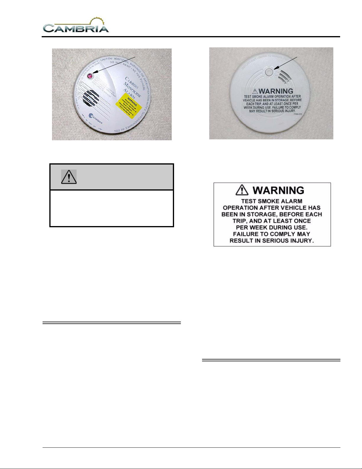
CARBON MONOXIDE ALARM
Your coach is equipped with a carbon
monoxide (CO) alarm located on the ceiling in
the bedroom area. The CO alarm is powered by a
9-volt battery and has a sensor that is designed to
detect toxic carbon monoxide gas fumes
resulting from incomplete combustion of fuel. It
will detect CO gas from any combustion source
such as the furnace, gas range/oven, water heater,
refrigerator, chassis engine, and electric
generator engine.
2-2
SECTION 2
SAFETY / PRECAUTIONS
Press button to test
Carbon Monoxide Alarm
WARNING
Failure to replace this product by the
“REPLACE BY DATE” printed on the
alarm cover may result in death by
Carbon Monoxide poisoning.
Press button to test
Smoke Alarm
The following label is affixed to the smoke
alarm.
Further Information
Please read the information provided by the
manufacturer, which is included in your
InfoCase. It includes information on precautions,
operational testing, and battery replacement.
Replacement
When replacing this alarm, we recommend
replacing only with a similar model. Other brands
may not be recommended for RV application.
SMOKE ALARM
Your motor home is equipped with a smoke
alarm located on the ceiling in the lounge area.
The smoke alarm is powered by a 9-volt battery
and has a sensor that is designed to detect smoke.
Further Information
See the manufacturer’s information in your
InfoCase for further instructions on battery
replacement and testing of the smoke alarm.
Replacement
When replacing this alarm, we recommend
replacing only with a similar model. Other brands
may not be recommended for RV application.
We recommend obtaining a replacement from
your Winnebago Industries dealer.
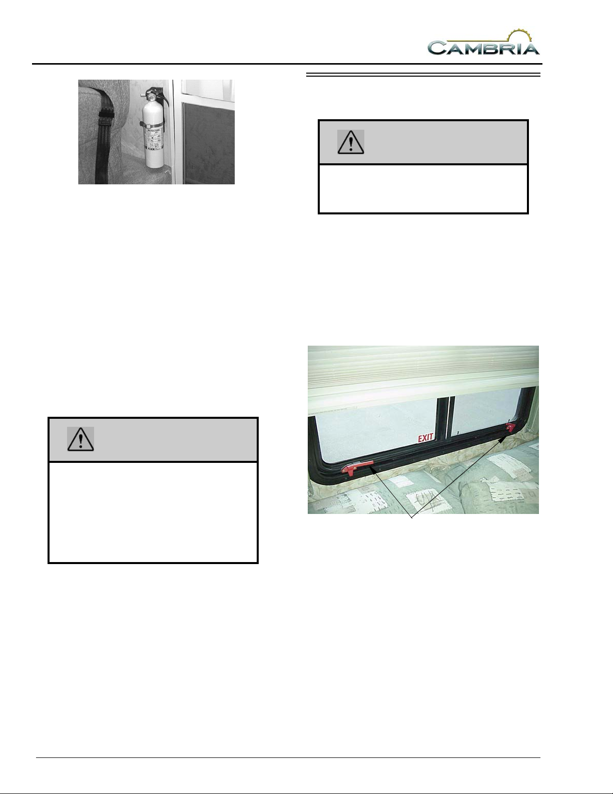
FIRE EXTINGUISHER
A dry chemical fire extinguisher is located on
the wall or floor near the main entrance door.
2-3
SECTION 2
SAFETY / PRECAUTIONS
Fire Extinguisher
(typical installation - your coach may
vary according to model and floorplan)
We recommend that you become thoroughly
familiar with the operating instructions displayed
on the side of the fire extinguisher or in the
information supplied in your InfoCase.
We also recommend that you inspect the fire
extinguisher for proper charge at least once a
month in accordance with National Fire
Protection Association (NFPA)
recommendations as stated on the label.
If the charge is insufficient, the fire
extinguisher must be replaced.
EMERGENCY EXITS
WARNING
Use care when exiting emergency
window, as broke n glass may be present
in the exit area.
Escape Window
The bedroom escape window is secured by
two red safety latches at the bottom of the
window.
To open, lift both latches up and toward the
center of the window, then push outward near the
bottom of the window.
WARNING
Do not test the fire extinguisher by
discharging it. Partial discharge can
cause leakage of pressure or contents
which would render the unit inoperative
when needed. When using the fire
extinguisher , aim the spray at the base of
the fire.
Replacement
If, for any reason, you must replace the fire
extinguisher, the replacement must be the same
type and size, or larger, as the one originally
supplied in your coach. We recommend
obtaining a replacement only from your
Winnebago Industries dealer or a reliable RV
parts supplier.
Escape Window - Lift latch
handles upward to open.
Using Slider Windows As Emergency Exits
Some coaches are required to have a slider
window as an alternate exit. This window will be
marked EXIT and have a red handled latch.
2-4

Pull latch outward to slide window open
Most slider windows along the side of any
motor home can also be used as alternate
emergency exits, should the need arise.
To use a slider windows as an exit, first slide
the window open, then either slide the screen
open or push the screen material out, depending
on window construction.
FORMALDEHYDE INFORMATION
WARNING
Some components in this vehicle contain
formaldehyde based adhesives which
may release formaldehyde fumes into the
air for an unknown period of time until total
dissipation occurs. Individuals who are
allergic to formaldehyde gas fumes may
experience irritation to eyes, ears, nose
and throat. Reaction in infants may be
more severe. Although long range effects
are not well understood, testing to date
has not revealed any serious health
effects in humans at the level of emission
from these products.
SECTION 2
SAFETY / PRECAUTIONS
MOLD, MOISTURE AND YOUR MOTOR HOME
What is Mold?
Molds are part of the natural environment.
They are as old as the Earth itself. And mold
spores are almost everywhere at some level
waiting to grow. Mold plays a part of nature by
breaking down dead organic matter such a fallen
leaves and dead trees. Indoors, however, mold
growth should be avoided. Molds reproduce by
means of tiny spores. Those spores are invisible
to the naked eye and float throughout the outdoor
and indoor air. Because of the nature of the use of
a motor home, it is natural for a motor home to be
introduced into an environment with mold
spores.
Mold is a plant and requires its own special
environment to grow. That environment includes
organic materials, nutrients, moisture, and proper
temperature.
How Can I Avoid Mold?
To reduce the ability for mold to grow, you
must reduce what constitutes its growth
environment. Mold can grow with the smallest of
a nutrient base. Just small amounts of dirt or dust
on the carpet can be enough to allow the mold
process to begin. Keep the environment as clean
as possible. Vacuum the carpet. Clean food spills
thoroughly and quickly. Avoid grease buildup
near the stove or sink. Clean the exhaust fan
above the stove often.
Minimize moisture in your motor home and
keep humidity low. Clean spills quickly. Do not
allow condensation to build up. You can open
windows and vents to minimize condensation.
Use of the air conditioner can assist in removing
moisture from the air. Avoid leaks and if leaks do
occur, make repairs promptly.
Avoid bringing mold into your motor home.
Plants, cloths, books, and other household items
may already have mold present. It is easy to
transfer mold into your motor home
environment.
2-5
SECTION 2
SAFETY / PRECAUTIONS
Monitor your motor home. Periodically check
those hidden areas in corners, closets, and
cabinets to assure mold is not present.
What if I Have Mold?
If mold develops, clean the area with a
concentrate of soap and bleach. Items that
contain mold that cannot be cleaned should be
removed from the vehicle.
Can Mold Harm Me?
The effects of mold and airborne mold spores
may cause irritation to some people. Experts
disagree on the level of exposure that may cause
health concerns.
If Mold Is Present, What Will Winnebago Industries Do?
If Winnebago Industries determines that mold
is present in the Winnebago/Itasca motor home
as a result of a manufacturing defect reported to
Winnebago Industries within the limited
warranty period, Winnebago will clean the
affected areas and/or replace affected items as it
deems necessary. This is the extent of coverage
provided by Winnebago Industries. Winnebago
Industries, however, will not assume
responsibility for mold deemed to be a result of a
motor home users lack of timely and appropriate
action to mitigate circumstances should a
problem occur.
If Winnebago Industries determines that mold
is present due to conditions it determines is not a
result of a manufacturing defect found within the
warranty period, Winnebago Industries will not
provide any financial assistance to the repair of
the condition.
If you wish to try jump starting the engine
using another vehicle or booster system, see your
chassis manual for connecting jumper cables to
the automotive electrical system.
WARNING
Do not attempt to push start this vehicle.
Damage to the transmission or other
parts of the vehicle will occur.
ENGINE OVERHEAT
If you see or hear steam escaping from the
engine compartment or have any other reason to
suspect an extreme engine overheating condition,
pull the vehicle over to the roadside as soon as it
is safe to do so, stop the engine and get all
passengers out of the vehicle.
WARNING
Operating a vehicle under a severe
overheating condition can result in
damage to the vehicle and may result in
personal injury.
For information on what to do in case of
overheating, consult your chassis manual.
© Copyright Winnebago Industries, Inc. All
rights reserved.
JUMP STARTING
If your coach will not start from the chassis
battery, try using the battery boost switch to
divert power from the house batteries to the
starter. (See either “Battery Boost Switch” or
“Aux Start Switch.”)
2-6
SECTION 3 DRIVING YOUR MOTOR HOME
The information in this section refers only to
features installed or adapted to the dash and
driver compartment area by Winnebago
Industries. It also includes passenger seating in
the living area of the coach.
See your chassis manual for all original
chassis related controls, instrumentation,
switches and other features. This includes items
such as cruise control, climate controls, gauges,
wipers, lights, front seats and three-point safety
belts, etc.
FRONT SEATS
The driver and co-pilot seats may be
independently adjusted to suit individual
preference.
See your chassis manual for instructions on
seat adjustments.
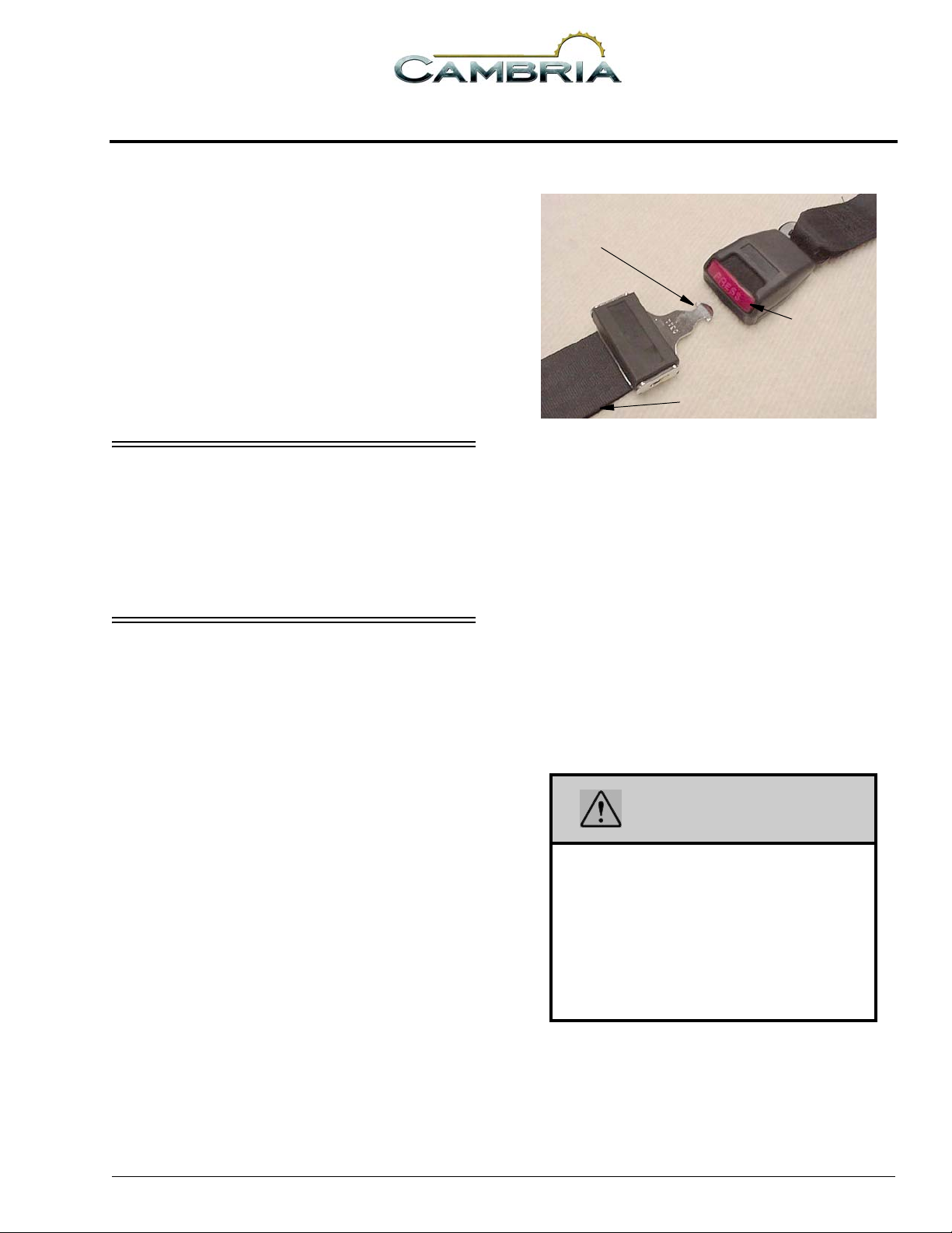
SEAT BELTS
1- Insert tab into buckle
slot until it ‘clicks’ and is
locked
3- Press to
release
2- Pull strap to tighten
Adjustment:
To lengthen belt, swivel the tab end at a right
angle to belt and pull strap to desired length. To
shorten, pull loose end of belt.
To Fast en:
Be sure belt is not twisted. Grasp each part of
the belt assembly and push tongue into buckle.
Adjust to a snug fit by pulling the loose end away
from the tongue.
Seats intended for occupancy while the
vehicle is in motion are equipped with seat belts
for the protection of the driver and passengers.
Lap Belts
The lap belts must be worn as low as possible
and fit snugly across the hip area. Always sit
erect and well back into the seat. To gain full
protection of the safety belt, never let more than
one person use the same safety belt at any one
time, and do not let the safety belts become
damaged by pinching them in the doors or in the
seat mechanism. After any serious accident, any
seat belts which were in use at the time must be
inspected and replaced if necessary.
To Release:
Press button in center of buckle and slide
tongue out of buckle.
WARNING
5 - DASH / AUTO
Snug and low belt positions are essential.
This will ensure that the force exerted by
the lap belt in a collision is spread over the
strong hip area and not across the
abdomen, which could result in serious
injury.
Only seats equipped with seat belts are to
be occupied while vehicle is in motion.
Lap/Shoulder Belts
See your chassis manual for instructions on
proper fastening, adjustment and releasing of lap/
shoulder belts.
3-1
SECTION 3
DRIVING YOUR MOTOR HOME
Seat Belt Care and Cleaning
• Be careful not to damage the belt webbing and
hardware. Take care not to pinch them in the
seat or doors.
• Inspect the belts and hardware periodically.
Check for cuts, frays, and loose parts.
Damaged parts should be replaced. Do not
remove or modify the belt system.
• Keep belts clean and dry. If the belts need
cleaning, use only a mild soap and water
solution. Do not use hot water. Do not use
abrasive cleaners, bleach or dyes. These
products may weaken the belts.
• Replace any belt assembly that was used
during a severe impact. Replace the complete
assembly even if damage is not apparent.
CHILD RESTRAINTS
A properly installed and secured child
restraint system can help reduce the chance or
severity of personal injury to a child in an
accident or during a sudden maneuver. Children
may have a greater chance of being injured in an
accident if they are seated in a child restraint
system which is not properly secured.
A child restraint system is designed to be
secured in a vehicle seat by a lap belt or the lap
belt portion of a lap-shoulder belt.
When purchasing a child restraint system,
follow these guidelines:
1. Look for the label certifying that it meets all
applicable safety standards.
2. Make sure that it will attach to your vehicle
and restrain your child securely and
conveniently so that you are able to install it
correctly each time it is used.
3. Be certain that it is appropriate for the child's
height, weight and development. The
instructions and/or the regulation label
attached to the restraint typically provides this
information.
4. Review the instructions for installation and
use of the restraint. Be sure that you
understand them fully and can install the
restraint properly and safely in your vehicle.
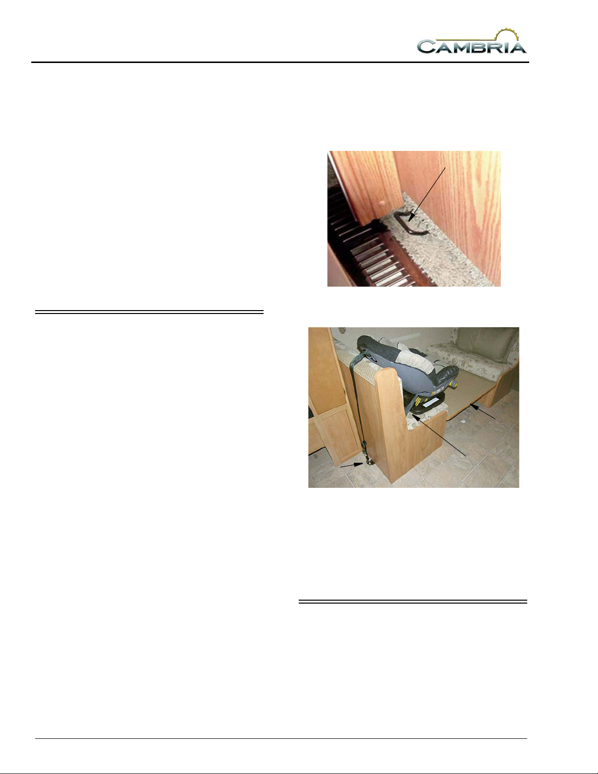
Tether Anchor Loop
If your coach has a dinette, it may be equipped
with a child seat tether anchor loop located on the
floor directly behind the forward facing dinette
seat.
Tether Anchor Loop
The dinette table must be in the lowered
position when a child seat is in use.
1
3
2
1. Lower the dinette table.
2. Route the tether over the top of the dinette seat
back and hook it to the anchor loop on the floor .
3. Fasten the lap belt.
See the child seat maker’s specific
instructions for proper attachment and
adjustment of the tether and seat belts.
KEYS
Your motor home is supplied with several
keys. In addition to the chassis manufacturer’s
ignition key, you receive keys for the entrance
door and exterior compartment doors.
Keys have an identification number, either a
small metal tag or stamped into the key head.
These numbers are recorded on the vehicle’s
3-2
component model/serial sheet which is included
in your InfoCase. In case keys are lost or stolen,
your dealer or a locksmith can provide you with
duplicate keys or modify the locks.
HAZARD WARNING FLASHERS
The hazard warning flashers provide
additional safety when the vehicle must be
stopped on the side of the roadway and presents a
possible hazard to other motorists. When the
flashers are on, it serves as a warning to other
drivers.
See your chassis manual for instructions on
activating, operating and canceling hazard
warning flashers.
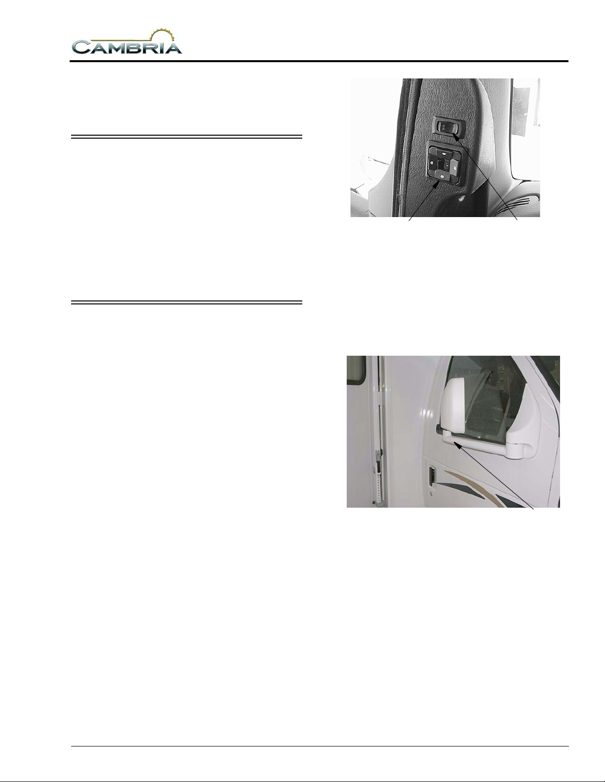
MIRRORS - EXTERIOR
Always adjust mirrors for maximum rear
visibility before driving off. Make sure the seat is
adjusted for proper vehicle control and that you
are sitting back squarely into the seat.
The mirrors may also contain heating
elements to defog or de-ice the mirror glass
during cold weather operation. An ON-OFF
switch for the mirror heaters is located near the
remote mirror controls.
The ignition switch must be on to operate
mirror controls and heaters.
SECTION 3
DRIVING YOUR MOTOR HOME
irror Adjustment Control
Mirror surface tilts in direction
of arrow button pressed.
Middle switch selects L or R
mirror to adjust.
Center position is ‘neutral’ to
disable arrow buttons and
prevent misadjustment of
mirrors.
Mirror Heat Switch
The mirrors can be folded back
against the cab doors if needed.
Mirror Head Adjustment
If you cannot adjust a mirror properly using
the control switch, the mirror may need a coarse
adjustment by rotating the mirror head.
3-3
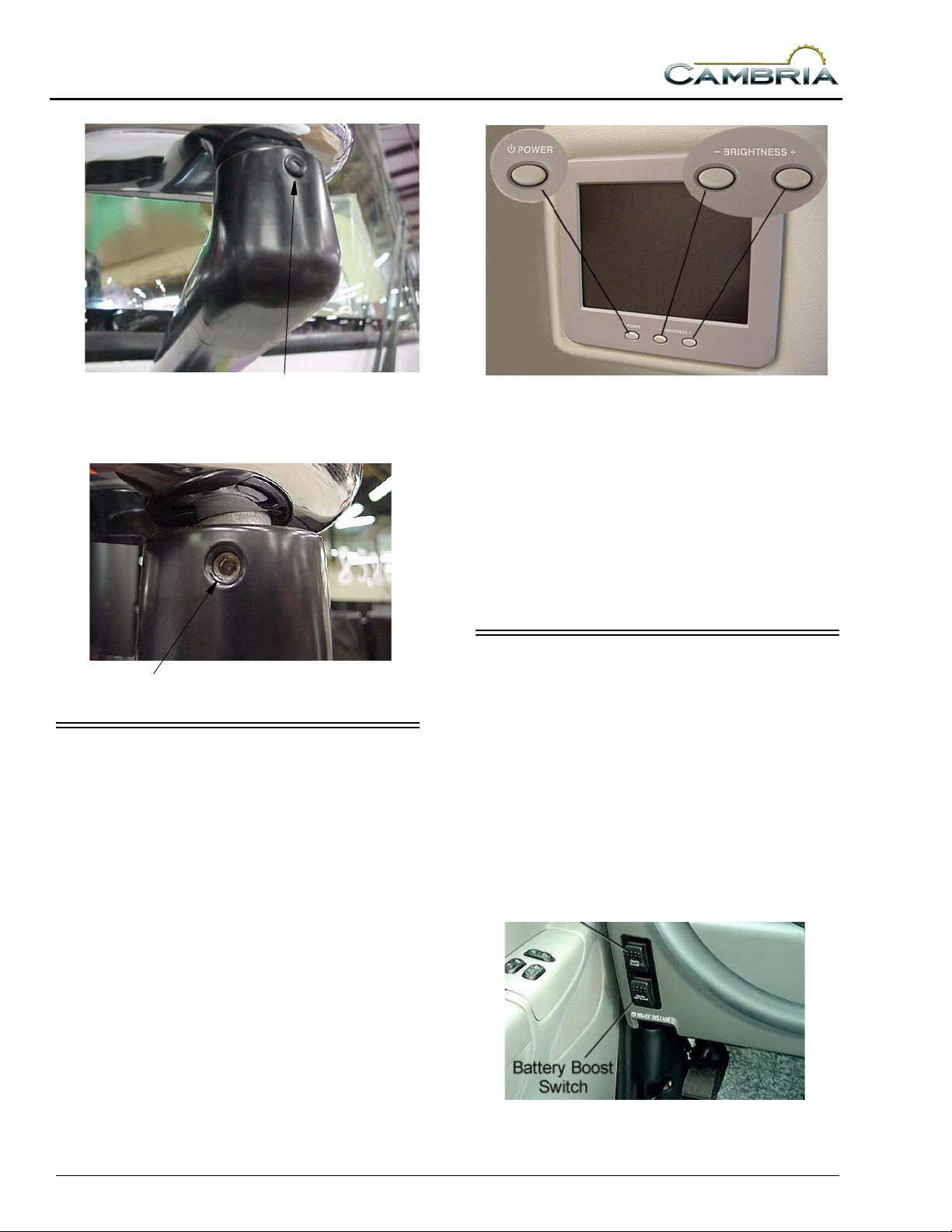
SECTION 3
DRIVING YOUR MOTOR HOME
Mirror Pivot Lock
Unscrew protective cap and
loosen Allen head set screw
Allen Head Set Screw*
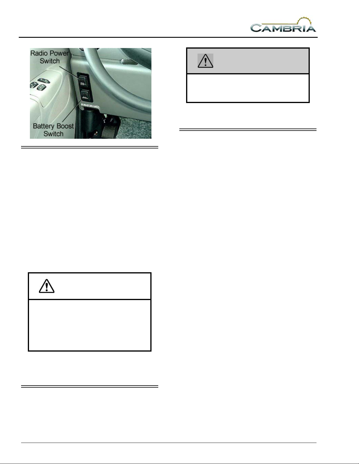
REARVIEW MONITOR SYSTEM
–If Equipped
The rearview camera monitor system lets you
see what’s directly behind your coach for
maneuvering assistance and safety.*
The compact rearview monitor is mounted in
a housing on the ceiling of the driver
compartment.
• Auto On- Monitor ‘wakes up’ automatically
when transmission is shifted into Reverse.
• Power- Press to turn monitor on while driving
or parked.* Key must be on.
• Brightness- Press + or - to increase or
decrease monitor brightness.
Further Information
If your motor home is equipped with this
optional system, refer to the InfoCase for further
instructions provided by the manufacturer.
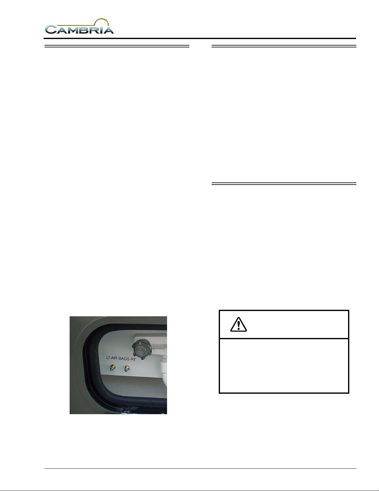
BATTERY BOOST SWITCH
This switch can be used to draw emergency
starting power from the house batteries to start
the engine if the chassis battery is discharged.
Press and hold in the ON position while
turning ignition key for emergency starting
power.
NOTE: The Aux. Battery Disconnect switch near
the entrance door must be ON and house
batteries must be sufficiently charged for
this feature to work.
3-4

AUTO AIR CONDITIONER/ HEATER
See your chassis manual for operating
information on driver and passenger comfort
controls – air conditioner, heater, defroster and
ventilation.
NOTE:The dash air conditioner is not designed
to cool the entire interior of the coach,
but is intended only to provide cooling
the cab area.
IN-DASH RADIO
The radio in your coach can receive AM/FM
stereo and Weather band stations. It also has a
compact disc (CD) player for your listening
enjoyment through quality high-output speakers
located in several areas of the coach.
SECTION 3
DRIVING YOUR MOTOR HOME
Radio Remote Controls
A steering wheel mounted remote control for
the radio lets you change radio stations or CD
selections without taking your eyes off the road
or hands off the wheel. See the radio owner’s
guide in your InfoCase for remote control
instructions.
Please refer to the manufacturer’s operating
guide in your InfoCase for detailed instructions
on programming preset station buttons and using
this full-featured radio/audio system.
Satellite Radio
–If Equipped
Your coach may be equipped with a Sirius
satellite radio receiver that plays through your
radio. See the radio manufacturer’s information
in your InfoCase for programming and operating
instructions.
NOTE: If your Sirius tuner is not activated,
follow the instructions in the radio
owners manual in your InfoCase for the
phone number to call and procedure to
access the Sirius Tuner ID Number
(ESN).
Radio Remote Control
(typical)
An additional hand-held remote allows these
same conveniences for the passenger. The handheld radio remote is in your InfoCase.
Radio Power Switch
The radio power switch on the dash lets you
connect the dash radio to the coach batteries
when the ignition switch is turned off for
listening while parked. This prevents accidental
draining of the chassis battery by prolonged use
of the radio.
NOTE:The Aux. Battery Disconnect switch must
be on while listening to the dash radio
because the audio relay is powered by
house batteries. If the Aux Batt switch is
off, the speakers will not emit sound.
3-5
SECTION 3
DRIVING YOUR MOTOR HOME
ENGINE COOLING SYSTEM
Do not remove the radiator cap while engine
and radiator are still hot. Always check coolant
level visually at the see-through coolant
reservoir.
NOTE: Your chassis engine cooling system is
filled with special extended-life coolant
that is not the same as common antifreeze available at retail outlets.
The coolant system MUST be refilled or
topped up with the same type of coolant
as equipped to maintain the special longlife properties.
CAUTION
When refilling the coolant system of a
vehicle equipped with a rear auxiliary
automotive heater and motoraid water
heater, be sure to allow for additional
coolant capacity of the heater and its
supply and return hoses.
Refer to your chassis manual for information
and precautions on filling, servicing and
checking the fluid level.
TIRES
Improper tire pressure can result in tire
overloading and abnormal wear and also affects
handling, ride characteristics and fuel economy.
WARNING
Make sure all replacement tires are of the
same size and ply rating as those
installed as original equipment.
See your Vehicle Certification Label for tire
information.
SUSPENSION ALIGNMENT AND TIRE BALANCE
The front suspension and steering system of
this vehicle was factory aligned using highly
accurate equipment prior to delivery to the
dealership. However, alignment should be
checked and adjusted, after you have fully loaded
the motor home according to your personal
needs. Thereafter, the alignment should be
periodically inspected to help prevent uneven tire
wear.
Any excessive or abnormal tire wear may
indicate worn or misaligned suspension or
steering, unbalanced tire or other tire/suspension
problem.
Alignment can be affected by worn steering/
suspension parts or by incidents which happen
during driving, such as hitting a curb, pothole or
railroad track, etc. Improper alignment can cause
tires to roll at an angle and wear unevenly. It may
also cause the vehicle to “pull” to the right or left.
Have your dealer inspect your vehicle’s
suspension and steering components periodically
for misalignment or wear.
Out-of-balance tires will not roll smoothly and
can lead to vibrations and uneven tread wear such
as cupping and flat spots. Tires may need to be
balanced if uneven wear is detected or if ride
comfort decreases noticeably.
See your chassis manual for further
information.
3-6
SECTION 3
DRIVING YOUR MOTOR HOME
AIR SPRINGS - REAR
–If Equipped
The rear air helper springs (air bags) are an
enhancement to the standard suspension system
to provide adjustable load and ride conditions.
This feature is not intended to increase the load
capacity of the rear axle or vehicle.
Adjustment
Check and adjust the air bag pressure
periodically to maintain optimal ride and
handling characteristics according to cargo
weight.
Too much air pressure in the air helper springs
will result in a firmer ride, while too little air
pressure will allow the air helper spring to bottom
out over rough road conditions. Too little air
pressure will also not provide the improvement in
handling that is possible.
The air bags can be adjusted independently if
necessary to equalize a load, however we
recommend maintaining the same pressure in
both air bags whenever possible to ensure that the
vehicle remains level.
Recommended Pressure:
start at 20-25 psi
Minimum Operating Pressure: 10 psi
Maximum Operating Pressure: 100 psi
LIGHTS
All exterior lights should be checked for
proper operation each time the vehicle is
prepared for a trip. Any bulbs which fail to light
should be checked and replaced, when necessary,
with a new bulb of the same size. A failure of
more than one light, such as both taillights not
operating, may indicate a burned out fuse. Check
fuse and replace with one of the same rating
when necessary. If a fuse is not the cause of the
problem, the wiring system should be checked
immediately by an authorized service center.
Refer to your chassis manual for further
information.
MOUNTAIN DRIVING
Special techniques must be used when driving
in mountainous or hilly country.
Climbing A Hill
The transmission will automatically
downshift as needed to climb most hills. If the
hill is long or very steep, however, you may need
to manually shift to a lower gear to keep the
transmission from repeatedly upshifting and
downshifting. Select the lowest adequate gear
range for the duration of the incline. See your
chassis manual for specific information.
Rear Air Helper Spring Valves
(located in water service center compartment)
CAUTION
Observe the engine temperature gauge
more frequently than normal. If
overheating occurs, pull off to the side of
the road and allow the engine to
thoroughly cool before refilling the
radiator and restarting the engine.
Descending A Hill
When going down a long grade, you may need
to manually shift to a lower gear rather than
keeping your foot on the brake pedal. A lower
gear will allow the engine to provide a degree of
braking action. Holding your foot on the brake
pedal for an extended period may cause brakes to
3-7

SECTION 3
DRIVING YOUR MOTOR HOME
overheat, which could cause you to lose control
of the vehicle. See your chassis manual for
specific information.
3-8
SECTION 4 APPLIANCES & SYSTEMS
The appliances installed in your motor home
are manufactured by reputable RV appliance
makers and have been tested by independent
laboratories to meet all applicable standards and
codes set for RV appliances.
REFRIGERATOR
The refrigerator in your coach can operate
from either of two energy sources available to the
motor home:
• 120-Volt AC electric
• Propane gas
To be able to use both types of energy, the
refrigerator does not have a compressor like
household refrigerators. Instead, it uses an
ammonia-water solution for cooling. Basically,
ammonia vapor is distilled from the solution by
heat produced from either propane gas flame or
electrical heat element. The ammonia vapor is
then carried to the finned condenser where it
liquefies. The liquid then flows to an evaporator
where it creates cooling by evaporation. The
ammonia circulates back into the water solution
and the cooling cycle continues.
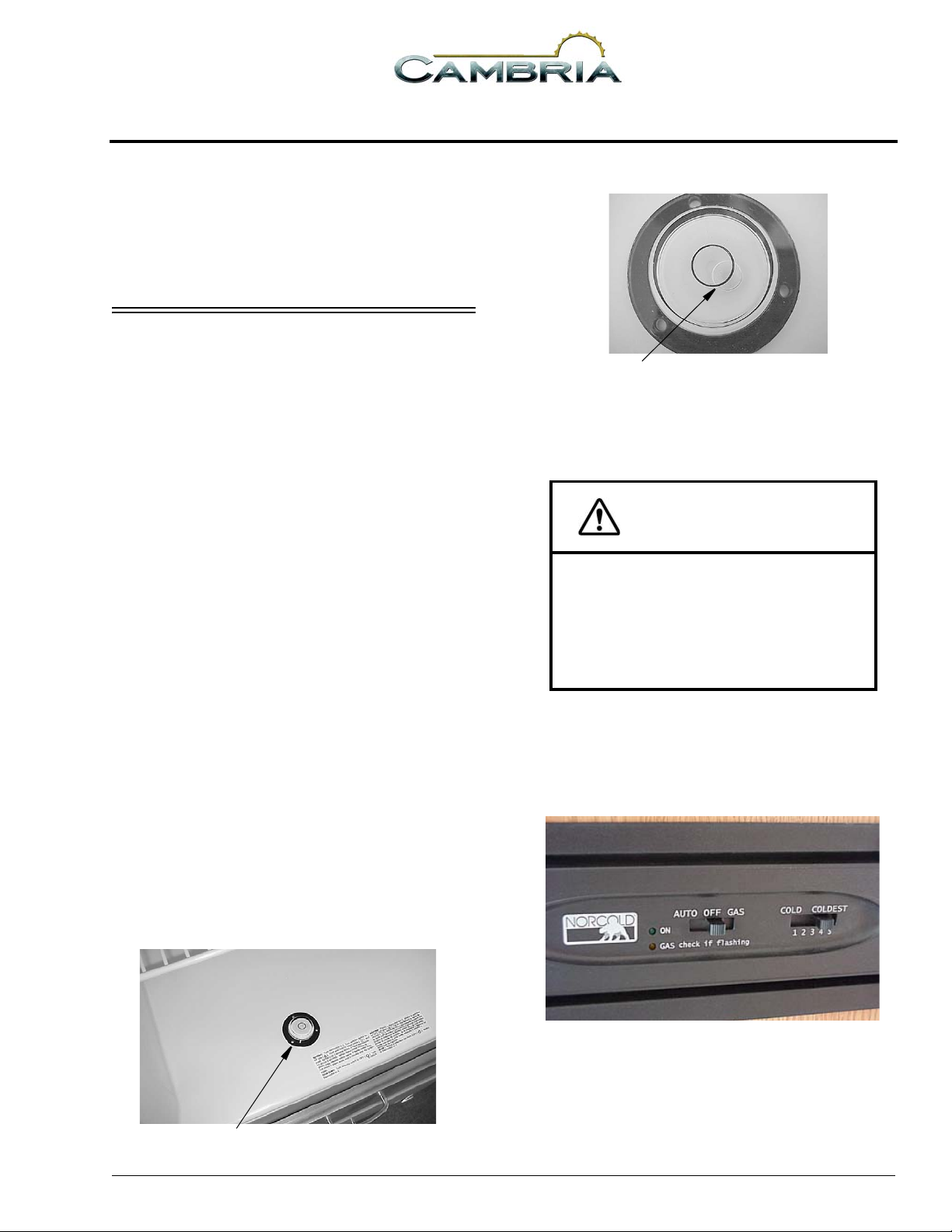
Leveling
Before operating the refrigerator when the
motor home is stationary, place a small level on
the bottom of the refrigerator and make certain
the unit is level. If over 1/2 of the bubble is inside
the circle in any direction, the coach is level
enough for continuous operation of the
refrigerator while parked.
Bubble must be at least 1/2 inside circle
Normal vehicle leveling to provide comfort
for the occupants is satisfactory for refrigerator
operation.
CAUTION
To prevent permanent damage to the
refrigerator cooling unit, turn the
refrigerator off if the vehicle will be p arked
on an incline of over 3° side-to-side or 6°
front-to-rear (such as steep driveways or
parking lots, etc.) for more than one hour.
Basic Operation
Slide the control switches to the operating
positions described and observe the indicator
lights.
5 - DASH / AUTO
Place bubble level in bottom of refrigerator
• Gas- Refrigerator will operate on gas from the
propane tank if the main valve is open and the
tank contains gas.
4-1

SECTION 4
APPLIANCES & SYSTEMS
• Auto- Refrigerator will operate on 120-VAC
household current if the shoreline is
connected or the auxiliary generator is
running. If electricity is lost, it will
automatically switch over to Gas operation if
gas is available.
• Temperature Setting- Start at the ‘coldest’
setting to ensure coldest temperature in the
freezer compartment, then adjust warmer as
necessary after cold* food has been added.
• ‘On’ Indicator Light- Glows steady when
refrigerator is operating properly.
• ‘Gas’ Indicator Light- Will flash if gas is not
available. T o operate the refrigerator you must
provide 120VAC then switch to Auto
operation.
* The refrigerator will retain temperature more
efficiently if food is cold before placing inside.
Further Information
For further information and operating
cautions, see the refrigerator operating
instructions included in your InfoCase.
To Close:
1. Replace the door into the opening.
2. Push the latch knobs in while turning to the horizontal position as shown.
Refrigerator Access Compartment
RANGE TOP
The range in your motor home operates on
propane gas and will provide most of the
functions of the range in your home.
REFRIGERATOR SERVICE ACCESS COMPARTMENT
(Exterior)
The exterior refrigerator service compartment
allows access to the rear of the refrigerator for
inspection, maintenance and service.
To Open:
1. Use a screwdriver or coin to turn the latch
knobs to the vertical position as shown.
Refrigerator Access Door Latches
2. Remove the door from the opening.
To Light Range Top Burners
• Turn the desired burn er knob to HI LITE position
• Immediately spin the IGNITOR knob clockwise
at least one full turn to light the burner
Avoiding Asphyxiation
The following warning label has been located
in the cooking area to remind you to provide an
adequate supply of fresh air for combustion.
4-2
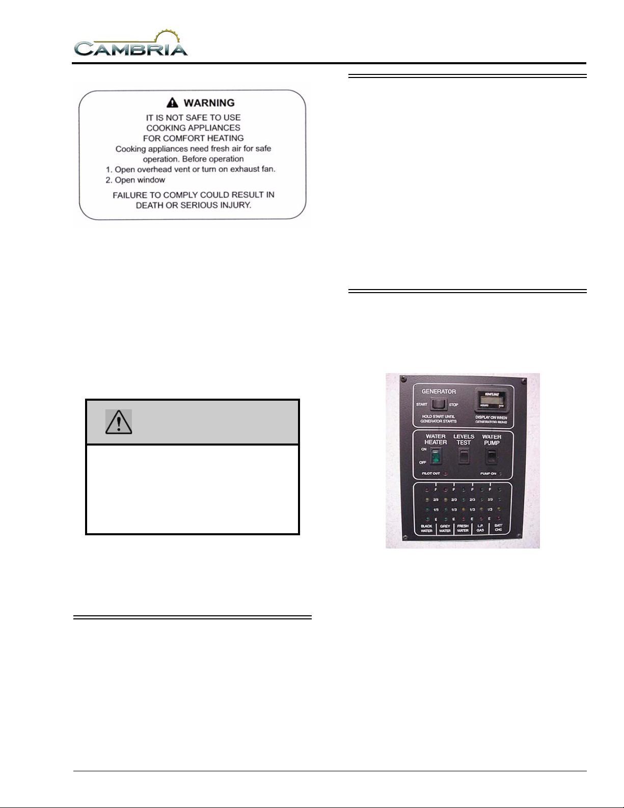
Unlike homes, the amount of oxygen supply is
limited due to the size of the recreational vehicle,
and proper ventilation when using the cooking
appliances avoids dangers of asphyxiation.
It is especially important that cooking
appliances not be used for comfort heating, as the
danger of asphyxiation is greater when the
appliance is used for long periods of time.
FAILURE TO COMPLY COULD RESULT
IN DEATH OR SERIOUS INJURY.
SECTION 4
APPLIANCES & SYSTEMS
RANGE HOOD
The range hood vent draws cooking odors and
airborne grease particles into the filtration grid
and recirculates the air or vents it to the outside of
the coach.
A light on the underside of the hood provides
illumination for cooking and food preparation.
Further Information
See the manufacturer’s information provided
in your InfoCase for instructions on replacement
of light bulbs and replacement or cleaning of
grease filter elements.
SYSTEMS MONITOR PANEL
The Systems Monitor Panel provides a
convenient central location for checking the
condition of all utility systems in your coach.
WARNING
Portable fuel-burning equipment
including wood and charcoal grills and
stoves, shall not be used inside the
recreational vehicle. The use of this
equipment inside the recreational vehicle
can cause fires or asphyxiation.
Further Information
See USING THE COOKTOP in the appliance
manufacturer’s RV Cooking Appliance Use and
Care guide in your InfoCase.
MICROWAVE OVEN
Refer to the microwave oven manufacturer’s
information provided in your InfoCase for
complete operating instructions.
At the touch of a button this panel will display
the fresh water and holding tank levels, propane
gas tank level, plus the house battery condition.
You can start the generator or turn on the water
pump and water heater. Indicator lights tell you if
the water pump is on or if the water heater pilot
light is out.
Water And Holding Tank Levels
Press and Hold the “Levels Test” switch to
show approximate level on the monitor lights.
4-3
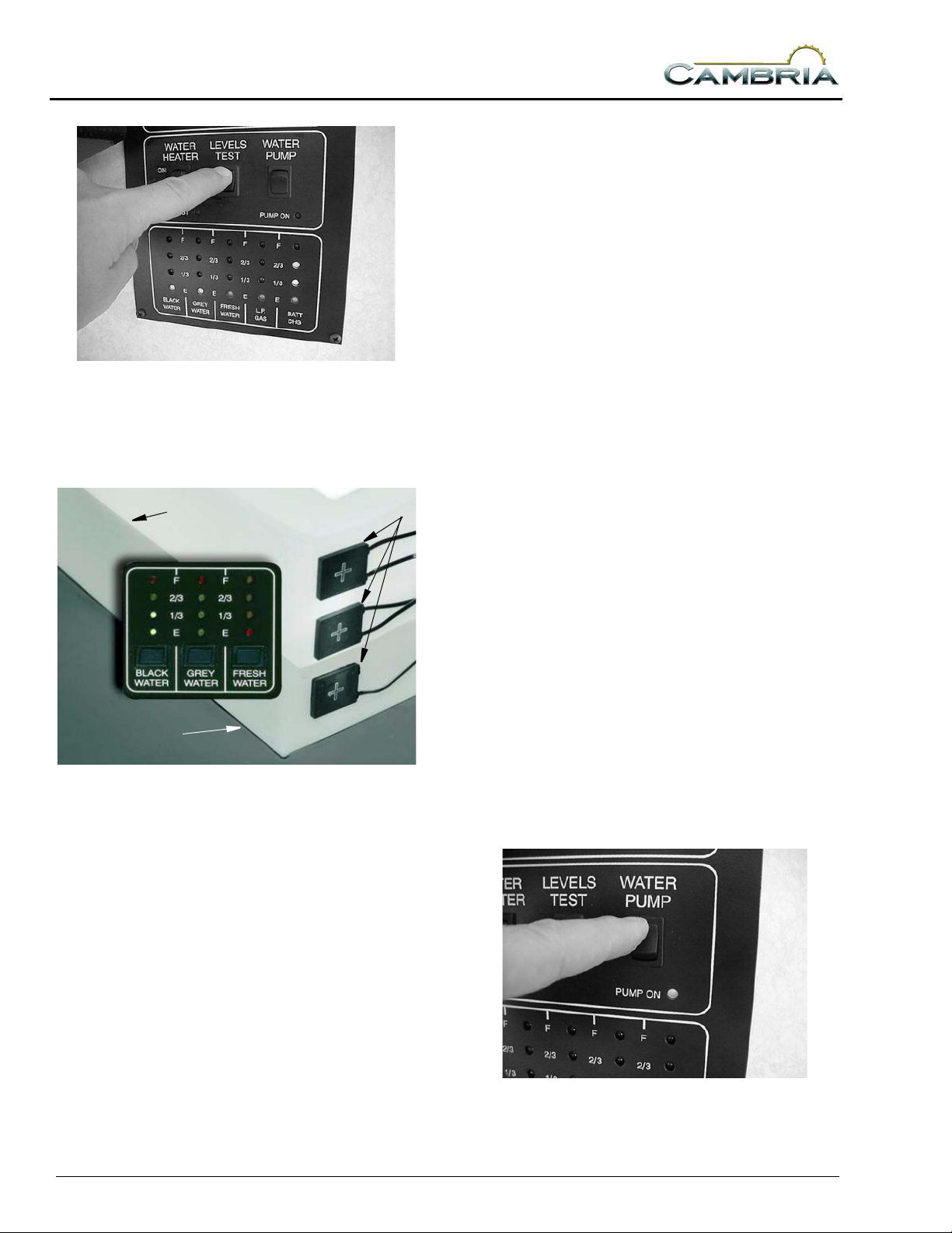
SECTION 4
APPLIANCES & SYSTEMS
The propane level is registered by a sending
unit on the tank. The gauge mounted on the side
of the tank will give a more accurate indication of
actual tank level if needed.
Battery Charge Meter
Press and Hold the “Levels Test” switch to
check the level of charge (voltage) in the 12-volt
house battery.
The colored segments (red, yellow and green)
will light from the bottom up to the amount of
charge the battery contains.
The approximate fluid levels are measured by
electronic sensors on the sides of the tanks. There
is generally more fluid in a tank than indicated on
the monitor panel.
Water Level
Water Tank
For example, if the fluid level is 1-2” below
the FULL sensor, the monitor will show the level
to be only 2/3 even though the tank is nearly full.
If a tank is about 1/4 full, the monitor will
register an empty tank because the fluid level is
below the 1/3 sensor even though there is still
fluid in the tank.
However, when the indicator reads FULL, the
tank is actually full.
Sensors
• Green - good or adequate charge.
• Yellow - marginal charge.
• Red - battery needs charging before use.
To get an accurate reading;
1. Both the chassis engine and the generator
engine must be shut off and 120 Volt AC
shoreline unplugged.
2. An interior light should be turned on to
provide a small load which draws off the
battery surface charge.
Water Pump Switch
When use of the self-contained water system
is desired, turn the “Water Pump” switch on. The
“Pump On” light will illuminate when the pump
switch is on and the system is operable. Water
will be available as soon as a faucet is opened.
Refer to “Water Pump” for additional
information on the water pump and initial startup.
Tank Capacities
See “Tank Capacities” in Introduction section.
Propane Gas Level
Press and Hold the “Levels Test” switch to
show approximate propane tank level.
4-4
(Some models may also have a pump switch in the
water system compartment on the outside of the
coach.)
 Loading...