

Winnebago Cambria 23D (2007), Cambria 26A (2007), Cambria 29H (2007) Owner's Manual

Table of Contents
INTRODUCTION 1
About This Manual ........................................................................................................................... 1-1
Safety Messages Used In This Manual ............................................................................................. 1-1
Owner InfoCase ................................................................................................................................ 1-2
Chassis Operating Guide .................................................................................................................. 1-2
Pre-Delivery Inspection .................................................................................................................... 1-2
Front Axle Tire Alignment ............................................................................................................... 1-2
Service and Assistance ...................................................................................................................... 1-2
Reporting Safety Defects .................................................................................................................. 1-2
Vehicle Certification Label ............................................................................................................... 1-3
Body and Chassis Specifications ...................................................................................................... 1-4
Tank Capacities ................................................................................................................................. 1-5
Owner Information ........................................................................................................................... 1-6
Emergency Information .................................................................................................................... 1-6
2006 New Vehicle Limited Warranty ............................................................................................... 1-7
SAFETY / PRECAUTIONS 2
General Warnings ............................................................................................................................. 2-1
Driving .............................................................................................................................................. 2-1
Formaldehyde Information ............................................................................................................... 2-1
LP Gas Leak Detector ....................................................................................................................... 2-1
Carbon Monoxide Warning .............................................................................................................. 2-2
Carbon Monoxide Alarm .................................................................................................................. 2-2
Smoke Alarm .................................................................................................................................... 2-3
Fire Extinguisher ............................................................................................................................... 2-3
Emergency Exits ............................................................................................................................... 2-4
Roadside Emergency ........................................................................................................................ 2-4
Jump Starting .................................................................................................................................... 2-5
Engine Overheat ............................................................................................................................... 2-5
Effects of Prolonged Occupancy ...................................................................................................... 2-6
5 - DASH / AUTO
DRIVING YOUR MOTOR HOME 3
Seats .................................................................................................................................................. 3-1
Seat Belts .......................................................................................................................................... 3-1
Child Restraints ................................................................................................................................. 3-2
Keyless Entry .................................................................................................................................... 3-2
Mirrors- Exterior ............................................................................................................................... 3-2
Rearview Monitor System ................................................................................................................ 3-3
Battery Boost Switch ........................................................................................................................ 3-3
In-Dash Radio ................................................................................................................................... 3-3
Rev. 0612060925 September 2006 Part No. 132000-27-006
Copyright 2006 Winnebago Industries, Inc. All rights reserved.

Table of Contents
Engine Access ................................................................................................................................... 3-4
Engine Cooling System .................................................................................................................... 3-4
Tires .................................................................................................................................................. 3-4
Suspension Alignment And Tire Balance ......................................................................................... 3-5
Rear Air Helper Springs ................................................................................................................... 3-5
Lights ................................................................................................................................................ 3-5
Automotive 12-Volt Fuses and Circuit Breakers .............................................................................. 3-6
Loading the vehicle ........................................................................................................................... 3-6
Roof Loading .................................................................................................................................... 3-6
Weighing Your Loaded Vehicle ....................................................................................................... 3-6
Car or Trailer Towing ....................................................................................................................... 3-8
Trailer Wiring Connector .................................................................................................................. 3-9
Towing Guidelines ............................................................................................................................ 3-9
Mountain Driving ........................................................................................................................... 3-10
Tools & Ladder Storage .................................................................................................................. 3-10
Storage Compartment Doors .......................................................................................................... 3-11
APPLIANCES & SYSTEMS 4
Refrigerator ....................................................................................................................................... 4-1
Refrigerator Service Access Compartment ....................................................................................... 4-1
Range Top ......................................................................................................................................... 4-2
Range and Oven ................................................................................................................................ 4-2
Microwave Oven ............................................................................................................................... 4-2
Range Hood ...................................................................................................................................... 4-2
Systems Monitor Panel ..................................................................................................................... 4-3
LP Gas Furnace ................................................................................................................................. 4-4
Heat Pump ......................................................................................................................................... 4-5
Ducted Roof Air Conditioning System ............................................................................................. 4-5
Thermostat Operation ....................................................................................................................... 4-6
Water Heater ..................................................................................................................................... 4-7
Pressure-Temperature Relief Valve .................................................................................................. 4-7
Water Heater By-Pass Valve ............................................................................................................ 4-8
Manual Entrance Step ....................................................................................................................... 4-8
Electric Entrance Step ....................................................................................................................... 4-9
Windows ........................................................................................................................................... 4-9
LP GAS 5
LP Gas Supply .................................................................................................................................. 5-1
Safe Use of the LP Gas System ........................................................................................................ 5-2
LP Gas Warnings and Precautions .................................................................................................... 5-3
Pressure Regulator ............................................................................................................................ 5-4
ELECTRICAL 6
Electrical Cautions ............................................................................................................................ 6-1
110-Volt AC System ......................................................................................................................... 6-1
External Power Cord (Shoreline) ...................................................................................................... 6-1

Table of Contents
Power Center ..................................................................................................................................... 6-2
110-Volt Circuit Breakers ................................................................................................................. 6-3
110-Volt Receptacles (Outlets) ......................................................................................................... 6-3
Ground Fault Circuit Interrupter ....................................................................................................... 6-3
Auxiliary 110-Volt Generator ........................................................................................................... 6-4
12-Volt DC System ........................................................................................................................... 6-5
Auxiliary Battery (AUX BATT) Switch .......................................................................................... 6-6
House Battery Access ....................................................................................................................... 6-6
Battery Care ...................................................................................................................................... 6-6
12-Volt House Fuses and Circuit Breakers .......................................................................................6-8
PLUMBING 7
Fresh Water System .......................................................................................................................... 7-1
Water Pump ...................................................................................................................................... 7-2
Disinfecting Fresh Water Systems on RVs ....................................................................................... 7-3
Shower Hose Vacuum Breaker ......................................................................................................... 7-4
Exterior Shower / Wash Station ........................................................................................................ 7-4
Toilet ................................................................................................................................................. 7-4
Waste Water System ......................................................................................................................... 7-5
Water System Drain Valve Locations .............................................................................................. 7-7
Winterizing Procedure ...................................................................................................................... 7-9
ENTERTAINMENT 8
DVD Player ....................................................................................................................................... 8-1
12-Volt Deluxe Sound System ......................................................................................................... 8-1
DC-AC Electrical Voltage Inverter - 300 Watt ................................................................................ 8-1
TV Antenna ....................................................................................................................................... 8-2
TV Signal Amplifier ......................................................................................................................... 8-2
Cable TV Hook-Up ........................................................................................................................... 8-3
Digital Satellite Television System ................................................................................................... 8-3
In Motion Satellite Dish Antenna Switch ......................................................................................... 8-4
Exterior Entertainment Center .......................................................................................................... 8-4
Two-Way Radios .............................................................................................................................. 8-5
FURNITURE & SOFTGOODS 9
Swivel Glider Lounge Chair ............................................................................................................. 9-1
Sleeping Facilities ............................................................................................................................. 9-1
Day/ Nighter Pleated Blinds ............................................................................................................. 9-4
Quartz Wall Clock ............................................................................................................................ 9-4
Wood Furniture and Cabinetry ......................................................................................................... 9-5
SLIDEOUT / LEVELING 10
Slideout Room Operation ............................................................................................................... 10-1
Slideout Room Emergency Retraction ........................................................................................... 10-3
General Slideout Care ..................................................................................................................... 10-4

Table of Contents
MAINTENANCE/STORAGE 11
Sealants ........................................................................................................................................... 11-1
Roof ................................................................................................................................................ 11-1
Underbody ...................................................................................................................................... 11-1
Exterior Finish ................................................................................................................................ 11-2
Care of Stripes and Decals .............................................................................................................. 11-2
Plastic Parts - Cleaning ................................................................................................................... 11-2
Exterior Lights ................................................................................................................................ 11-3
Interior Soft Goods ......................................................................................................................... 11-3
Care Of Ceiling Fabric .................................................................................................................... 11-5
Cabinetry ......................................................................................................................................... 11-6
Vinyl Wallboard ............................................................................................................................. 11-6
Tables and Countertops .................................................................................................................. 11-6
Galley Sink ..................................................................................................................................... 11-6
Range and Refrigerator ................................................................................................................... 11-7
Bathroom ........................................................................................................................................ 11-7
Doors and Windows ........................................................................................................................ 11-7
Day/ Nighter Pleated Blinds ........................................................................................................... 11-7
Preparing Vehicle For Storage ........................................................................................................ 11-7
Removal From Storage ................................................................................................................... 11-8
Coach Maintenance Chart ............................................................................................................. 11-10
Recommended Sealant Application .............................................................................................. 11-13
SECTION 1 INTRODUCTION
Congratulations! We welcome you to the
exciting world of motor home travel and
camping. You will find it convenient and
enjoyable to have all the comforts of home and
still enjoy the great outdoors wherever you
choose to go.
Your motor home has been carefully
designed, engineered and manufactured to
provide dependability as well as safety. Before
sliding into the driver’s seat, please become
familiar with operations and features. This
manual was prepared to aid you in the proper care
and operation of the vehicle and equipment. We
urge you to read it completely. In addition, spend
some time with the dealer when you take
delivery; you will want to learn all you can about
your new motor home.
ABOUT THIS MANUAL
Please read this operator’s manual completely
to understand how everything in your coach
works before taking it on its “maiden voyage.”
NOTE: This manual describes many features of
your motor home and includes
instructions for its safe use. This manual,
including photographs and illustrations,
is of a general nature only. Some
equipment and features described or
shown in this manual may be optional
or unavailable on your model. Because
of Winnebago Industries’ continuous
program of product improvement, it is
possible that recent product changes and
information may not be included. The
instructions included in this manual are
intended as a guide, and in no way
extend the responsibilities of Winnebago
Industries beyond the standard written
warranty as presented in this manual.
The descriptions, illustrations, and
specifications in this manual were
correct at the time of printing. We reserve
the right to change specifications or
design without notice, and without
incurring obligation to install the same
on products previously manufactured.
SAFETY MESSAGES USED IN THIS MANUAL
Throughout this manual, certain items are
labeled Danger, Warning, Caution or Note.
These terms alert you to precautions that may
involve damage to your vehicle or a risk to your
personal safety. Read and follow them carefully.
DANGER
DANGER indicates a directly hazardous
situation which, if not avoided, will result
in death or serious personal injury.
WARNING
WARNING indicates a potentially
hazardous situation which, if not avoided,
could result in death or serious personal
injury.
5 - DASH / AUTO
CAUTION
CAUTION indicates a potentially
hazardous situation which, if not avoided,
could result in damage mainly to
equipment or property, but in some cases
may also result in minor or moderate
personal injury.
NOTE: A ‘Note’ is not necessarily safety related
but indicates a recommendation or
special point of information that could
assist in understanding the use or care of
a feature item.
1-1

SECTION 1
INTRODUCTION
OWNER INFOCASE
The materials in your Owner InfoCase contain
warranty information and operating and
maintenance instructions for the various
appliances and components in your motor home.
NOTE: Many of the instruction sheets and
manuals for the various appliances and
components have been incorporated into
the Operator Manual Supplement for
your convenience. Throughout the
Operator’s manual when referred to the
InfoCase keep in mind that much of this
information will be found in the Operator
Manual Supplement. Please read the
FAQ in section 1 of the Operator Manual
Supplement for more details.
CHASSIS OPERATING GUIDE
Throughout this manual, frequent reference is
made to the vehicle chassis operating guide. The
chassis guide is the operator’s manual provided
by the manufacturer of the chassis on which this
motor home is built (e.g., Workhorse or Ford).
Consult the chassis guide for operating safety and
maintenance instructions pertaining to the
chassis section of the motor home.
PRE-DELIVERY INSPECTION
This motor home has been thoroughly
inspected before shipment. Your dealer is
responsible for performing a complete predelivery inspection of the chassis and all motor
home components.
As a part of the pre-delivery inspection
procedure, the dealer is responsible for road
testing the motor home; noting and correcting
any problems before delivery.
FRONT AXLE TIRE ALIGNMENT
We recommend that you have the front
suspension and steering alignment checked and
adjusted after you have fully loaded the vehicle
according to your needs. Thereafter, have
alignment inspected periodically to maintain
vehicle steering performance and prevent uneven
tire wear.
SERVICE AND ASSISTANCE
Your dealer will be glad to provide any
additional information you need, as well as
answer any questions you might have about
operating the equipment in your motor home.
When it comes to service, remember that your
dealer knows your vehicle best and is interested
in your satisfaction. Your dealer will provide
quality maintenance and any other assistance that
you may require during your ownership of this
vehicle.
If you need warranty repairs while traveling
you may take your motor home to any authorized
Winnebago or Itasca dealership and request their
assistance.
See the dealership directory in your Owner
InfoCase.
REPORTING SAFETY DEFECTS
If you believe that your vehicle has a defect
which could cause a crash or could cause injury
or death, you should immediately inform the
National Highway Traffic Safety Administration
(NHTSA) in addition to notifying Winnebago
Industries, Inc.
If NHTSA receives similar complaints, it may
open an investigation, and if it finds that a safety
defect exists in a group of vehicles, it may order
a recall and remedy campaign. However,
NHTSA cannot become involved in individual
problems between you, your dealer, or
Winnebago Industries.
To contact NHTSA, you may either call the
Auto Safety Hotline toll-free at 1-800-424-9393
(or 366-0123 in Washington, D.C. area) or write
to: NHTSA, U.S. Department of Transportation,
Washington, D.C. 20590. You can also obtain
other information about motor vehicle safety
from the Hotline.
1-2
SECTION 1
INTRODUCTION
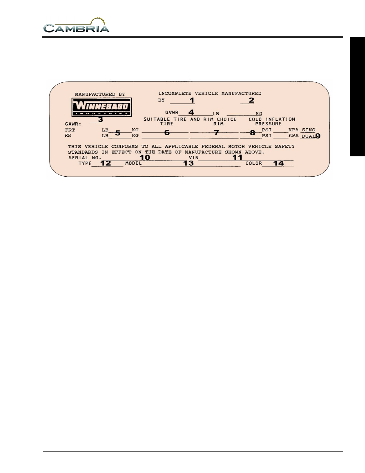
VEHICLE CERTIFICATION LABEL
This label contains vehicle identification and other important reference information.The label is affixed
to the armrest panel or wall to the left of the driver seat.
1 INTRODUCTION
Explanation of Data
1. Chassis manufacturer.
2. Chassis manufacture date.
3. Month and year of manufacture at Winnebago Industries.
4. Gross Vehicle Weight Rating: Total permissible weight of the vehicle, including driver, passengers, total cargo carried (including all liquids) and equipped with all options.
5. Gross Axle Weight Rating: Total permissible weight allowed for the front and rear axles (listed in pounds and kilograms).
6. Suitable Tire Choice: Tires recommended to meet handling and safety requirements. When replacing any of the tires on your vehicle, always replace with a tire that meets these specifications.
7. Suitable Rim Choice: Wheel rims recommended to meet handling and safety requirements. When replacing any of the rims on your vehicle, always replace with a rim that meets these specifications.
8. Cold Inflation Pressure: Inflation pressures at Gross Axle Weight Ratings recommended (while Cold) for the tires originally equipped on your vehicle. These pressure levels must be maintained to assure proper handling, safety and fuel economy.
9. Rear Axle Wheel Configuration: Single or Dual as it relates to the inflation.
10. Serial Number: This is the serial number assigned to the completed vehicle by Winnebago Industries.
11. Vehicle Identification Number (VIN): This
number identifies the chassis on which the
motor home is built. The 10th digit of the VIN
designates the chassis model year. (5=2005,
6=2006, etc.). This information is useful when
ordering chassis repair parts.
12. Type: States the NHTSA designated usage classification for your motor home. MPV signifies a Multi-purpose Passenger Vehicle.
13. Model: Lists the Winnebago product model number of your vehicle.
14. Color: Signifies the color code number of the decor used throughout the vehicle. This number is necessary for ordering replacement cushions, curtains, carpet, etc.
1-3

SECTION 1
INTRODUCTION
BODY AND CHASSIS SPECIFICATIONS
Model 23D 26A 29H
Length (Bumper to Bumper) 23’ 10” 26’ 9” 30’ 1”
Exterior Height (w/AC) 10’ 5”* 10’ 3”* 10’ 3”*
Exterior Width 7’ 11.2” 7’ 11.2” 7’ 11.2”
Exterior Storage (cu. ft.) 19.2 43.0 29.9
Interior Height 6’ 5” 6’ 5” 6’ 5”
Interior Width 7’ 8” 7’ 8” 7’ 8”
GCWR (lbs.) F350
F450
GVWR (lbs.) F350
F450
GAWR - Front (lbs.) F350
F450
GAWR - Rear (lbs.) F350
F450
Wheelbase 158” 182” 220”
18,500
20,000**
11,50 0
14,050**
4,600
4,600**
7,800
9,450**
n/a
20,000
n/a
14,050
n/a
4,600
n/a
9,450
n/a
20,000
n/a
14,050
n/a
4,600
n/a
9,450
*Add 1” if equipped with In-Motion satellite dish.
**Optional chassis for model 23D
NOTE: The height of each model is based on the curb weight of a typically equipped unit and is
measured to the highest standard feature on the roof. The actual height of a vehicle may vary by
several inches depending on equipment variations. Refer to Section 3 for Towing Guidelines.
1-4

SECTION 1
INTRODUCTION
TANK CAPACITIES
Chassis Fuel Tank
Model 23D . . . . . . . . . . . . . . . . . . . . . . . . . . . . . . . . . . . . . . . . . . . . . . . . . . . . . . . . . . . . . . . . . .55 gal.
Model 26A . . . . . . . . . . . . . . . . . . . . . . . . . . . . . . . . . . . . . . . . . . . . . . . . . . . . . . . . . . . . . . . . . .55 gal.
Model 29H . . . . . . . . . . . . . . . . . . . . . . . . . . . . . . . . . . . . . . . . . . . . . . . . . . . . . . . . . . . . . . . . . .55 gal.
LP Gas Tank
All Models . . . . . . . . . . . . . . . . . . . . . . . . . . . . . . . . . . . . . . . . . . . . . . . . . . . . . . .18 gal (*23 gal w.c.)
Fresh Water Tank
Model 23D . . . . . . . . . . . . . . . . . . . . . . . . . . . . . . . . . . . . . . . . . . . . . . . . . . . . . . . . . . . . . . . . . .27 gal.
Model 26A . . . . . . . . . . . . . . . . . . . . . . . . . . . . . . . . . . . . . . . . . . . . . . . . . . . . . . . . . . . . . . . . . .37 gal.
Model 29H . . . . . . . . . . . . . . . . . . . . . . . . . . . . . . . . . . . . . . . . . . . . . . . . . . . . . . . . . . . . . . . . . .33 gal.
Water Heater
All Models. . . . . . . . . . . . . . . . . . . . . . . . . . . . . . . . . . . . . . . . . . . . . . . . . . . . . . . . . . . . . . . . . . . . 6 gal
HT1-Black Water Holding Tank
Model 23D (Toilet) . . . . . . . . . . . . . . . . . . . . . . . . . . . . . . . . . . . . . . . . . . . . . . . . . . . . . . . . . . . .23 gal.
Model 26A (Toilet) . . . . . . . . . . . . . . . . . . . . . . . . . . . . . . . . . . . . . . . . . . . . . . . . . . . . . . . . . . . .32 gal.
Model 29H (Toilet) . . . . . . . . . . . . . . . . . . . . . . . . . . . . . . . . . . . . . . . . . . . . . . . . . . . . . . . . . . . .36 gal.
HT2-Gray Water Holding Tank
Model 23D (Galley, Shower & Lavatory). . . . . . . . . . . . . . . . . . . . . . . . . . . . . . . . . . . . . . . . . . 30 gal.
Model 26A (Galley, Shower & Lavatory). . . . . . . . . . . . . . . . . . . . . . . . . . . . . . . . . . . . . . . . . . .37 gal.
Model 29H (Galley, Shower & Lavatory). . . . . . . . . . . . . . . . . . . . . . . . . . . . . . . . . . . . . . . . . . .30 gal.
*LP Gas tank capacity shown is the usable “full” LP gas capacity, which is 80% of the tank
manufacturer’s listed water capacity (w.c. shown in parenthesis). An LP tank must have at least 20% of
tank volume free to allow for expansion and proper vaporization of the liquid fuel. The tank is also
equipped with mandatory safety shut-off equipment that prevents filling above this level.
1 INTRODUCTION
NOTE: Capacities shown are approximate volumes based on computer design calculations. Usable
capacities may vary according to fabrication and installation of tanks and compartments.
1-5

SECTION 1
INTRODUCTION
OWNER INFORMATION
Owner’s Name _______________________________________________________________________
Street Address ________________________________________________________________________
City and State (or Province in Canada)_____________________________________________________
Motor Home Serial Number _____________________________________________________________
Vehicle Chassis Identification No (VIN) ___________________________________________________
Vehicle Mileage at Time of Delivery ______________________________________________________
Selling Dealer Name and Address ________________________________________________________
___________________________________________________________________________________
EMERGENCY INFORMATION
YOUR WINNEBAGO INDUSTRIES DEALER
Name_______________________________________________________________________________
Address _____________________________________________________________________________
___________________________________________________________________________________
Contact Person _______________________________________________________________________
Phone ______________________________________________________________________________
CHASSIS DEALER/SERVICE CENTER
Name_______________________________________________________________________________
Address _____________________________________________________________________________
___________________________________________________________________________________
Contact Person _______________________________________________________________________
Phone ______________________________________________________________________________
INSURANCE POLICY
Company____________________________________________________________________________
Policy Number _______________________________________________________________________
Phone ______________________________________________________________________________
1-6

2006 NEW VEHICLE LIMITED WARRANTY
WINNEBAGO INDUSTRIES, INC.
SECTION 1
INTRODUCTION
WARRANTY COVERAGE TO OWNER
Winnebago Industries, Inc. of Forest City, Iowa warrants each new
Winnebago Industries motor home to the owner for use in the U.S.A.
and Canada as follows:
WARRANTY PERIOD
The Warranty Period for all coverages begins on the date the vehicle
is delivered to the first retail purchaser or first placed in service as a
demonstrator or company vehicle.
BASIC COVERAGE
The basic Warranty Period is 12 months or 15,000 miles (24,135
kilometers), on the odometer, whichever occurs first. This is the only
warranty authorized by Winnebago. There are no other promises,
representations or warranties concerning the matters set forth herein.
Winnebago Industries does not authorize any person to create for it
any other obligations or liability in connection with this vehicle. ANY
IMPLIED WARRANTY OF MERCHANTABILITY OR FITNESS FOR
A PARTICULAR PURPOSE APPLICABLE TO THIS VEHICLE IS
LIMITED IN DURATION TO THE DURATION OF THIS WRITTEN
WARRANTY AS HEREINBEFORE OR HEREINAFTER PROVIDED.
THE PERFORMANCE OF REPAIRS IS THE EXCLUSIVE REMEDY
UNDER THIS WRITTEN WARRANTY OR ANY IMPLIED
WARRANTY. WINNEBAGO INDUSTRIES SHALL NOT BE LIABLE
FOR INCIDENTAL OR CONSEQUENTIAL DAMAGES FOR LOSS
OF TIME, INCONVENIENCE, OR OTHER CONSEQUENTIAL
DAMAGE INCLUDING EXPENSE FOR GASOLINE, TELEPHONE,
TRAVEL, LODGING, LOSS OR DAMAGE TO PERSONAL
PROPERTY, OR LOSS OF REVENUE RESULTING FROM
BREACH OF THIS WRITTEN WARRANTY OR ANY IMPLIED
WARRANTY. Some states do not allow limitations on how long an
implied warranty will last or the exclusion or limitation of incidental or
consequential damages, so the above limitations or exclusions may
not apply to you.
ITEMS NOT SUBJECT TO WARRANTY COVERAGE.
Chassis, Drivetrain and related components*
Wheels*
Tires*
Service Items, such as Windshield Wiper Blades, Lubricants, Fluids
& Filters
Adjustments
*These items are covered under the manufacturer’s individual
warranty.
This warranty gives you specific legal rights and you may also have
other rights which vary from state to state.
Also, this warranty shall not apply to failures, damage or
malfunctions resulting from normal wear, misuse, abuse, negligence,
alteration, accident, fire, improper repair of the vehicle or failure to
follow recommended maintenance requirements.
36 MONTHS/36,000 MILE STRUCTURAL WARRANTY
At the expiration of the Basic Coverage and for the remainder of the
period of 36 months or 36,000 miles (57,924 kilometers), on the
odometer, whichever occurs first, Winnebago Industries warrants the
following:
1. Structural defects of the subfloor, floor, and slide-out room
assembly. Floor lamination failure and lamination failure of the
subfloor panels and risers are covered by the structural
warranty.
2. Body Thermo-Panel
against delamination. Body Thermo-Panel
bonding of the exterior skin and the interior paneling to an
insulating core material. Delamination (separation of layers)
Lamination of the sidewalls and backwall
Lamination is the
caused by other factors such as physical damage or failure to
properly maintain sealants is not covered by this warranty.
WINNEBAGO INDUSTRIES’ RESPONSIBILITY
Any part of the vehicle subject to warranty which is found to be
defective in material or workmanship, will be repaired or replaced at
Winnebago Industries’ option upon notice of the defect without
charge to the customer for parts or labor. While any Winnebago
Industries motor home dealer can perform warranty service, we
recommend you return to the dealership that sold you your vehicle. If
you are touring or have moved, contact any Winnebago Industries
motor home dealer in the United States or Canada for warranty
service.
CUSTOMER RESPONSIBILITY WHEN REPAIRS ARE NEEDED
If a part of the system covered by this warranty fails to function or
requires service during the warranty period:
1. Promptly take the vehicle to the selling dealer for repair or
inspection.
2. Written notice of defects must be given to the selling dealer or
manufacturer no later than 10 days after the expiration of the
warranty.
3. If the dealer is incapable of making the repairs, request that he
contact Winnebago Industries, Inc.
4. If, after the above steps are completed and the repair is not
made, the customer should contact Winnebago Industries, Inc.,
P.O. Box 152, Forest City, Iowa 50436, Attention: Owner
Relations Department (800-537-1885) and furnish the following
information:
The complete serial number of the vehicle
Date of retail purchase
Selling dealer’s name
Nature of the service problem, and a brief explanation of the
steps or service the dealer has performed, and the results
obtained. The customer may be directed to another dealer
or service center for repairs to be completed, if such a
dealer or service center is better able to complete the
repair.
Winnebago Industries may, at its option, request the vehicle be
returned to Forest City, Iowa for repair. If the customer refuses to
allow repairs to be performed at the Forest City, Iowa facility, the
warranty on that repair will be voided.
5. If after the above steps are completed and the repairs are not
satisfactory, the customer may contact the Service
Administration Manager of Winnebago Industries, and request a
customer relations board meeting to resolve the problem. This
action, however, is not mandatory.
6. Certain components are covered beyond the 12 months/15,000
miles basic warranty coverage by the individual manufacturer’s
warranty. Please refer to the component’s information supplied
in the owner’s information InfoCase for any additional warranty
coverage after the basic warranty has expired.
DEALER’S REPRESENTATIONS EXCLUDED
Winnebago Industries, Inc. does not undertake the responsibility to
any purchaser of its products for any undertaking, representation, or
warranty made by dealers selling its product beyond those herein
expressed.
INSTALLATION NOT COVERED
Winnebago Industries, Inc. cannot , however, and does not accept
any responsibility in connection with any of its motor homes for
additional equipment or accessories installed at any dealership or
other place of business, or by any other party other than Winnebago
Industries, Inc. Such installation of equipment or accessories by any
other party will not be covered by the terms of this warranty.
1 INTRODUCTION
1-7

SECTION 1
INTRODUCTION
CARE AND MAINTENANCE
It is the owner’s responsibility to perform the care, maintenance and
proper load distribution described in the owner’s manual which
accompanies your motor home. Any damage which results to your
vehicle as a result of your failure to perform such duties, is not
covered.
Damage to appearance items such as fiberglass, metal, paint,
fabrics and trim, may occur during manufacturing or transporting.
Normally, any factory defect or damage is corrected at the factory. In
addition, dealers are obligated to inspect each vehicle upon delivery
to them and prior to delivery to you. You should also immediately
inspect appearance items and advise your selling dealer of any
discrepancies. Damage and normal deterioration due to use and
exposure is not covered by this warranty.
CHANGES IN DESIGN
Winnebago Industries, Inc. reserves the right to make changes in
design and changes or improvements upon its products without
imposing any obligation upon itself to install the same upon its
products theretofore manufactured.
NEW YORK:
If your motor home has been repaired three or more times for the
same nonconformity, defect, or condition, or if your motor home has
been out of service by reason of repair for twenty-one days, Section
198-a of the General Business Law of the State of New York requires
you to provide written notice by certified mail, return receipt
requested, to Winnebago Industries or its authorized dealer before
making any claim under that section of the law. If you do have
problems with your motor home, you should provide written notice to
Winnebago Industries at the following address:
Winnebago Industries, Inc.
P.O. Box 152
Forest City, Iowa 50436
Atten: Owner Relations
CALIFORNIA:
Winnebago Industries participates in the Consumer Arbitration
Program for Recreation Vehicles (CAP-RV). This third-party dispute
resolution program is available, at no charge to you, to settle
unresolved warranty disputes for recreational vehicles. This dispute
resolution program reviews eligible product and service related
complaints involving warranty covered components.
To find out more about the program, or to request an
application/brochure, please call the Arbitration Administration office
toll-free 800-279-5343.
The CAP-RV program operates as a certified mechanism under the
review of the California Arbitration Certification Program. You must
utilize the arbitration program before claiming rights conferred by 15
USC section 2310 (Uniform Commercial Code) or Civil Code section
1793.22(b) (Tanner Consumer Protection Act). You are not required
to use the program if you choose to seek redress by pursuing rights
and remedies not created by those laws.
1-8
Revised 9-05
SECTION 2 SAFETY / PRECAUTIONS
GENERAL WARNINGS
• Only seats equipped with seat belts are to be
occupied while the vehicle is moving.
• Make sure all passengers have seat belts
fastened in a low and snug position so the
force exerted by the belt in a collision will be
spread across the strong hip area. Pregnant
women should wear a lap-shoulder belt
whenever possible, with the lap belt portion
worn low and snug throughout the pregnancy.
• All moveable or swiveling seats should be
placed and locked in forward facing positions
while the vehicle is moving.
• Never let passengers stand or kneel on seats
while the vehicle is moving.
• Sleeping facilities are not to be utilized while
vehicle is moving.
• Examine the escape window and be familiar
with its operation.
• Ιnspect the fire extinguisher monthly for
proper charge and operating condition. This
should also be done before beginning a
vacation or any extended trip.
DRIVING
not been affected. Never operate any vehicle if
a difference in braking efficiency is
noticeable.
• Adverse weather conditions and extremes in
terrain may affect handling and/or
performance of your vehicle. Refer to your
chassis manual for related information.
FORMALDEHYDE INFORMATION
WARNING
Some components in this vehicle contain
formaldehyde based adhesives which
may release formaldehyde fumes into the
air for an unknown period of time until total
dissipation occurs. Individuals who are
allergic to formaldehyde gas fumes may
experience irritation to eyes, ears, nose
and throat. Reaction in infants may be
more severe. Although long range effects
are not well understood, testing to date
has not revealed any serious health
effects in humans at the level of emission
from these products.
• Do not attempt to adjust the driver’s seat while
the vehicle is moving.
• Do not adjust tilt steering in a moving vehicle.
• Do not operate the cruise control on icy or
extremely wet roads, winding roads, in heavy
traffic, or in any other traffic situation where
a constant speed cannot be maintained.
• Use care when accelerating or decelerating on
a slippery surface. Abrupt speed changes can
cause skidding and loss of control.
• Driving through water deep enough to wet the
brakes may affect stopping distance or cause
the vehicle to pull to one side. Check brake
operation in a safe area to be sure they have
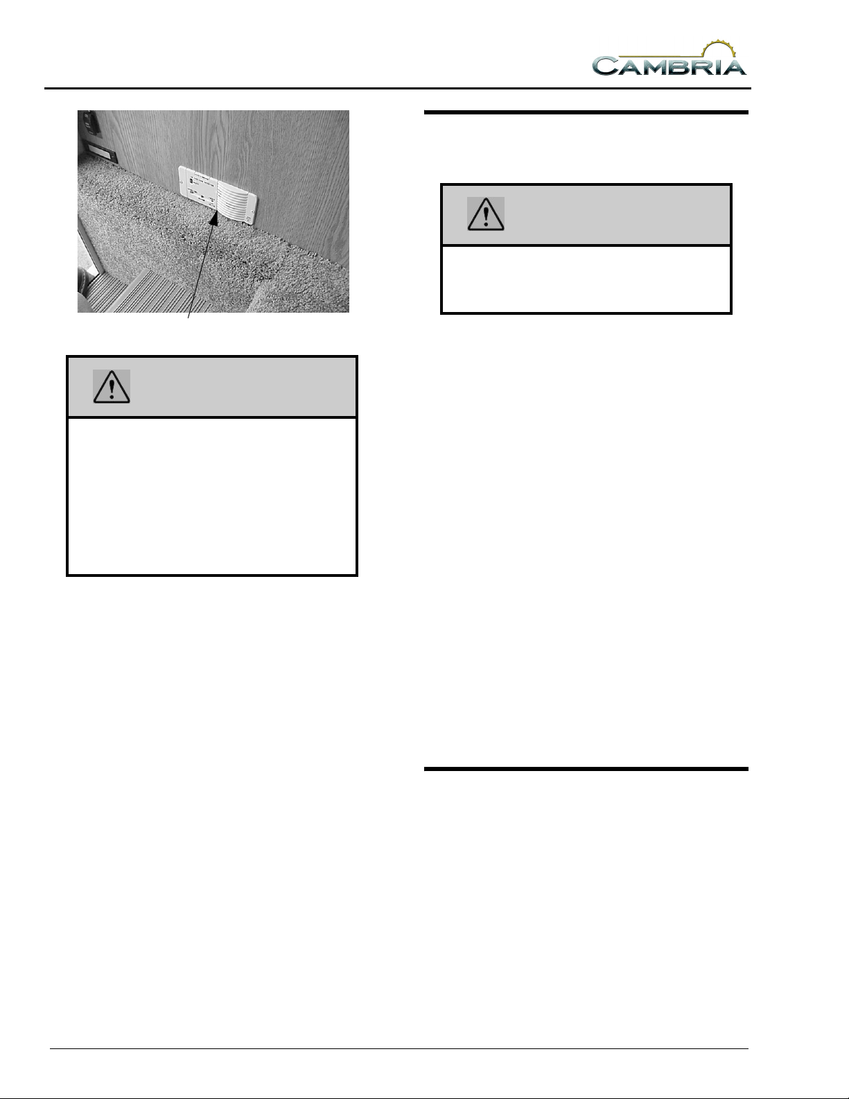
LP GAS LEAK DETECTOR
5 - DASH / AUTO
Your coach is equipped with an LP gas leak
detector which sounds an alarm if an unsafe
amount of LP gas is present inside the coach.
Because LP gas is heavier than air, the leak
detector is located on a cabinet face near the floor
of the coach.
2-1
SECTION 2
SAFETY / PRECAUTIONS
CARBON MONOXIDE WARNING
WARNING
Avoid inhaling exhaust gases, as they
contain carbon monoxide, which is a
colorless, odorless and poisonous gas.
LP Gas Leak Detector
WARNING
Never use an open flame to test for gas
leaks. When testing for gas line leaks with
a soapy water solution, DO NOT use a
detergent containing ammonia or
chlorine. These substances may
generate a chemical reaction causing
corrosion to gas lines, resulting in
dangerous leak conditions.
Power Connection
The LP gas leak detector is powered by the
coach batteries. If the auxiliary battery switch is
shut off or the battery cable is disconnected from
the batteries, the alarm will not work. The LP gas
leak detector fuse is located in the 12-volt house
electrical load center.
Because the LP gas leak detector is connected
to the auxiliary battery, it is always drawing a
small amount of current. Even though this current
draw is slight, it could drain the coach battery
during storage periods when the house battery
will not be charged regularly by the engine or
shoreline. Turn the Aux. Batt switch OFF to
avoid current drain during storage periods.
Further Information
See the manufacturer’s information in your
Owner InfoCase for further instructions on
nuisance alarms and care and testing of the LP
gas leak detector.
The best protection against carbon monoxide
entry into the vehicle body is a properly
maintained engine exhaust and ventilation
system. It is recommended that the exhaust
system and body be inspected by a qualified
motor home service center.
• Each time the vehicle is serviced for an oil
change.
• Whenever a change in the sound of the
exhaust system is noticed.
• Whenever the exhaust system, underbody or
rear of the vehicle is damaged.
To allow proper operation of the vehicle’s
ventilation system, keep front ventilation inlet
grill clear of snow, leaves or other obstructions at
all times. DO NOT OCCUPY A PARKED
VEHICLE WITH ENGINE RUNNING FOR
AN EXTENDED PERIOD.
Do not run engine in confined areas, such as a
garage, except to move vehicle into or out of the
area.
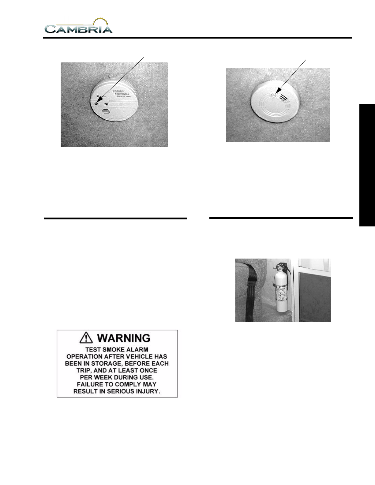
CARBON MONOXIDE ALARM
Your coach is equipped with a carbon
monoxide (CO) alarm located on the ceiling in
the bedroom area. The CO alarm is powered by a
9-volt battery and has a sensor that is designed to
detect toxic carbon monoxide gas fumes
resulting from incomplete combustion of fuel. It
will detect CO gas from any combustion source
such as the furnace, gas range/oven, water heater,
refrigerator, chassis engine, and electric
generator engine.
2-2
SECTION 2
SAFETY / PRECAUTIONS
Press button to test
Carbon Monoxide Alarm
Further Information
Please read the information provided by the
manufacturer, which is included in your Owner
InfoCase. It includes information on precautions,
operational testing, and battery replacement.
SMOKE ALARM
Press button to test
Smoke Alarm
Further Information
See the manufacturer’s information in your
Owner InfoCase for further instructions on
battery replacement and testing of the smoke
alarm.
2 SAFETY / PRECAUTIONS
FIRE EXTINGUISHER
Your motor home is equipped with a smoke
alarm located on the ceiling in the galley area.
The smoke alarm is powered by a 9-volt battery
and has a sensor that is designed to detect smoke.
This alarm meets U.L. Standard 217 and NFPA
Standard 74 for operation of smoke detection
devices.
The following label is affixed either to the
smoke alarm or on the ceiling near the smoke
alarm.
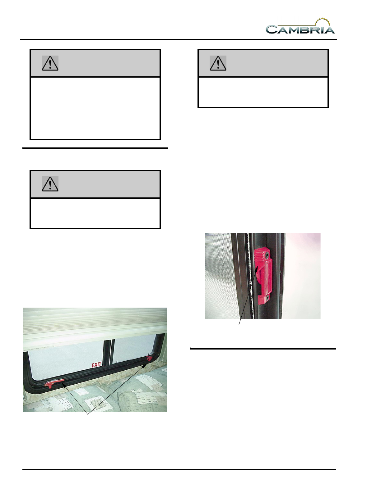
A dry chemical fire extinguisher is located
near the main entrance door.
We recommend that you become thoroughly
familiar with the operating instructions displayed
on the side of the fire extinguisher or in the
information supplied in your Owner InfoCase.
We also recommend that you inspect the fire
extinguisher for proper charge at least once a
month in accordance with National Fire
Protection Association (NFPA)
recommendations as stated on the label.
If the charge is insufficient, the fire
extinguisher must be replaced.
2-3
SECTION 2
SAFETY / PRECAUTIONS
WARNING
Do not test the fire extinguisher by
discharging it. Partial discharge can
cause leakage of pressure or contents
which would render the unit inoperative
when needed. When using the fire
extinguisher, aim the spray at the base of
the fire.
EMERGENCY EXITS
WARNING
Use care when exiting emergency
window, as broken glass may be present
in the exit area.
Escape Window
The bedroom escape window is secured by
two red safety latches at the bottom of the
window.
To open, lift both latches up and toward the
center of the window, then push outward near the
bottom of the window.
WARNING
This window should be kept closed while
driving to avoid drawing dangerous
exhaust gases into the vehicle.
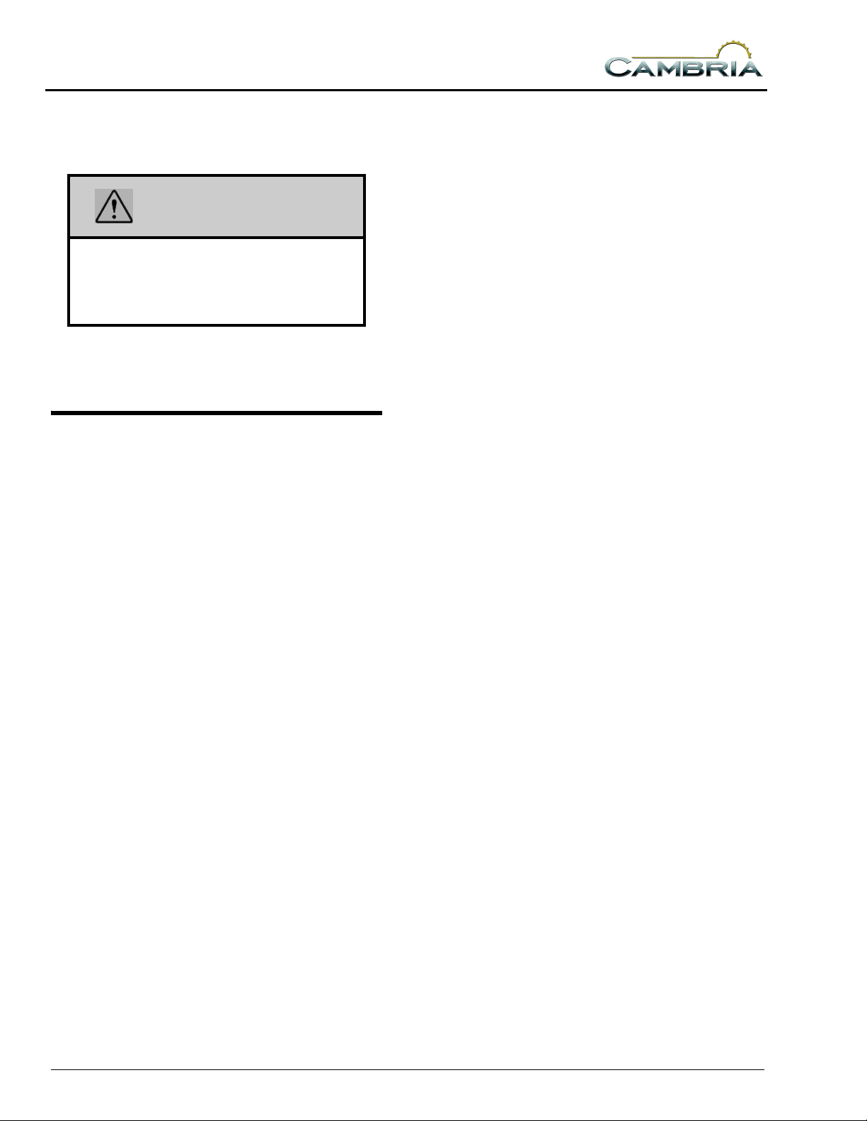
Using Slider Windows As Emergency Exits
Most slider windows along the side of the
motor home can also be used as emergency exits,
should the need arise.
To use a slider window as an exit, first slide
the window open, then slide the screen open or
push the screen material out, depending on
window type.
Coaches that are required to have a slider
window as an alternate exit window will be
marked EXIT and have a red handled latch.
Lift latch handles upward to open
Escape Window.
2-4
Pull latch outward to slide window open
ROADSIDE EMERGENCY
Because of the size and weight of this vehicle
and its tires, and the possible complications
involved in tire changing, we strongly advise
obtaining professional road service to change a
flat tire whenever possible. However, if an
emergency requires you to change the tire
yourself, please exercise extreme caution and
read all tire changing information in the chassis
operating guide.
Never get beneath a vehicle that is held up by
a jack only.
SECTION 2
SAFETY / PRECAUTIONS
If You Get A Flat Tire
• DO NOT panic.
• Grip the steering wheel firmly and steer the
vehicle as straight as possible. Avoid quick
maneuvers. You may need to counter-steer to
compensate for “pull” created by the failed
tire.
• DO NOT stomp on the brake. This abruptly
shifts the vehicle’s weight forward, making it
nose-dive and pull toward the blown-out side.
• DO NOT jerk your foot off the accelerator.
Just ease back on the accelerator slowly and
gently to continue momentum. The deflated
tire will slow the vehicle.
• If you must change lanes to get to a safe
stopping place, use your signals to warn other
motorists and change lanes smoothly and
carefully after you are certain the lane is clear.
• Let the vehicle coast to a stop, gently steering
to a safe stopping place off the traffic lanes of
the road. Don’t worry about damaging the tire
or wheel rim by driving on it. A tire or wheel
replacement is cheaper than damaging the
vehicle or injuring yourself.
• When you have come to a stop, activate your
hazard flashers to warn other motorists, then
exit the vehicle carefully.
• Set out flares or other warning devices.
Check your tires for proper inflation before
each trip and at least once a month with an
accurate tire gauge.
NOTE: Consult the chassis operating guide for
any additional towing instructions or
precautions provided by the chassis
manufacturer.
CAUTION
Do not lift on bumper. Damage will result
to front end body parts.
WARNING
Stay out from beneath the motor home
while it is suspended by the towing
assembly unless the vehicle is
adequately supported by safety stands.
Do not allow passengers to occupy a
towed vehicle.
JUMP STARTING
If your coach will not start from the
automotive batteries, try using the Battery Boost
Switch to divert power from the coach batteries
to the starter. (See Battery Boost Switch) If you
wish to try jump starting the engine using another
vehicle or booster system, see your chassis
owner’s manual for connecting jumper cables to
the automotive electrical system.
2 SAFETY / PRECAUTIONS
Recovery Towing
When calling a professional towing service,
we recommend that you advise them of your
coach length and approximate front axle weight
listed on your Vehicle Certification Label. This
will allow the towing operator to determine the
proper towing equipment to use.
We recommend that you ask for an underlift
(wheel lift or frame lift) type towing assembly for
safe towing.
Winnebago Industries does not assume
responsibility for damage incurred while towing
this vehicle.
WARNING
Do not attempt to push-start this vehicle.
Damage to the transmission or other
parts of the vehicle will occur.
ENGINE OVERHEAT
If you see or hear steam escaping from the
engine compartment or have any other reason to
suspect an extreme engine overheating condition,
2-5
SECTION 2
SAFETY / PRECAUTIONS
pull the vehicle over to the roadside as soon as it
is safe to do so, stop the engine and get all
passengers out of the vehicle.
WARNING
Operating a vehicle under a severe
overheating condition can result in
damage to the vehicle and may result in
personal injury.
For information on what to do in case of
overheating, consult your chassis operating
guide.
EFFECTS OF PROLONGED OCCUPANCY
Your motor home was designed primarily for
recreational use and short term occupancy. If you
expect to occupy your coach for an extended
period, be prepared to deal with condensation and
humid conditions that may be encountered.
Minimize moisture released inside the coach:
Run the range hood fan while cooking, and
open a bath vent while bathing or showering to
carry water vapor out of the coach. Avoid making
steam from boiling water excessively or letting
hot water run. Avoid bringing extra moisture into
the coach by way of soaked clothing or snow on
shoes. Do not hang-dry wet overcoats or clothing
inside the coach.
Humidity And Condensation
Moisture condensing on the inside of
windows is a visible indication that there is too
much humidity inside the coach. Excessive
moisture can cause water stains or mildew which
can damage interior items such as upholstery and
cabinets.
When you recognize the signs of excessive
moisture and condensation in your coach, you
should take immediate action to minimize their
effects.
You can help reduce excessive moisture
inside the motor home by taking the following
steps:
Ventilate with outside air:
Partially open one or more windows and a
roof vent to circulate outside air through the
coach. In cold weather, this ventilation may
increase use of the furnace, but it will greatly
reduce the condensation inside the coach.
2-6
SECTION 3 DRIVING YOUR MOTOR HOME
The information in this section refers only to
features installed or adapted to the dash and
driver compartment area by Winnebago
Industries. It also includes passenger seating in
the living area of the coach.
See your chassis owner’s manual for all
original chassis related controls, instrumentation,
switches and other features. This includes items
such as cruise control, climate controls, gauges,
wipers, lights, front seats and three-point safety
belts, etc.
SEATS
The driver and co-pilot seats may be
independently adjusted to suit individual
preference.
See your chassis owner’s manual for
instructions on seat adjustments.
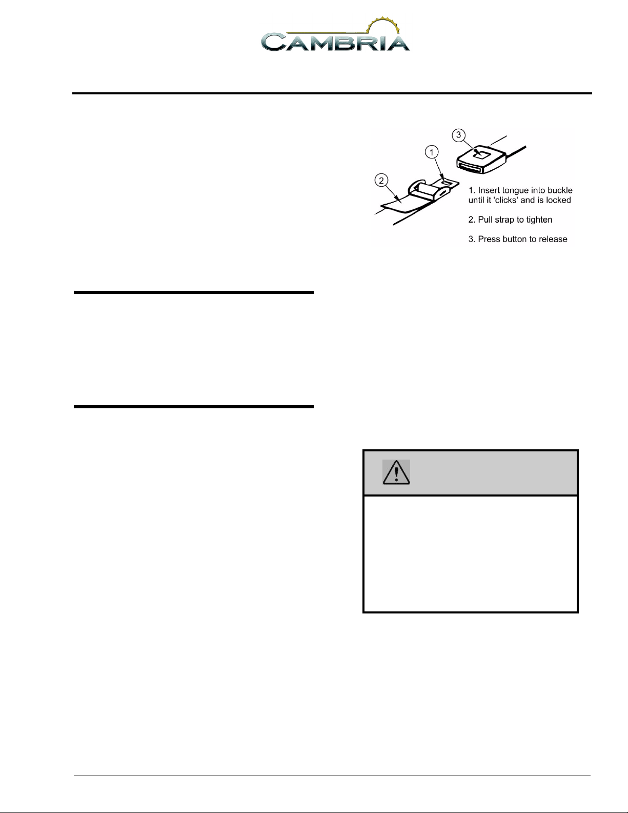
Adjustment:
To lengthen belt, turn tongue at a right angle
to belt and pull to desired length. To shorten, pull
loose end of belt.
To Fasten:
Be sure belt is not twisted. Grasp each part of
the belt assembly and push tongue into buckle.
Adjust to a snug fit by pulling the loose end away
from the tongue.
To Release:
SEAT BELTS
Seats intended for occupancy while the
vehicle is in motion are equipped with seat belts
for the protection of the driver and passengers.
Lap Belts
The lap belts must be worn as low as possible
and fit snugly across the hip area. Always sit
erect and well back into the seat. To gain full
protection of the safety belt, never let more than
one person use the same safety belt at any one
time, and do not let the safety belts become
damaged by pinching them in the doors or in the
seat mechanism. After any serious accident, any
seat belts which were in use at the time should be
replaced.
Press button in center of buckle and slide
tongue out of buckle.
WARNING
Snug and low belt positions are essential.
This will ensure that the force exerted by
the lap belt in a collision is spread over the
strong hip area and not across the
abdomen, which could result in serious
injury.
Only seats equipped with seat belts are to
be occupied while vehicle is in motion.
Seat Belt Care and Cleaning
• Be careful not to damage the belt webbing and
hardware. Take care not to pinch them in the
seat or doors.
• Inspect the belts and hardware periodically.
Check for cuts, frays, and loose parts.
Damaged parts should be replaced. Do not
remove or modify the belt system.
5 - DASH / AUTO
3-1
DRIVING YOUR MOTOR HOME
• Keep belts clean and dry. If the belts need
cleaning, use only a mild soap and water
solution. Do not use hot water. Do not use
abrasive cleaners, bleach or dyes. These
products may weaken the belts.
• Replace any belt assembly that was used
during a severe impact. Replace the complete
assembly even if damage is not apparent.
CHILD RESTRAINTS
A properly installed and secured child
restraint system can help reduce the chance or
severity of personal injury to a child in an
accident or during a sudden maneuver. Children
may be injured in an accident if they are seated in
a child restraint which is not properly secured.
A child restraint system is designed to be
secured in a vehicle seat by a lap belt or the lap
belt portion of a lap-shoulder belt. According to
accident statistics, children are also safer when
properly restrained in rear seating positions than
in front seating positions.
When purchasing a child restraint system:
1. Look for the label certifying that it meets all
applicable safety standards.
2. Make sure that it will attach to your vehicle
and restrain your child securely and
conveniently so that you are able to install it
correctly each time it is used.
3. Be certain that it is appropriate for the child's
height, weight and development. The
instructions and/or the regulation label
attached to the restraint typically provides this
information.
4. Review the instructions for installation and
use of the restraint. Be sure that you
understand them fully and can install the
restraint properly and safely in your vehicle.
SECTION 3
Tether Anchor Loop
KEYLESS ENTRY
The keyless entry system controls the locks
for the cab doors and the coach main entrance
door. The entrance door must be closed for the
lock to operate.
See your chassis owner’s manual for
instructions on operation of the keyless entry
system and remote battery replacement
information.
MIRRORS- EXTERIOR
Always adjust mirrors for maximum rear
visibility before driving off. Make sure the seat is
adjusted for proper vehicle control and that you
are sitting back squarely into the seat.
Side Mirror Head Adjustment
While sitting properly in the driver seat and
the mirror arms extended normally, have a helper
grip the mirror head by opposite upper and lower
corners and move it horizontally and vertically
for proper rearward vision.
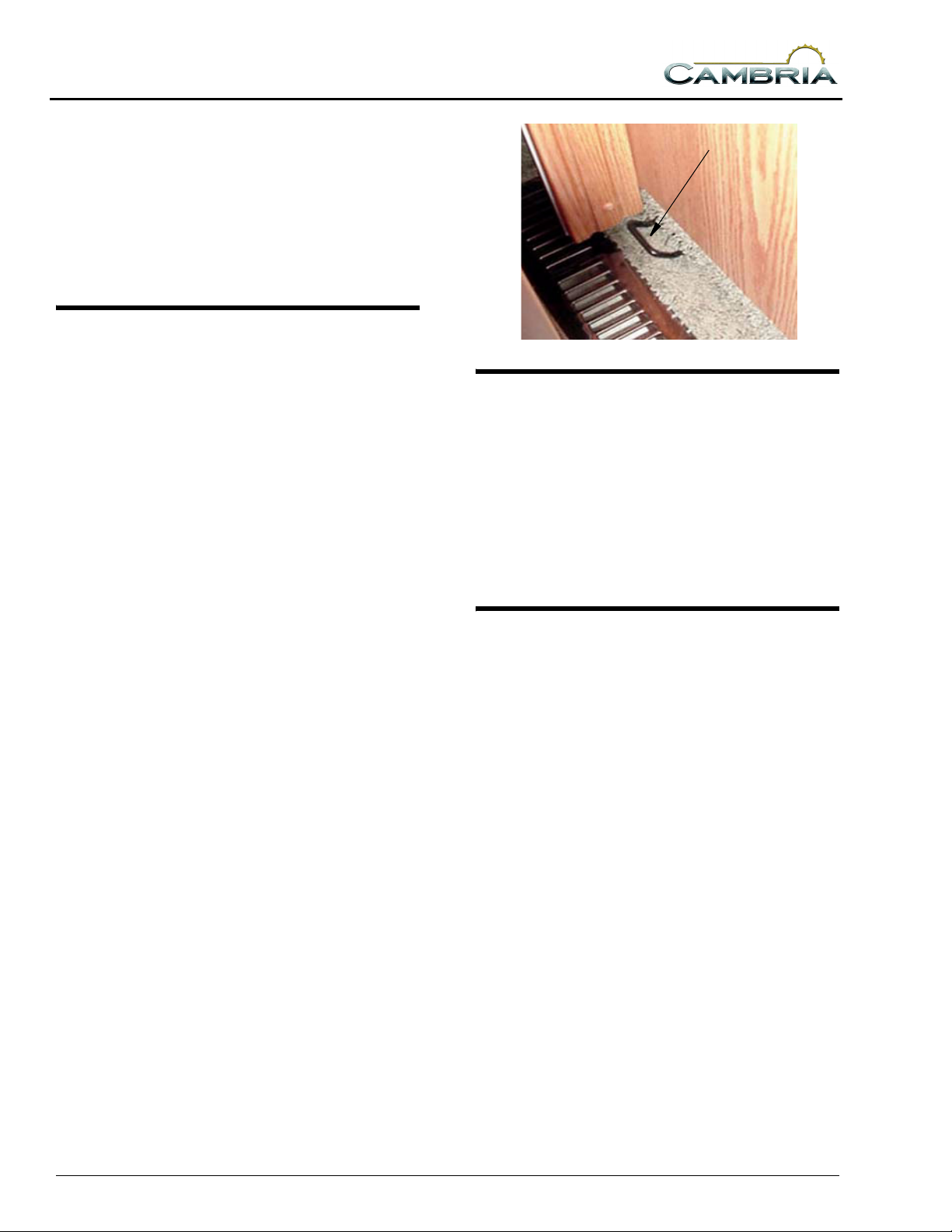
Tether Anchor Loop
If your coach has a dinette, a child seat tether
anchor loop is located in the floor of the coach
directly behind the forward facing dinette seat.
The dinette table must be in the lowered position
when a child seat is in use.
3-2
SECTION 3
DRIVING YOUR MOTOR HOME
Electric Remote with Defrost
-Optional
Mirror Adjustment
Control
For power mirrors, be sure the power
adjustment is in the middle of it’s adjustable
range, both up-down and right-left, before
adjusting the head position.
Mirror Heat Switch
If engine battery is discharged, press and hold
to the ON position while turning ignition key for
emergency starting power.
NOTE: The Aux Battery Switch by the entrance
door must be ON and house batteries
sufficiently charged for this feature to
work.
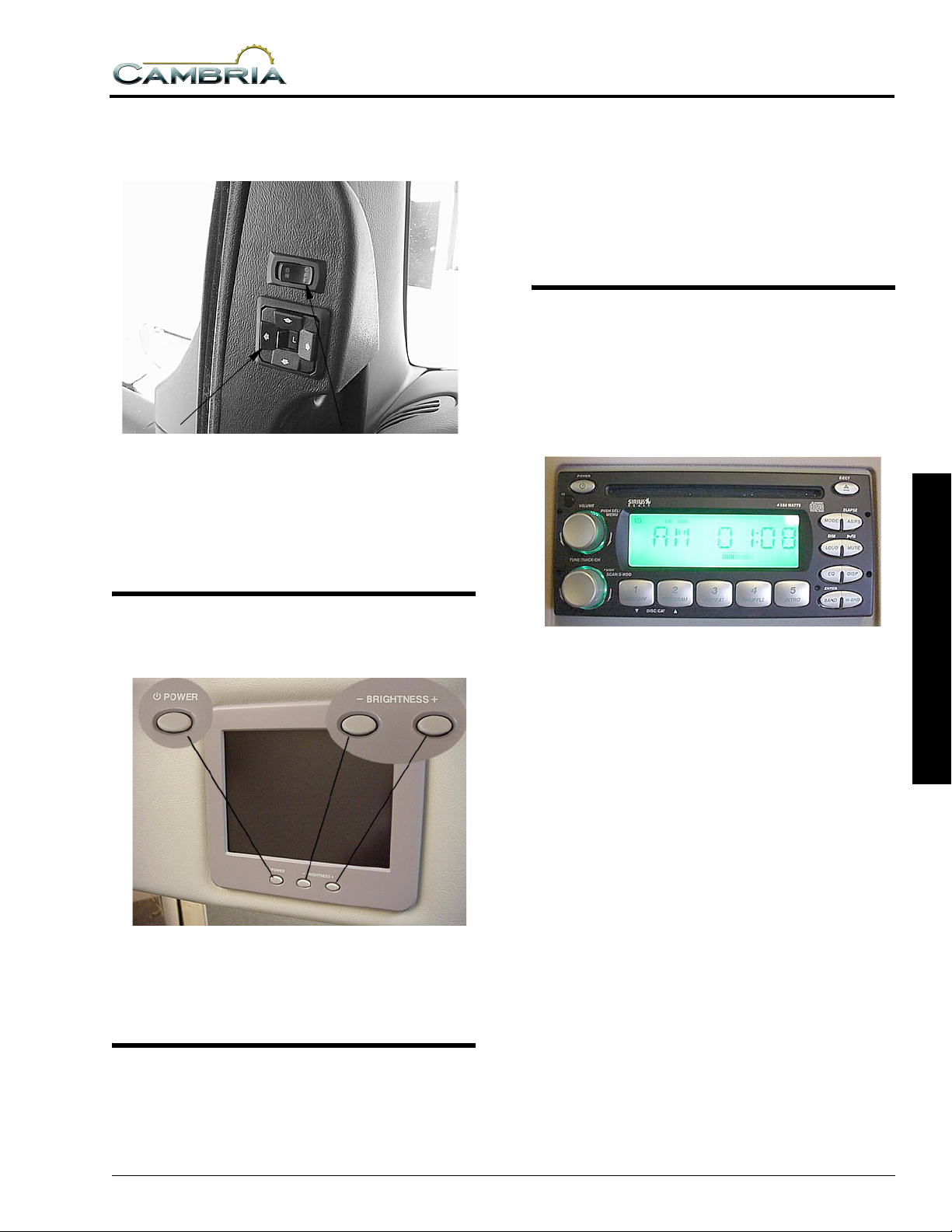
IN-DASH RADIO
The radio in your coach can receive AM/FM
stereo and Weather band stations. It also has a
compact disc (CD) player for your listening
enjoyment through quality high-output speakers
located in several areas of the coach.
REARVIEW MONITOR SYSTEM
- Optional
If your motor home is equipped with this
optional system, refer to the Owner InfoCase for
specific instructions provided by manufacturer.
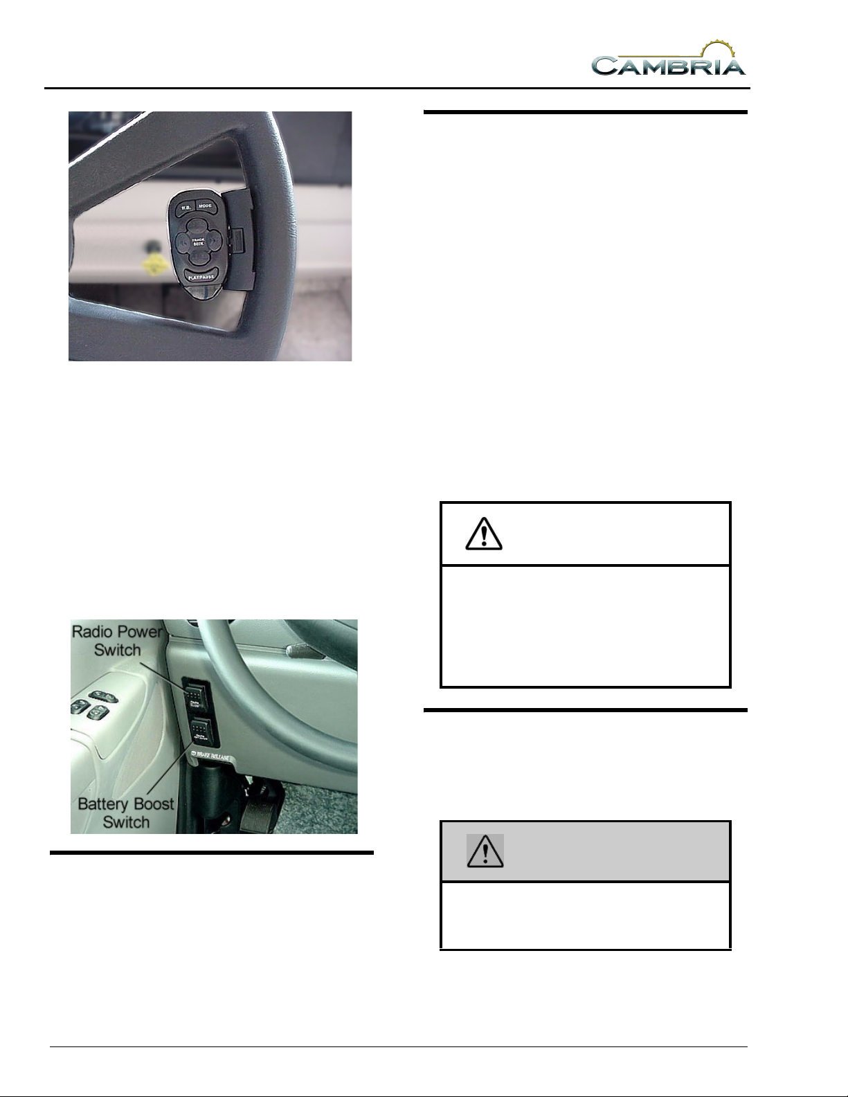
BATTERY BOOST SWITCH
This switch can be used to provide emergency
starting power from the motor home auxiliary
battery if the automotive battery is discharged.
Please refer to the manufacturer’s operating
guide in your Owner InfoCase for detailed
instructions on programming preset station
buttons and using this full-featured radio/audio
system.
Satellite Radio
- Optional
Your coach may be equipped with a Sirius
satellite radio receiver that plays through your
radio.
See the receiver manufacturer’s information
in your Owner InfoCase for programming and
operating instructions.
Radio Remote Controls
A steering wheel mounted remote control for
the radio lets you change radio stations or CD
selections without taking your eyes off the road
or hands off the wheel. See the radio owner’s
guide in your Owner InfoCase for remote control
instructions.
3 DRIVING YOUR MOTOR HOME
3-3
DRIVING YOUR MOTOR HOME
Radio Remote Control
(typical)
An additional hand-held remote allows these
same conveniences for the passenger. The handheld radio remote is in your Owner InfoCase.
Radio Power Switch
The radio power switch lets you connect the
dash radio to the coach batteries with the ignition
switch turned off for listening while parked. This
prevents accidental draining of the chassis
(starting) battery with prolonged use of the radio.
SECTION 3
ENGINE COOLING SYSTEM
Refer to your chassis operating guide for
information and precautions on filling, servicing
and checking the fluid level.
Do not remove the radiator cap while engine
and radiator are still hot. Always check coolant
level visually at the see-through coolant
reservoir.
NOTE: Your chassis engine cooling system is
filled with special extended-life coolant
that is not the same as common antifreeze available at retail outlets.
The coolant system MUST be refilled or
topped up with the same type of coolant
as equipped to maintain the special longlife properties.
Ford chassis use Ford Premium Gold
(GO 5), which is a golden color.
CAUTION
When refilling the coolant system of a
vehicle equipped with a rear auxiliary
automotive heater and motoraid water
heater, be sure to allow for additional
coolant capacity of the heater and its
supply and return hoses.
ENGINE ACCESS
Refer to your chassis operating guide. Do not
attempt to start the vehicle by hot-wiring.
3-4
TIRES
Improper tire pressure can result in tire
overloading and abnormal wear and also affects
handling, ride characteristics and fuel economy.
WARNING
Make sure all replacement tires are of the
same size and ply rating as those
installed as original equipment.
See the Vehicle Certification Label for tire
information.
SUSPENSION ALIGNMENT AND TIRE BALANCE
The front suspension and steering system of
this vehicle was factory aligned using highly
accurate equipment prior to delivery to the
dealership. However, we recommend that
alignment should be checked and adjusted after
you have fully loaded the motor home according
to your personal needs. Thereafter, the alignment
should be periodically inspected to help prevent
uneven tire wear.
Any excessive or abnormal tire wear may
indicate worn or misaligned suspension or
steering, unbalanced tire or other tire/suspension
problem.
Alignment can be affected by worn steering/
suspension parts or by incidents which happen
during driving, such as hitting a curb, pothole or
railroad track, etc. Improper alignment can cause
tires to roll at an angle and wear unevenly. It may
also cause the vehicle to “pull” to the right or left.
Have your dealer inspect your vehicle’s
suspension and steering components periodically
for misalignment or wear.
Out-of-balance tires will not roll smoothly and
can lead to vibrations and uneven tread wear such
as cupping and flat spots. Tires may need to be
balanced if uneven wear is detected or if ride
comfort decreases noticeably.
See your chassis operating guide for further
information.
SECTION 3
DRIVING YOUR MOTOR HOME
The air bags can be adjusted independently if
necessary to equalize a load, however we
recommend maintaining the same pressure in
both air bags whenever possible to ensure that the
vehicle remains level.
Adjustment
The air bag fill valves are located in the water
service center compartment.
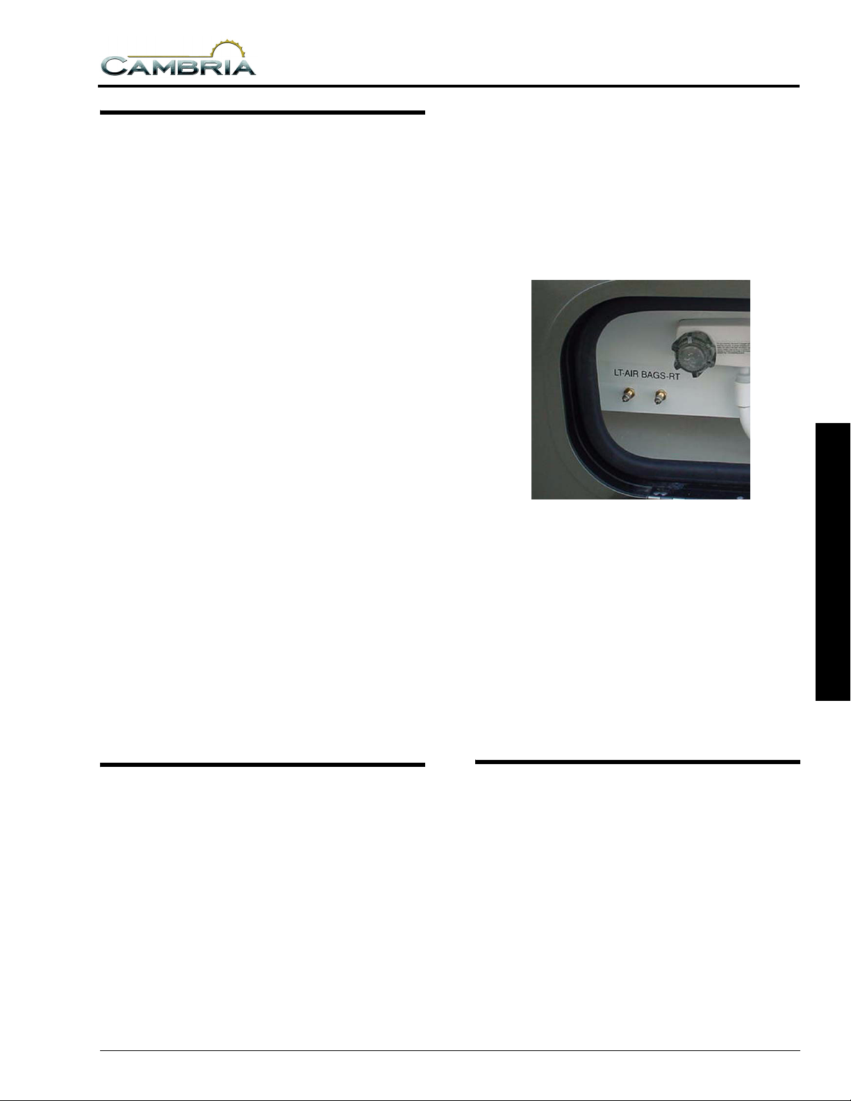
Rear Air Helper Spring Valves
(located in water service center compartment)
Recommended Pressure: start at 20-25 psi
Minimum Operating Pressure: 10 psi
Maximum Operating Pressure: 100 psi
Too much air pressure in the air helper springs
will result in a firmer ride, while too little air
pressure will allow the air helper spring to bottom
out over rough road conditions. Too little air
pressure will also not provide the improvement in
handling that is possible.
3 DRIVING YOUR MOTOR HOME
REAR AIR HELPER SPRINGS
- Optional
Check and adjust the air bag pressure
periodically to maintain optimal ride and
handling characteristics according to cargo
weight.
The air springs (air bags) are an enhancement
to the standard suspension system to provide
adjustable load and ride conditions. This feature
is not intended to increase the load capacity of the
rear axle or vehicle.
LIGHTS
All exterior lights should be checked for
proper operation each time the vehicle is
prepared for a trip. Any bulbs which fail to light
should be checked and replaced, when necessary,
with a new bulb of the same size. A failure of
more than one light, such as both taillights not
operating, may indicate a burned out fuse. Check
fuse and replace with one of the same rating
when necessary. If a fuse is not the cause of the
problem, the wiring system should be checked
immediately by an authorized service center.
3-5
SECTION 3
DRIVING YOUR MOTOR HOME
Refer to your chassis operating guide for
further information.
AUTOMOTIVE 12-VOLT FUSES AND CIRCUIT BREAKERS
See the Chassis Owner’s Manual in your
Owner InfoCase for information.
LOADING THE VEHICLE
NOTE: Your motor home’s load capacity is
designated by weight, not by volume, so
you cannot necessarily use all available
space when loading your motor home.
• Store or secure all loose items inside the motor
home before traveling. Possible over- looked
items such as canned goods or small
appliances on the countertop, cooking pans on
the range, or free-standing furniture items can
become dangerous projectiles during a
sudden stop or evasive maneuver.
• Be aware of GVWR, GAWR and individual
load limit on each tire or set of duals.
When loading the vehicle, distribute the cargo
load so that you do not exceed either the Front or
Rear Gross Axle Weight Rating (GAWR) or the
Gross Vehicle Weight Rating (GVWR). The
Gross Axle Weight Rating (GAWR) means the
weight value specified by the chassis
manufacturer as the load carrying capacity of a
single axle system as measured at the tire-toground interfaces. This is the total weight a given
axle is capable of carrying. Each axle has its own
rating.
Have your vehicle weighed to determine the
proper load distribution for your vehicle. Also
distribute cargo side-to-side so the weight on
each tire or dual set does not exceed one half of
the GAWR for either axle.
For example, if the Front GAWR is 6,000 lbs.,
there should be no more than 3,000 lbs. on each
tire. (If the left side weighs 3,100 lbs. and the
right side weighs 2,700 lbs., at least 100 lbs. of
the load must be shifted from the left side to the
right side.) The GVWR is listed on the Vehicle
Certification Label. (See sample in Introduction
Section).
The GCWR (Gross Combination Weight
Rating) means the maximum allowable loaded
weight of this motor home and any towed trailer
or towed vehicle. If trailer towing is not
recommended, the GCWR will equal the
GVWR.
NOTE: We recommend that you dump all
holding tanks before traveling to avoid
carrying unnecessary weight.
CAUTION
The weight of the loaded vehicle
(including options, attachments,
passengers, water, fuel, luggage, trailer
tongue load and all other cargo) must not
exceed the GVWR or GAWR of either
axle.
ROOF LOADING
The roof is capable of carrying up to 10
pounds per square foot to a maximum of 100
pounds while the vehicle is in motion.
When the vehicle is stationary, a cargo load of
100 pounds plus the weight of a 225 pound
person to load the cargo or to conduct inspection
and maintenance is permissible.
Weight added to both the roof and the trailer
hitch contribute to the gross vehicle weight,
which must not exceed the vehicle’s GVWR.
WEIGHING YOUR LOADED VEHICLE
To check the weight of your fully loaded
coach, locate a commercial weighing scale that is
capable of weighing large trucks.
Loading
Load your vehicle completely as if you were
going on a long trip, with everything you would
carry, including food, clothing, bedding, lawn
3-6
SECTION 3
DRIVING YOUR MOTOR HOME
chairs, etc., a full fuel tank, full LP tank, and a
partial tank of fresh water - but empty holding
tanks.
Finding a Scale
In urban areas, the most common places to
find a public access scale are commercial truck
stops. In rural areas, most grain storage elevators
have scales available. Most scales charge a
nominal fee for weighing a vehicle.
Weighing
There is typically a scale operator to direct
you but the basic routine is to take three separate
weights - front axle, whole vehicle, and rear axle.
You will first drive only your front wheels onto
the scale pad, then drive ahead so that the whole
vehicle is on the scale, then finally pull off until
just the rear wheels are on the pad.
Front Axle Only
these weights to the weight ratings listed on your
Vehicle Certification Label to use as a guideline
for future loading limits and weight distribution.
The gross weight of the vehicle must not
exceed the Gross Vehicle Weight Rating
(GVWR) specified on the Vehicle Certification
Label. The front and rear axle weight also must
not exceed the corresponding Axle Weight
Rating specified on the Vehicle Certification
Label.
Corner Weighing (Side-to-Side)
Weighing each corner of the coach separately
(single L/R front wheels or L/R rear dual sets) is
an accurate method to determine how to
distribute your cargo to avoid overloading,
especially on tires.
To determine the weight distribution on each
tire or dual set, you will need to find a scale
capable of weighing side-to-side, or all four
‘corners’ of the vehicle, separately. A truck scale
may be used if the ground is level with the scale
surface and the scale has clearance to drive one
side of the coach onto the scale as shown.
Drive the coach on the level area next to the
scale and straddle the scale so that only one side
of the coach will be on the scale pad. Pull only the
front wheel onto the pad as shown.
Both Front and Rear Axles
Rear Axle Only
You will receive a weight ‘ticket’ that states
your current Front Axle Weight, Rear Axle
Weight and Vehicle Weight. You can compare
3 DRIVING YOUR MOTOR HOME
Weighing Left Front ‘Corner’
When the front wheel has been weighed, pull
the coach straight ahead until only the rear wheel/
dual set is on the scale pad as shown.
Weighing Left Rear ‘Corner’
3-7
SECTION 3
DRIVING YOUR MOTOR HOME
After the rear wheel set has been weighed,
turn the coach around and repeat this process for
the other side.
The load on each wheel or dual-wheel set
should not exceed one-half of the corresponding
GAWR. For example, if the GAWR for the rear
axle is 12,000 lbs., then the load on each rear dual
set (left rear duals or right rear duals) should not
exceed 6,000 lbs.
Tires must be filled to the recommended air
pressure for the highest loaded tire set on that
axle. For example, on the rear axle, if the left side
weighs more than the right, fill the left tires to the
pressure required for that weight, then fill the
right tires to the same pressure as the left ones.
If your actual weight is considerably less than
GAWR, you may be able to lower your tire
pressure. See a tire dealer for a load/pressure
chart.
NOTE: The Hitch Load weight from a Towed
Vehicle or carrier box must also be
counted on the Rear GAWR and
subtracted from the rear axle cargo
capacity. If you tow other than a light
trailer or a vehicle by means of a tow bar,
you should have your trailer coupled
when weighing your motor home.
Be aware that hitch load can affect handling
characteristics. The more weight on the hitch, the
lighter the front end will feel at the steering
wheel.
Because of individual vehicle use and loading
habits, we recommend weighing the vehicle
while fully loaded to avoid exceeding any of the
listed Gross Weight Ratings. See “Vehicle
Certification Label” in the Introduction Section
for information on gross weight ratings.
Towing will affect vehicle handling,
durability and fuel economy. Exceeding any of
the listed Gross Weight Ratings will result in
unacceptable overall vehicle performance.
Maximum safety and satisfaction when towing
depends on proper use of correct equipment.
Select a drawbar that mates properly with the
towing hitch receiver and provides proper
alignment to the vehicle tow bar. The tongue of
the tow bar must be as close as possible to
parallel with the ground when attached to the
hitch ball.
Installation of a proper trailer brake system is
recommended. Check state regulations on trailer
weight and trailer brake requirements to be sure
you select the right equipment before towing.
NOTE: If you tow a car or trailer that weighs
over 1,000 lbs., it may need to be
equipped with automatically activated
brakes. Check your state laws.
Before descending a steep or long grade when
towing a trailer, reduce speed and shift into a
lower gear to control vehicle speed. Avoid
prolonged or frequent application of brakes
which could cause overheating and brake failure.
CAR OR TRAILER TOWING
Hitch pulling capacity: 5,000 lbs. max.
Tongue weight:350 lbs. max.
The factory installed towing hitch on this
coach is capable of pulling 5,000 lbs. load (max.),
however the vertical (tongue) weight may vary
according to chassis and model combinations. Do
not exceed either the GVWR, the rear axle
GAWR, or the chassis GCWR by the combined
loaded weight of the coach and the towed
vehicle. See preceding items “Loading the
Vehicle” and “Weighing Your Loaded Vehicle”
for explanation of weight ratings.
3-8
WARNING
For safe towing and vehicle handling,
maintain proper trailer weight distribution.
The total weight of the motor home and
the vehicle towed must not exceed the
Gross Combined Vehicle Weight rating.
See table in Section 1 to obtain the Gross
Combined Vehicle Weight rating for your
chassis.
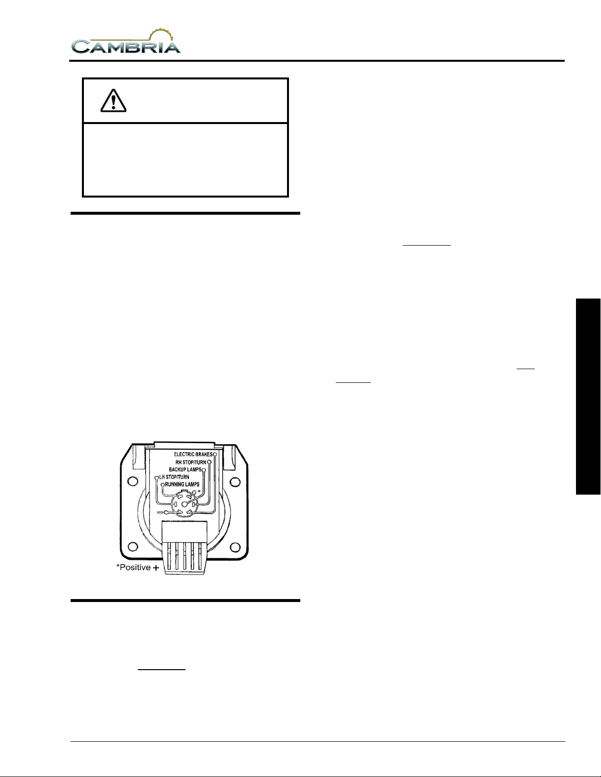
CAUTION
Exceeding any of the recommended
gross vehicle weight ratings may result in
vehicle damage.
Do not install a frame equalizing type
hitch on your vehicle.
TRAILER WIRING CONNECTOR
Your coach is pre-wired for trailer or car
towing lights with a 7-pin socket. The connector
plug is supplied in the coach parts package
provided to you by your dealer when you took
delivery of the vehicle.
The diagram below shows proper connection
of trailer or tow vehicle wiring to the coach light
system. The ‘pigtail’ assembly with the (car/
trailer end) connector plug should be wired by a
qualified technician. Provision for an electric
brake controller is located near the steering
column.
SECTION 3
DRIVING YOUR MOTOR HOME
installed by the motor home manufacturer,
dealer, or owner. This value is found on the
Vehicle Certification Label.
Gross Axle Weight Rating (GAWR):
This is the total weight a given axle is capable
of carrying, measured at the ground. Each axle
has its own rating. These values are also found on
the Vehicle Certification Label: front, rear, and
tag, if applicable.
Gross Combination Weight Rating (GCWR):
This is the maximum allowable weight of the
motor home and loaded trailer, including the
items noted in GVWR. The “trailer” can be an
actual trailer, a vehicle towed on a towing dolly,
or a vehicle towed by means of a towing bar.
GCWR is typically specified based on durability
and performance of the tow vehicle drivetrain:
engine cooling systems, transmission, drive line,
drive axle, and others. The tow vehicle brakes
may be rated for operation at GVWR, not
GCWR.
NOTE: If the “trailer” weighs 1,000 lbs. or
more, state or provincial laws/
regulations may require the “trailer” to
be equipped with brakes that are
activated when the motor home brakes
are applied. The user is responsible to
know and understand the laws of the
state or province being traveled. The
Department of Transportation in a given
state or province should be able to
provide specific information.
3 DRIVING YOUR MOTOR HOME
TOWING GUIDELINES
Gross Vehicle Weight Rating (GVWR):
This is the maximum allowable weight of the
fully loaded vehicle. Included are fuel, water, LP,
passengers, cargo, tools, and optional equipment
Hitch Ratings:
SAE Standard J684 defines
Class 1 trailers as “GVWR not to exceed
2,000 lbs.”;
Class 2 trailers as “GVWR over 2,000 lbs. and
not to exceed 3,500 lbs. GVWR”;
Class 3 trailers as “GVWR over 3,500 lbs. and
not to exceed 5,000 lbs. GVWR”;
Class 4 trailers as “GVWR over 5,000 lbs. and
not to exceed 10,000 lbs. GVWR”.
3-9
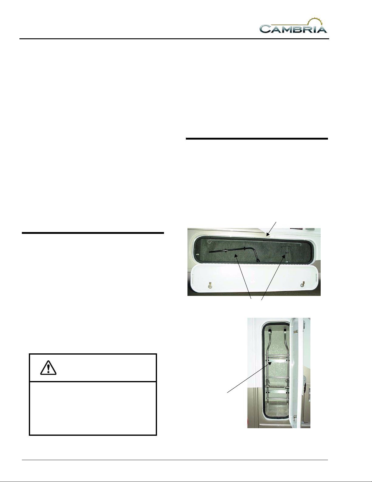
SECTION 3
DRIVING YOUR MOTOR HOME
Hitches are to be permanently marked with
“Maximum trailer GVWR to be drawn” and
“Maximum vertical tongue weight to be
imposed...” The SAE standard does not specify a
vertical load rating, as such. Traditionally,
hitches are labeled 3,500/350 as Class 2 and
5,000/500 as Class 3.
The vertical tongue load value of 10 percent of
drawn rating apparently comes from the
collective experience that 10 percent is the
minimum value that provides stable towing of a
trailer. Ford’s towing guide suggests 10 to 15
percent for trailers over 2,000 lbs. (Hitch ratings
are independent of towing vehicle ratings.)
NOTE: Some Winnebago Industries models
equipped with a Class 3 hitch may have a
label limiting vertical tongue load to 350
lbs.
The user must verify that the hitch
equipment being used is adequate for the
application.
Descending A Hill
When going down a long grade, you may need
to manually shift to a lower gear rather than
keeping your foot on the brake pedal. A lower
gear will allow the engine to provide a degree of
braking action. Holding your foot on the brake
pedal for an extended period may cause brakes to
overheat, which could cause you to lose control
of the vehicle. See your chassis operating guide
for specific information.
TOOLS & LADDER STORAGE
The roof ladder extension and various
supplied tools are stored in clips on the walls of
one or two of the exterior storage compartments.
Actual locations depend on storage compartment
configuration of your model. The following
photos show typical arrangements.
Awning Hook
MOUNTAIN DRIVING
Special techniques must be used when driving
in mountainous or hilly country.
Climbing A Hill
The transmission will automatically
downshift as needed to climb most hills. If the
hill is long or very steep, however, you may need
to manually shift to a lower gear to keep the
transmission from repeatedly upshifting and
downshifting. Select the lowest adequate gear
range for the duration of the incline. See your
chassis operating guide for specific information.
CAUTION
Observe the engine temperature gauge
more frequently than normal. If
overheating occurs, pull off to the side of
the road and allow the engine to
thoroughly cool before refilling the
radiator and restarting the engine.
Tire Tools
Ladder Extension
3-10
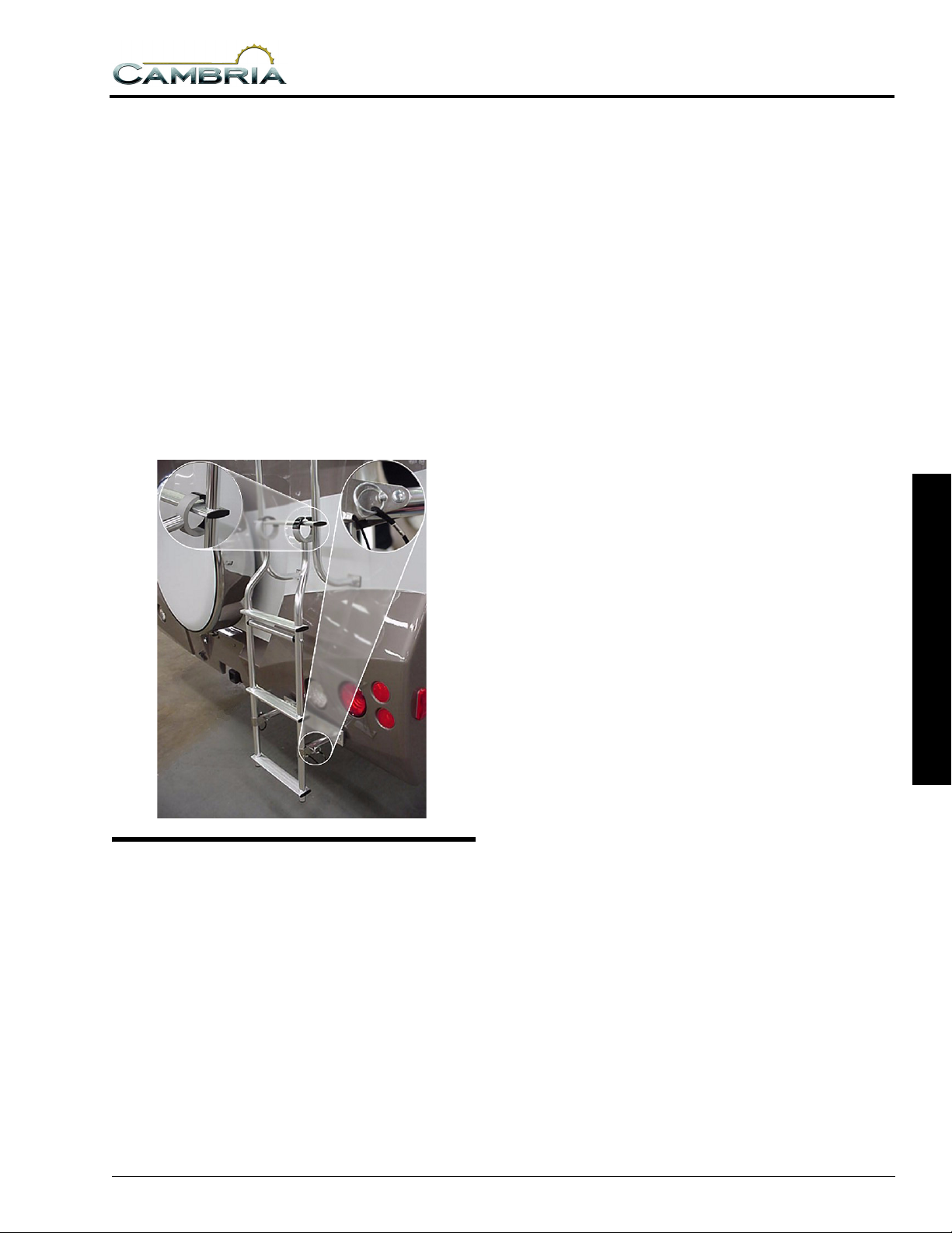
SECTION 3
DRIVING YOUR MOTOR HOME
Ladder Extension
To use the ladder extension:
• Unfold the ladder support and pin into place as
indicated in the photo.
• Hold the ladder extension horizontally with
the bumper pad pointing downward.
• Slide the open ends of the C-shaped retainers
over the lowest ladder rung as shown in the
photo.
• Lower the extension into place and push
downward while adjusting it slightly to ‘set’
the retainers.
• The ladder is now ready to use.
• Reverse steps to remove and store.
To ensure that exterior storage compartment
doors have latched properly, press firmly on the
bottom edges of the doors with the palms of your
hands. If the door is ajar you will hear and feel a
loud ‘click’ when the latches engage properly.
STORAGE COMPARTMENT DOORS
The high-density gaskets used on the exterior
storage compartments are designed to provide a
more positive seal against dust and weather.
Sometimes this seal firmness can inhibit
complete latching of the compartment doors if
they are simply ‘dropped shut’ or closing force is
applied only to the center of the door.
3 DRIVING YOUR MOTOR HOME
3-11

 Loading...