

Page 1
RF POWER AMPLIFIER
The power amplifier is intended to increase receiver sensitivity and c ompens ate for various line losses (in
the feeder, connectors and cable) as well as signal losses due to electromagnetic radiation, in order to
attain maximum allowable signal emis sion. T he bi-directional amplifier operates in half-duplex mode in
the 2.4 - 2.5 GHz ISM frequency range.
The amplifier assembly consists o f four main components:
1. Low-noise receive amplifier, transmit amplifier, and switching control unit assembled in a sealed
enclosure.
Bandpass filter, which determines the usable frequency band of the amplifier and its sensitivity to
2.
interference outside of the selected RF band.
DC power injector. T he DC power injector s hould be lo cated near a transmitting device, suc h as a
3.
radio modem or a bridge. The power injector c onnects to the transmitting device and the amplifier
assembly via 50 Ohm coaxial cable.
110-220 VAC Power supply.
4.
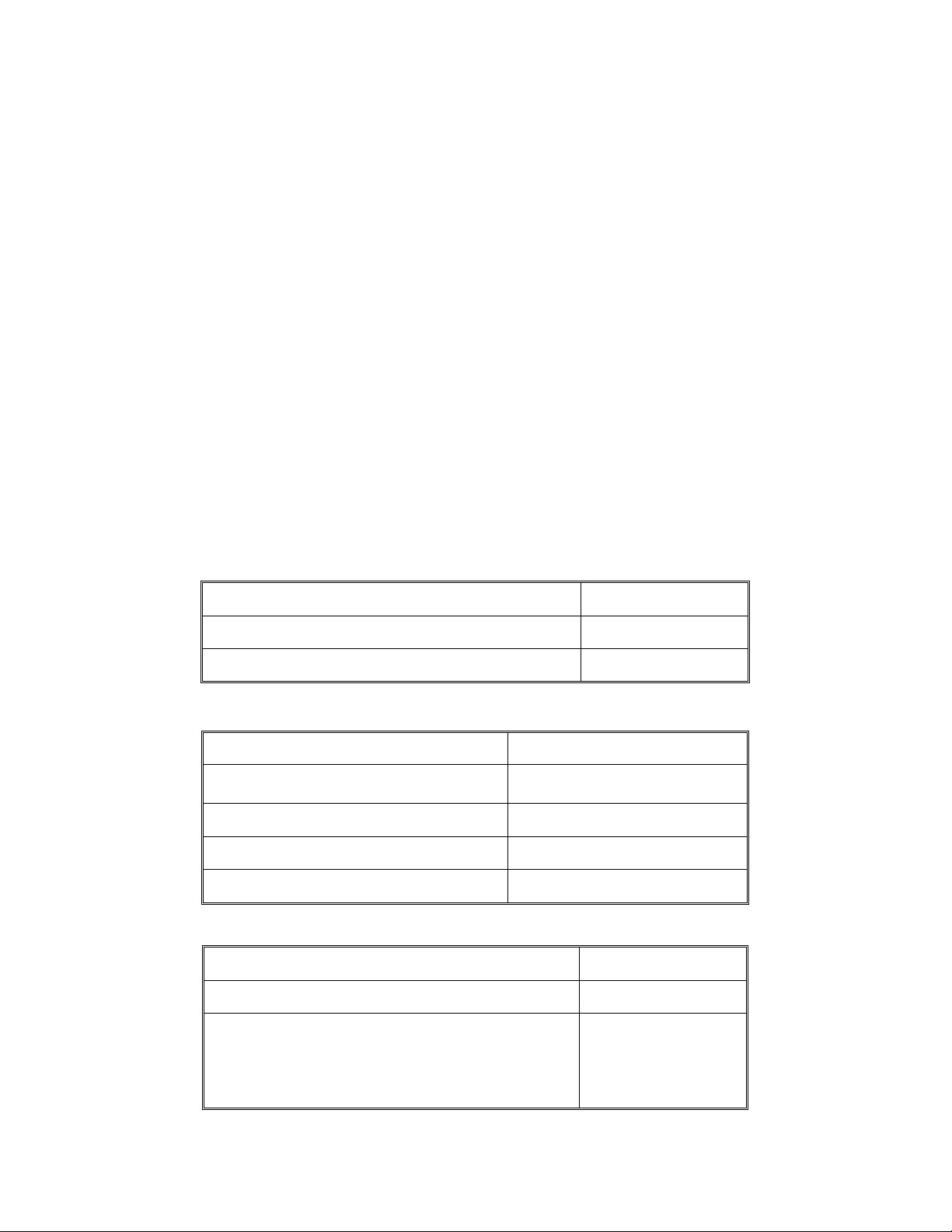
Technical Characteristics
Receive Amplifier
Gain, dB 25.0 ± 3.0
Nois e fi gure, d B ≤ 3.0
Input saturation power, mW ≅ 10
Transmit Amplifier
Automatic gain & power control
Input power, mW 0.5 – 100
Max Output power, mW 800.00
Switching power, mW 0.5 ± 0.3
Switching time, mks ≤ 0.5
Bandpass Filter
Frequency band (with ripple 0.5 dB ), GHz 2.4 – 2.5
Attenuation in frequency band 2.4–2.5 GHz, (dB) 0.5
Out-of-Band Attenua tion
Amp_250_Inst_12_99
2 GHz, (dB)
@
3 GHz, (dB)
@
60
60
Page 1 of 5
Page 2

DC Power Injector
Frequency band (with ripple 0.5 dB ), GHz 2.4 – 2.5
Attenuation in frequency band 2.4–2.5 GHz, (dB) 0.6
RF connector type N-female
Powe r Supply
DC out, V 12
Max output power, W 12
DC Connector type BNC – male
Operating temper ature r ange
-50°C — +50°C
The filter determines the frequency cha rac teris tic s of the amplifier. In sta ndard c onfiguration the amplifier
is shipped with a 100 MHz filter, main freque ncy of 2445 MHz, main frequency attenuation of 0.5 dB, and
an input shunt for quasi-direct currents. At the foregoing settings signal attenuation is > 60 dB in the 0 -
2.4 GHz and 2.5 - 18 GHz ranges.
The amplifier/filter set includes the following:
Item Quantity
Amplifier / Filter 1
DC Power injector 1
Power supply 1
Amplifier / filter mounting plate 1
U-shaped mast mounting brackets 2
Grounding strap 1
Amp_250_Inst_12_99
Page 2 of 5
Page 3

Installation Instructions
Important Notice:
Read the following installation instructions and all warnings carefully prior to installing the
amplifier. Failure to follow installation instructions or tampering with the amplifier or the
power supply will void the warranty.
Install the amplifier mounting plate, with the amplifier and filter a ttac hed, on a mast near the e xternal
1.
antenna, using two U-shaped brackets (included). The amplifier can also be installed horizontally
on a mounting s ta nd through predrilled holes in the mounting plate .
2. Connect the amplifier to the antenna and DC power injector, as marked, with 50 Ohm coaxial cable.
Important: In order for the amplifier to operate properly, and to avoid damage to the amplifier and
the power supply, the maximum input power to the amplifier must not exceed 100mW. User must
check for proper attenuation.
3. Following ins talla tion, a weather sealant of 100% s ilicone over elec trical tape must be applied to all
external connectors to protect them from moisture (moisture can cause increased s ignal losses in the
feeder, diminis hed transmission quality, and possible da mage to the connectors and the amplifier).
Grounding
4.
grounding strap to the mas t with a bolt. C heck the ground on the amplifier a ssembly with an Ωmeter.
. Ensure that the mounting mas t is properly grounded. Connec t the amplifier assembly's
Warning:
Improper grounding can adversely affect amplifier performance and may lead to equipment
damage or personal injury. Failure to properly ground the amplifier will void the warranty.
The amplifier is not designed to withstand a lightning strike. Amplifier warranty does not
apply to damage caused by lightning.
Amp_250_Inst_12_99
Page 3 of 5
Page 4

Operation of the Amplifier
• On power up, the amplifier will be in a "receive" mode. The mode switches to "transmit" when the
amplifier receives a signal from a radio modem or another transmitting device. A red light on the DC
injector indicates that the amplifier is in a " transmit" mode. T he red light blinks when the amplifier is
connected to a radio bridge, and is half-lit when the a mplifier is connected to a radio modem.
• A constant red light indicates that the amplifier is continuously in the "transmit" mode and is not
communicating properly. This is an abnormal condition that can be caus e d by a ny of the following:
High noise level in the feeder of the transmitting dev ice
and other transmitting dev ice s de ve lop e le va ted natural noise leve ls , e ve n in the "receive"
mode. This noise can cause the amplifier to switch from "receive" to "transmit" mode,
causing interruptions in communications. This problem can be diagnose d by measuring
the natural noise level of the transmitting device with an oscilloscop e. If the problem is
detecte d, the transmitting device s hould be replaced.
External inte r ference
the amplifier to intermittently switch to "transmit" mode. This condition ha s be en o bs e rved with
certain brands of radio modems, due to the modems' poor shielding characteristics. T hus, if the
transmitting device is not adeq ua tely shielded, several su ch device s op era ting in clos e proximity
can interfere with the amplifier's operation.
. If the amplifier is not properly grounded, external inte rference can cause
. With time, some radio modems
• If the red light does not come on at all, the cable could be defective, or the cable length may exceed
maximum a llowable le ngth.
Important FCC Notice:
Operation of RF power amplifiers in the United States is subject to the Federal Communications
Commission's regulations in accordance with 47 USC 302. Use of the amplifiers with Part 15 transmitters
may be restricted by federal law. User is responsible for compliance with all applicable laws and
regulations.
FCC Regulatory Notice
This equipment complies with FCC Regulation 15.247, which specifie s the license-free opera tion
of direct sequence , spread-spectrum wireless communications device s. This device operates in
the 2.4 to 2.4835 GHz frequency band reserved for industrial, scientific and medical applications.
Since this device ge nerates radio frequency wave s, it may interfere with othe r radio signals in
the same area unless the proper installation and operations procedures are followed. It has been
Amp_250_Inst_12_99
Page 4 of 5
Page 5

pr ov e n in tes t ing th a t this dev ic e co mplie s with in t h e limit s o f FC C R e gula t io n s t h a t a re d e sign e d
to provide reasonable protection against such interference in a commercial environment.
NOTE:
Installation and maint enance must be perf or med by authorized
Winncom Technologies
personnel, or those per sons proper ly tr ained and authorized to do such procedures.
Technologies
is not responsible f or any damages, incidental or ot herwise, in connection with use of this
manual by anyone not described above.
In order to comply with
FCC adopted RF Exposure Requirements
be insta lle d in a manner that will provide
or member of the public
.
20 cm
clearance from the ant enna
, the 23 inch Omni antenna must
to any personn el
,
Winncom
Amp_250_Inst_12_99
Page 5 of 5
 Loading...