

WINNCARE DUO DIVISYS Series Manual
85670 SAINT PAUL MONT PENIT
Site Internet : http://www.winncare.fr
4 Le Pas du Château
TEL : +33 (0)2 51 98 55 64
FAX : +33 (0)2 51 98 59 07
Email : info@medicatlantic.fr
DUO DIVISYS
DO8C/P-8/9
2019_04_01 580046 Anglais

1. TRANSPORT AND STORAGE 4
2. BED ENVIRONMENT CONDITIONS 4
3. GENERAL USE 4
3.1. PRECAUTIONS FOR USE 4
3.2. ELECTRICAL CHARACTERISTICS 6
3.2.1. ELECTRICAL DATA 6
3.2.2. PROTECTION LEVEL AGAINST DUST AND LIQUID PENETRATION 7
3.2.3. ELECTROMAGNETIC COMPATIBILITY 8
3.2.4. EQUIPOTENTIALITY 9
4. BED BOARDS 120/140/160CM WIDTH COMPATIBLE 10
5. COMPATIBLE ACCESSORIES 11
6. USE 12
6.1. PURPOSE OF BED 12
6.2. SPECIFIC PRECAUTIONS FOR USE 12
6.2.1. RESIDUAL RISKS 12
6.3. GENERAL DESCRIPTION 13
6.4. TECHNICAL CHARACTERISTICSTECHNIQUES 13
6.4.1. DIMENSIONAL 13
6.4.2. WEIGHT 14
6.4.3. NOISE 14
6.5. ELECTRICAL CONNECTION DIAGRAM 15
6.5.1. DOUBLE ELECTRIC STATEMENTS FOLDER, DOUBLE STATEMENTS ELECTRIC FOLDING LEGS WITH KNEES 15
6.5.2. DOUBLE ELECTRIC STATEMENTS FOLDER, DOUBLE STATEMENTS ELECTRIC FOLDING LEGS WITH KNEES 15
6.6. ELECTRICAL SYSTEM INITIALIZATION 16
6.7. REMOTE CONTROL 17
6.8. BRACKING 18
6.8.1. INDIVIDUAL BRACKING 18
7. ASSEMBLING AND DISMANTLING 18
7.1. ASSEMBLING 18
7.2. DISMANTLING 19
8. OPERATION OF THE SLEEPING SURFACE 20
8.1. BACK REST 20
8.1.1. STANDARD BACK REST 20
8.1.2. BACK REST WITH TRANSLATION 20
8.1.3. EMERGENCY RELEASE OF THE BACK REST (CARDIO PULMONARY RESUSCITATION) 21
8.2. LEG REST 21
8.2.1. LEG REST WITH MANUAL CRANK (C) 21
8.2.2. LEG REST WITH ELECTRIC FOLDING (P) 21
9. INSTALLATION OF ACCESSORIES 21
9.1. BOARDS 21
2

9.2. METAL SIDE RAILS 22
9.3. WOODEN BARRIERS 23
9.4. ALUMINUM HALF SIDE RAILS 24
9.5. ANGLED LIFTING POLE AND IV STAND 25
10. MAINTENANCE 26
10.1. IDENTIFICATION 26
10.2. INSTRUCTIONS FOR DISMANTLING THE MOTORS 26
10.3. MAINTENANCE 27
10.4. QUALITY INSPECTION OF MEDICAL BEDS 28
10.5. CLEANING AND DISINFECTION 29
10.6. LIFETIME 30
10.7. GARANTIES 30
10.8. TROUBLESHOOTING GUIDE 31
11. SCRAPPING 32
3
Dear Sir/Madam,
You have acquired a WINNCARE medical bed equipped with its accessories, and we thank you for your
custom.
Our beds and their accessories are designed and manufactured in compliance with the essential
requirements of the European Directive 93/42/EEC and 2007/47/EEC.
They are tested in conformity with standard EN 60601-2-52 (2010) in their commercial configurations,
including the boards and accessories that we manufacture, so as to ensure you maximum safety and
performance.
As a result, maintenance of the contracted good’s warranty depends on compliance with the conditions for
use recommended by WINNCARE and the use of original accessories, which also guarantees you safe use
of the medical bed and its accessories.
1. TRANSPORT AND STORAGE
For transport, the bed should be in its low position, on a pallet, and strapped and protected. The wired control
and supply lead should be attached to the bed base.
The head and footboards are protected and strapped to the sleeping surface.
The bed should be transported upright when in its original packaging in compliance with the instructions printed
on the packaging.
It is strictly forbidden to stack packages weighing over 60kg/m², whatever
position they are in.
Before transporting or dismantling the bed, make sure the back and leg rests
are fixed to the frame of the bed base.
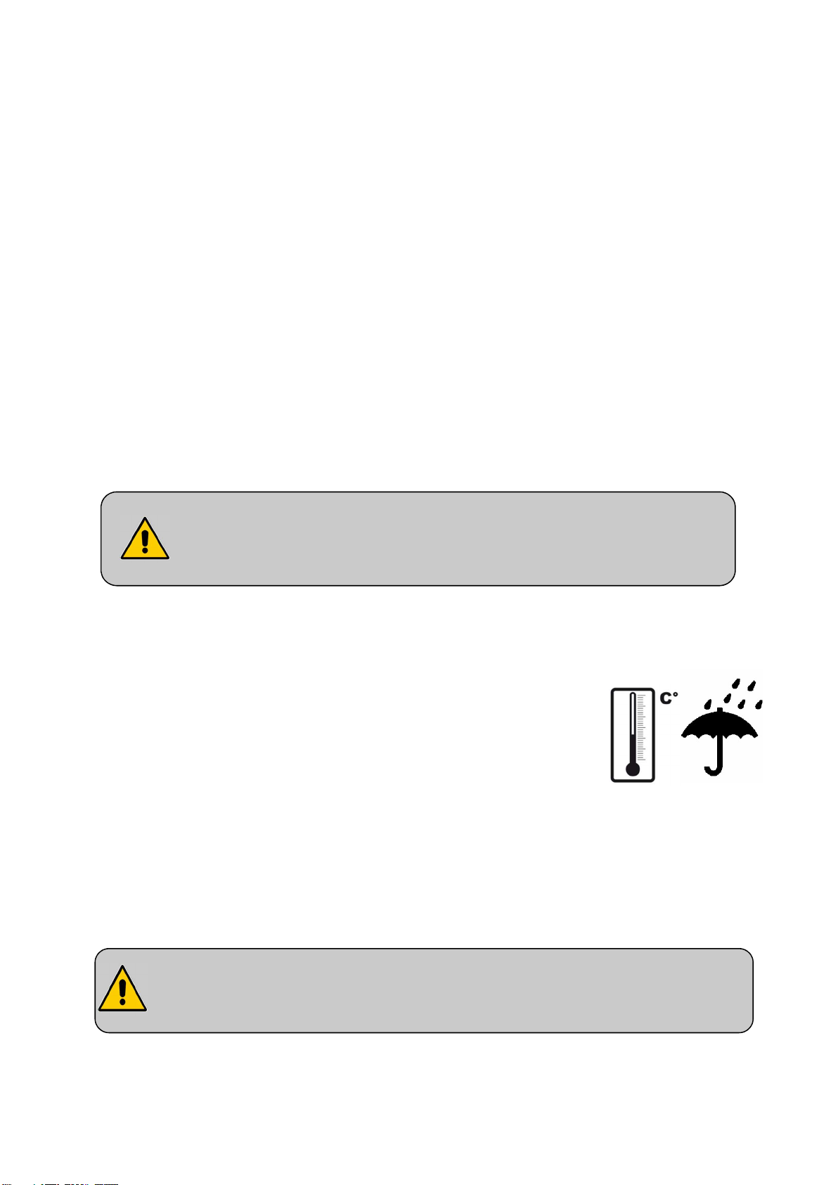
2. BED ENVIRONMENT CONDITIONS
The bed, along with the boards and accessories, must be transported and stored
at a room temperature of between -10°C and +50°C,
The bed, along with the boards and accessories, must used at a room
temperature of between +10°C and +40°C,
Relative humidity of between 30% and 75%.
Atmospheric pressure between 700hPa and 1060hPa
Observe the specified
environmental conditions
3. GENERAL USE
3.1. Precautions for use
Before use, it is essential to read these instructions carefully. They contain advice on using and looking after
the bed to guarantee optimum safety.
The user and staff must be trained and aware of the risks associated with
using the bed. He must not allow it by children and be vigilant when used by
confused or disoriented people.
4

Although the bed is conforming with Electromagnetic Compatibility, some devices may alter how it functions,
in which case they must be used at a distance or not used at all.
The bed is a medical device and must not be modified under any circumstances. You must ensure its
traceability, including that of the boards and its accessories.
If you are assembling medical devices not provided by the bed manufacturer, you must check the conformity
of the assembly and make the CE declaration of the new medical device.
The electric parts (jack, supply box, wired control, etc.) shall only be repaired by the manufacturer Linak.
The bed is not suitable for use with an inflammable anaesthetic mixture with air or oxygen or nitrous oxide.
The loads permitted (see bed characteristics) must be distributed evenly over the bed base.
Do not activate all the motors at the same time when the patient is in the bed (only one motor is authorised at
one time, except elevation by 2 motors or simultaneous function).
After each use and while care is being administered to the patient, the brakes must be activated.
We recommend putting the bed in its low position after every use and while the patient is resting, to reduce the
height of falls by a confused or agitated person. Remember to lock the function(s) (if the option is available).
On change of height or angle of the parts of the bed, make sure that there are no objects and no parts of the
patient’s or carer’s body caught between the bed, the boards, the accessories and the ground or between the
boards and base or between the cross braces.
Do not sit down on the side of the back rest or leg rest if this is not flat.
In the case of a prolonged more than 50 ° tilt bust semi-sitting position, it is recommended to vary the position
of the person in bed every 2 hours.
When the bed is being moved, keep the power lead well away from the ground and wheels.
When use of an adaptor, extension lead or connection plug proves necessary, you must check that its
characteristics are suitable for the bed.
Connection to the supply box must be done using a mains complying with the standards in force and
corresponding to a voltage of use of 230 V.
The mains plug must be disconnected before the bed is moved.
Do not pull on the mains leads to disconnect the mains plug.
During any handling, try not to catch the leads of the motors and remote control and do not get them knotted.
The wired control must be hooked to the headboard when not in use.
In the case of the use of infrared remote control(s), WINNCARE allows the establishment of a single bed in the
same room (or in a close environment) or a second bed only if the infrared options of 2 beds concerned are
different (I and I1).
The condition of the leads must be checked frequently. If the slightest modification is observed, the person in
charge for maintaining the bed must be contacted to carry out the necessary repairs.
If repairs are required, the person in charge of maintenance must be contacted.
For greater safety, some side rails can be adapted (see accessories).
Side rails should not be used to manipulate or move the medical bed.
To assist patient mobility, it is possible to fit a Mobility Aid System (S.A.M.).
For assistance, if necessary, in mounting, operation or maintenance or to report unexpected operation or
events, call your supplier or Winncare.
The cleaning instructions recommended must be complied with.
5
- Inform the patient and his visitors of the safety instructions to be ob
served.
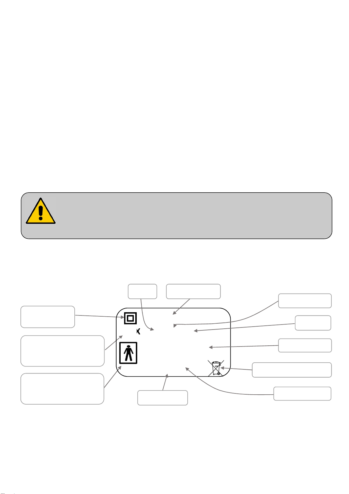
Classe II (double
insulation)
Operating time
IP XX
Xxx VA
Absorbed power
Only use original parts and accessories supplied by WINNCARE to guarantee safety and maintain product
conformity. The bed must not be modified.
Abnormal use of the bed may damage it or cause accidents to users, in which case the warranty shall be
annulled. Abnormal use means failure to comply with the precautions for use, maintenance instructions and
other uses not related to the bed’s normal purpose, such as: use of the bed by several people at the same time
(except DUO DIVISYS bed), use outdoors, moving the bed on a slope that is steeper than 10°, etc.
Put the bed in the designated room, foreseeing an appropriate perimeter of use for the different functions
(variable height, TR, etc.), especially if the bed has a lifting pole or side rails. Check that there is sufficient
ceiling height if a lifting pole is fitted.
Brake the wheels.
The mains socket should remain accessible to enable the bed to be disconnected quickly.
Plug in the power lead, checking that the mains comply with the standards in force and that it is suitable for the
supply box voltage.
Also ensure that the power lead, the remote control lead as well as the cables of possible other devices are
positioned correctly to prevent any risks of getting caught between the moving parts of the bed.
3.2. Electrical characteristics
Protection level against
dust and liquid penetration
Protection level against
electric shocks (type BF)
- Check that the bed operates properly after installing it in accordance with the check-list
appended in this document. (Test all of its functions)
- The patient is a planned operator of the bed. Users must be trained in how to use the
equipment.
3.2.1. Electrical data
Bed code Voltage
XXX-XXX-XXX
230V ~ 50 H
FACTEUR DE SERVICE :
xx% max. x min/xx min
PUISSANCE ABSORBEE :
ET-xxxxx
Sticker code
Z
In accordance with DEEE
Current type
Frequency
6
INDEX
console
console
control
2.5 m to 3 m, flow 100 l / min ± 5%).
TYPE
LINAK actuator
Supply box
Connection box
Operator’s side control
Operator’s mobile control
Wired control
Lockable wired control
Flexible arm control
Lockable and backlit wired
Battery
PROTECTION
LA27 / LA24 /
LA34 / LA40
CA40 / CB6 /
CB16 / CO61 / CO41
MJB IP 66 24V DC -
ACC IP 66 24V DC -
ACO IP 66 24V DC -
HB72 / HB74 IP 66 24V DC -
HL72 / HL74 IP 54 24V DC -
FPP IP 66 24V DC -
HB02X IP 66 24V DC -
BA1812- / BA21
IP 66 24V DC -
IP 66 230V AC 50 Hz
IP 66
VOLTAGE FREQUENCY
24V DC -
Infrared control
Night light
Keep dry
3.2.2. Protection level against dust and liquid penetration
Index
No protection.
0
Protected against solid bodies greater than
1
50 mm.
Protected against solid bodies greater than
2
12,5 mm.
Transmitter
HB21
Receiver IPX4
UBL IPX6 24V DC
3V DC -
Maximum operating time: Read the recommendations on the electrical label
on the bed.
1st number (decade)
Protection against solids
Protection against water intrusion
2nd number (unit)
No protection.
Protected against vertical drops of water drops.
Protected against falling drops of water up to 15°
from the vertical.
Protected against solid bodies greater than
3
2,5 mm.
Protected against solid bodies greater than
4
1 mm.
Protected against dust and other
5
microscopic residues.
Totally protected against dust. Protected against strong jets of water from all
6
Protected against rain water up to 60 ° from
vertical.
Protected against splashing water from all
directions.
Protected against jets of water from all directions at
the lance (6.3 mm nozzle, distance 2.5 m to 3 m,
flow 12.5 l / min ± 5%).
directions to the lance (12.5 mm nozzle, distance
7
NB:
UT
is the nominal value of power voltage applied during the test.
3.2.3. Electromagnetic compatibility
The bed will not move automatically when subject to electromagnetic disturbances within the limit of the values
indicated below.
Manufacturer’s declaration and guide – electromagnetic emissions
The medical bed (see references in contents) has been designed for use in the electromagnetic environment specified below. The user should ensure that it is used in such
Emissions test Compliance
RF emissions
CISPR 11
RF emissions
CISPR 11
Harmonic emissions
EN 61000-3-2
Voltage fluctuations / Flicker
EN 61000-3-3
RF emissions
CISPR 14-1
Group 1 The medical bed (see references in contents) uses RF energy only for its internal functions.
Class B
Class A
Applicable
Compliant The medical bed (see references in contents) has not been designed for connection to other
an environment.
ELECTROMAGNETIC ENVIRONMENT - GUIDE
Therefore, its RF emissions are very low and are not likely to cause any interference in nearby
electronic equipment.
The medical bed (see references in contents) can be used in all domestic environments, including those
directly connected to the public low-voltage power supply network that supplies buildings for domestic
purpose.
[ ]
equipment.
Manufacturer’s declaration and guide - electromagnetic immunity
The medical bed (see references in contents) has been designed for use in the electromagnetic environment specified below. The user should ensure that it is used in such
IMMUNITY TEST
Electrostatic discharge
EN 61000-4-2
Electrical fast transients
EN 61000-4-4
Surges
EN 61000-4-5
Voltage dips, short
interruptions and voltage
variations
EN 61000-4-11
Power frequency magnetic
field
(50/60 Hz)
IEC 60601
Severity level
6 kV contact
8 kV air
2 kV for feeders
1 kV for input/output lines
Differential mode 1 kV
Common mode 2 kV
<5% UT - for 10 ms
40% UT - for 100 ms
70% UT - for 500 ms
<5% UT - for 5 s
3 A/m 3 A/m Power frequency magnetic fields should be at levels characteristic of a location in
COMPLIANCE LEVEL ELECTROMAGNETIC ENVIRONMENT - GUIDE L
6 kV contact
8 kV air
2 kV for feeders
1 kV for input/output lines
Differential mode 1 kV
/
<5% UT – for 10 ms
40% U T - for 100 ms
70% UT - for 500 ms
<5% UT - for 5 s
an environment.
Floors should be wood, concrete, or ceramic tile. If floors are covered with
synthetic material, the relative humidity should be at least 30%.
The quality of the main power supply must be the same as for a typical
commercial or hospital environment.
The quality of the main power supply must be the same as for a typical
commercial or hospital environment.
The quality of the main power supply must be the same as for a typical
commercial or hospital environment.
If the user of the medical bed (see references in contents) wants to be
able to continue to use the bed during interruptions in the main power
supply, it is recommended that the bed be powered by a converter or
battery.
a typical commercial or hospital environment.
The medical bed (see references in contents) has been designed for use in the electromagnetic environment specified below. The user should ensure that it is used in such
Immunity test
Portable and mobile RF communications equipment should be used no closer to the medical
Recommended separation distance
Conducted RF
EN 61000-4-6
IEC 60601
Severity level
3 Vrms
150 kHz to 80 MHz
Manufacturer’s declaration and guide - electromagnetic immunity
an environment.
COMPLIANCE LEVEL
3 V
bed (see references in contents), including leads, than the recommended separation
distance, calculated using equations applicable to the frequency of the transmitter.
150 kHz to 80 MHz
Pd 17,1
Electromagnetic environment - Guide
8
Radiated RF
EN 61000-4-3
3 V/m
80 MHz to 2.5 GHz
3 V/m
80 to 800 MHz
80 MHz to 800 MHz
Pd 17,1
800 MHz to 2.5 GHz
Pd 33,2
Note 1 At 80 MHz and 800 MHz, the upper frequency range applies.
Note 2 These guidelines may not apply in all situations. Electromagnetic propagation is affected by absorption and reflection from structures, objects and people.
A Field strengths from fixed transmitters, such as base stations for radio (cellular/cordless) telephones and land mobile radios, amateur radio, AM and FM radio broadcast
and TV broadcast cannot be predicted theoretically with accuracy. To assess the electromagnetic environment due to fixed RF transmitters, an electromagnetic site
survey should be considered. If the measured field strength in the location in which the medical bed (see references in contents) is used exceeds the applicable RF
compliance level above, the normal operation of the bed must be checked. If abnormal performance is observed, additional measures may be necessary, such as reorienting or relocating the medical bed.
B Over the frequency range 150 kHz to 80 MHz, field strengths should be less than 3 V/m.
Recommended separation distances between portable and mobile RF communications equipment and the medical bed (see references in contents)
The medical bed (see references in contents) is intended for use in the electromagnetic environment in which radiated RF disturbances are controlled. The user of the bed can help
prevent electromagnetic interference by maintaining a minimum distance between portable and mobile RF communications equipment (transmitters) and the bed as recommended
below, according to the maximum output power of the communications equipment.
SEPARATION DISTANCE ACCORDING TO FREQUENCY OF TRANSMITTER M
Rated maximum power of transmitter
W
2 to 2.5 GHz
10 V/m
800 MHz to
2 GHz
150 kHz to 80 MHz 80 MHz to 800 MHz 800 MHz to 2.5 GHz
Pd 17,1
where P is the maximum output power rating of the transmitter in watts (W) according to
the transmitter manufacturer and d the recommended separation distance in meters (m).
The field strengths transmitted by fixed RF transmitters, determined by an electromagnetic
measurement of the site a, must be less than the conformity level in each range of
frequencies.
Disturbances can occur near devices marked with this symbol:
Pd 17,1
Pd 33,2
0.01
0.1 0.37 / 0.316 0.37 / 0.366 0.74 / 0.736
1 1.17 / 1.16 1.17 / 1.16 2.33 / 2.33
10 3.70 / 3.66 3.70 / 3.66 7.37 / 7.36
100 11.70 / 11.6 11.70 / 11.6 23.30 / 23.3
For transmitters rated at a maximum output power not listed above, the recommended separation distance d in meters (m) can be estimated using the equation applicable to the
frequency of the transmitter, where P is the maximum output power rating of the transmitter in watts (W) according to the transmitter manufacturer.
Note 1 At 80 MHz and 800 MHz, the separation distance for the higher frequency range applies.
Note 2 These guidelines may not apply in all situations. Electromagnetic propagation is affected by absorption and reflection from structures, objects and people.
0.12 / 0.116
0.12 / 0.116 0.23 / 0.233
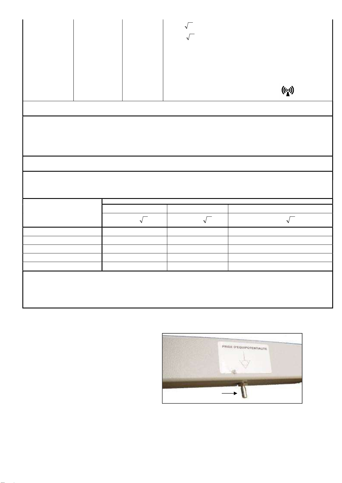
3.2.4. Equipotentiality
Under the head-half of the bed base
you will find an equipotentiality socket ,
Label
identified by the label , enabling you to
connect any electromedical devices.
The leads of these devices must
pass through the head end and
not the sides.
Equipotentiality
9
Width of base in cm
Ch
aract
e
risti
cs of compatible mattresses
Item
Width 120
Width 140
Width 160
WINNEA
P322
-00 - -
MEDIDOM II ELEGANT (2)
-
P324
-00
P325
-00
Auzence II
P612
-00
P613
-00
P614
-00
CARMEN II
with wooden barriers
(2) P621
-00
P622
-00
P623
-00
ABELIA II
Aluminum side rails
(1) P640
-00
P643
-00 -
STYLVIA
Aluminum side rails
(1) P641
-00
P644
-00 -
4. BED BOARDS 120/140/160cm WIDTH COMPATIBLE
MEDIDOM II (2) P319-00 P320-00 P321-00
Louis Philippe (1)(2) P416-00 P417-00 P418-00
Abélia II P617-00 P618-00 P619-00
CARMEN II P626-00 P627-00 P628-00
NOVIDA Aluminum side rails (1) P642-00 P645-00 -
(1) Bed board incompatible with the XPRESS transport kit
(2) Long pan option incompatible with the XPRESS transport kit
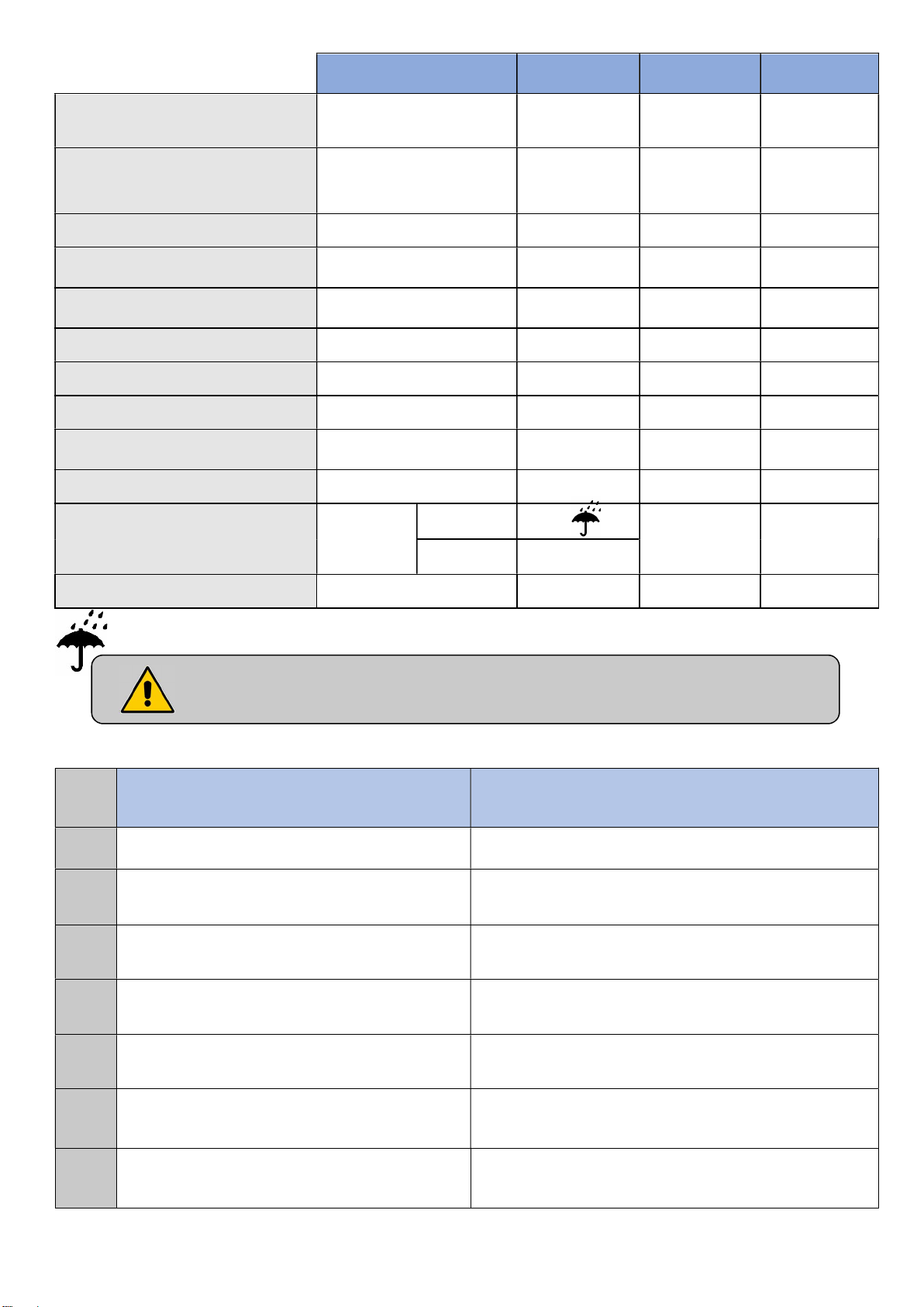
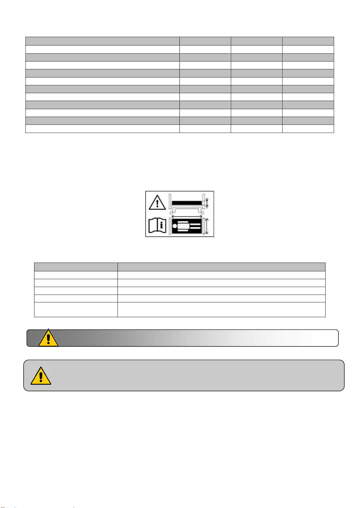
Mattress
Observe the mattress dimensions prescribed. See user guide
120
140
140 DUO
160 DUO
160 DUO option V 1x Width 68 cm minimum + 1x Width 88 cm minimum, with a high
There must be at least 220 mm between the top of the side rail and uncompressed and no
therapeutic mattress surface. It will be advisable to tend towards this specification in the case
of the use of a therapeutic mattress.
Width 116 cm minimum with a high resilience foam of 34Kg/m³ minimum
Width 136 cm minimum with a high resilience foam of 34Kg/m³ minimum
Width 68 cm minimum with a high resilience foam of 27Kg/m³ minimum
Width 78 cm minimum with a high resilience foam of 27Kg/m³ minimum
resilience foam of 27Kg/m³ minimum
Incompatible mattresses can pose RISKS.
10
 Loading...