

Winmate W07IB3S-POT1, W10IB3S-POA1, R15IB3S-POC3, R19IB3S-POM1, W22IB3S-POA3 Quick Start Manual [en, fr]
...Page 1
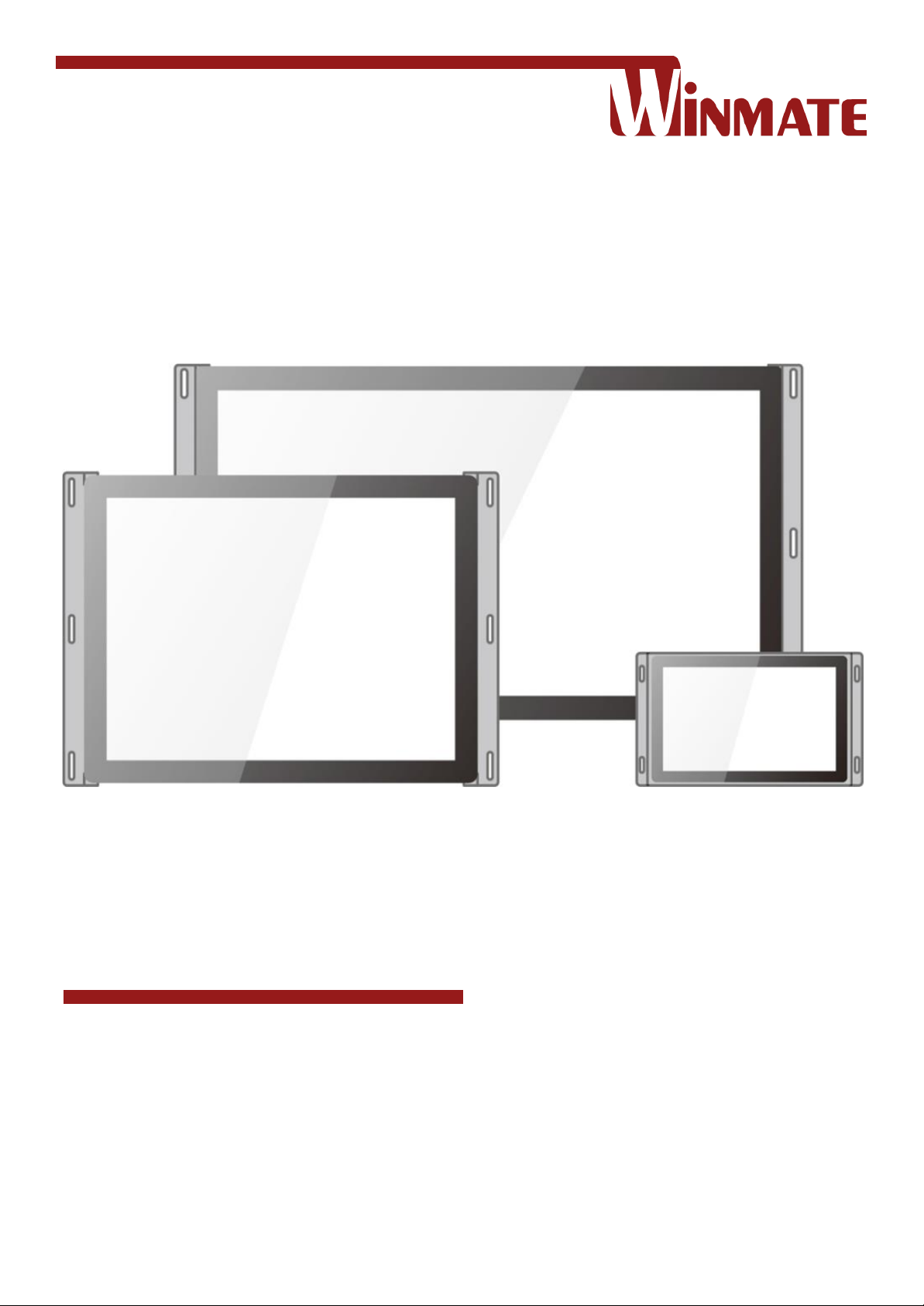
7~23.8”
P-Cap Open Frame Panel PC
Intel® Celeron® Bay Trail-M N2930 1.83 GHz
Model No. W07IB3S-POT1
W10IB3S-POA1
R15IB3S-POC3
W15IB3S-POA4
R19IB3S-POM1
W22IB3S-POA3
W24IB3S-POA2
Quick Start Guide
Document Version 1.2
Document Part No. 9152111I102J
Please read this instructions before operating the device and retain them for future reference.
Page 2

2
7~23.8" P-Cap Open Frame Panel PC Quick Start Guide
Contents
Preface ...................................................................................................................... 3
Chapter 1: Introduction ........................................................................................... 6
1.1 Product Features .................................................................................................. 6
1.2 Package Contents ................................................................................................ 6
1.3 Product Overview ................................................................................................. 7
Chapter 2: Mounting .............................................................................................. 11
2.1 Wall Mount ......................................................................................................... 11
Chapter 3: Installation ........................................................................................... 12
3.1 Cable Mounting Considerations ......................................................................... 12
3.2 Wiring Requirements .......................................................................................... 12
3.3 Connecting Power .............................................................................................. 13
3.4 Connecting to Other Devices ............................................................................. 13
3.4.1 Power Input Connector ............................................................................. 13
3.4.2 Serial Port Connector ............................................................................... 14
3.4.3 RJ-45 Connector ...................................................................................... 14
3.4.4 USB 2.0 & USB 3.0 Connector ................................................................. 14
3.4.5 HDMI Connector ....................................................................................... 14
Chapter 4: Operating the Device .......................................................................... 15
4.1 Operating System ............................................................................................... 15
4.2 How to Enable Watchdog ................................................................................... 15
4.3 Using Recovery Wizard to Restore Computer .................................................... 16
Chapter 5: Product Specifications ....................................................................... 17
Chapter 6: Technical Support ............................................................................... 19
Page 3

3
Preface
Preface
Copyright Notice
No part of this document may be reproduced, copied, translated, or transmitted in any form or by
any means, electronic or mechanical, for any purpose, without the prior written permission of the
original manufacturer.
Trademark Acknowledgement
Brand and product names are trademarks or registered trademarks of their respective owners.
Disclaimer
We reserve the right to make changes, without notice, to any product, including circuits and/or
software described or contained in this manual in order to improve design and/or performance. We
assume no responsibility or liability for the use of the described product(s) conveys no license or
title under any patent, copyright, or masks work rights to these products, and make no
representations or warranties that these products are free from patent, copyright, or mask work
right infringement, unless otherwise specified. Applications that are described in this manual are
for illustration purposes only. We make no representation or guarantee that such application will be
suitable for the specified use without further testing or modification.
Warranty
Our warranty guarantees that each of its products will be free from material and workmanship
defects for a period of one year from the invoice date. If the customer discovers a defect, we will,
at his/her option, repair or replace the defective product at no charge to the customer, provide it is
returned during the warranty period of one year, with transportation charges prepaid. The returned
product must be properly packaged in its original packaging to obtain warranty service. If the serial
number and the product shipping data differ by over 30 days, the in-warranty service will be made
according to the shipping date. In the serial numbers the third and fourth two digits give the year of
manufacture, and the fifth digit means the month (e. g., with A for October, B for November and C
for December).
For example, the serial number 1W16Axxxxxxxx means October of year 2016.
Customer Service
We provide a service guide for any problem by the following steps: First, visit the website of our
distributor to find the update information about the product. Second, contact with your distributor,
sales representative, or our customer service center for technical support if you need additional
assistance.
You may need the following information ready before you call:
Product serial number
Software (OS, version, application software, etc.)
Description of complete problem
The exact wording of any error messages
In addition, free technical support is available from our engineers every business day. We are
always ready to give advice on application requirements or specific information on the installation
and operation of any of our products.
Page 4
4
7~23.8" P-Cap Open Frame Panel PC Quick Start Guide
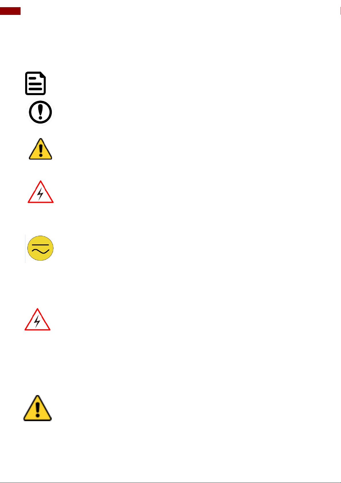
NOTE:
A note is used to emphasize helpful information
IMPORTANT:
An important note indicates information that is important for you to know.
CAUTION/ ATTENTION
A Caution alert indicates potential damage to hardware and explains how to
avoid the potential problem.
Unealerted’ attention indique un dommage possible à l’équipement et explique
comment éviter le problem potentiel.
WARNING!/AVERTISSEMENT!
An Electrical Shock Warning indicates the potential harm from electrical
hazards and how to avoid the potential problem.
Un Avertissement de Choc Électriqueindique le potentiel de chocssur des
emplacements électriques et comment éviterces problèmes.
ALTERNATING CURRENT / MISE À LE TERRE!
The Protective Conductor Terminal (Earth Ground) symbol indicates the
potential risk of serious electrical shock due to improper grounding.
Le symbole de Miseà Terre indique le risqué potential de choc électrique grave
à la terre incorrecte.
WARNING! / AVERTISSEMENT!
Always completely disconnect the power cord from your chassis whenever you
work with the hardware. Do not make connections while the power is on. Sensitive
electronic components can be damaged by sudden power surges. Only
experienced electronics personnel should open the PC chassis.
Toujours débrancher le cordon d’alimentation du chassis lorsque vous travaillez sur
celui-ci. Ne pas brancher de connections lorsque l’alimentation est présente. Des
composantes électroniques sensibles peuvent être endommagées par des sauts
d’alimentation. Seulement du personnel expérimenté devrait ouvrir ces chassis.
CAUTION/ATTENTION
Always ground yourself to remove any static charge before touching the CPU card.
Modern electronic devices are very sensitive to static electric charges. As a safety
precaution, use a grounding wrist strap at all times. Place all electronic components
in a static-dissipative surface or static-shielded bag when they are not in the
chassis.
Toujours verifier votre mise à la terre afin d’éliminer toute charge statique avant de
toucher la carte CPU. Les équipements électroniques moderns sont très sensibles
aux décharges d’électricité statique. Toujours utiliser un bracelet de mise à la terre
comme précaution. Placer toutes les composantes électroniques sur une surface
conçue pour dissiper les charge, ou dans un sac anti-statique lorsqu’elles ne sont
pas dans le chassis.
Advisory Conventions
Four types of advisories are used throughout the user manual to provide helpful information or to
alert you to the potential for hardware damage or personal injury. These are Notes, Important,
Cautions, and Warnings. The following is an example of each type of advisory.
Important Information
Page 5
5
Preface
CAUTION/ATTENTION
Do not cover the openings!
CAUTION
Always ground yourself to remove any static charge before
touching the board. Modern electronic devices are very
sensitive to static electric charges. As a safety precaution, use
a grounding wrist strap at all times. Place all electronic
components in a static-dissipative surface or static-shielded
bag when they are not in the chassis.
NOTE:
Some pictures in this guide are samples and can differ from actual product.
Safety Precautions
For your safety carefully read all the safety instructions before using the device. Keep this user
manual for future reference.
Always disconnect this equipment from any AC outlet before cleaning. Do not use liquid or
spray detergents for cleaning. Use a damp cloth.
For pluggable equipment, the power outlet must be installed near the equipment and must
be easily accessible.
Keep this equipment away from humidity.
Put this equipment on a reliable surface during installation. Dropping it or letting it fall could
cause damage.
The openings on the enclosure are for air convection and to protect the equipment from
overheating.
Before connecting the equipment to the power outlet make sure the voltage of the power
source is correct.
Position the power cord so that people cannot step on it. Do not place anything over the
power cord.
If the equipment is not used for a long time, disconnect it from the power source to avoid
damage by transient over-voltage.
Never pour any liquid into an opening. This could cause fire or electrical shock.
Never open the equipment. For safety reasons, only qualified service personnel should open
the equipment.
All cautions and warnings on the equipment should be noted.
Page 6
6
7~23.8" P-Cap Open Frame Panel PC Quick Start Guide
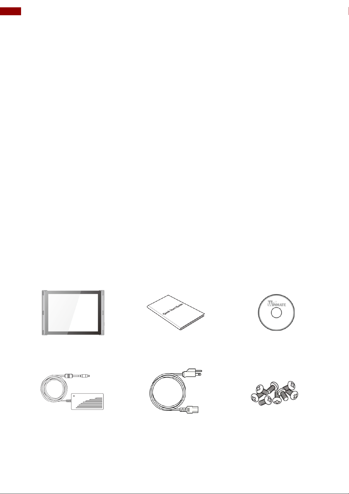
Panel PC
Quick Start Guide
(Hardcopy)
Driver CD
Varies by product specifications
Part No. 9152111I102J
Part No.9171111I103M
AC Adapter(12V/ 50W)
Power Cable
Black Screw Bolts*
Part No.922D050W12VA
Varies by country
Varies by product
Chapter 1: Introduction
Congratulations on purchasing Winmate® P-Cap Open Frame Panel PC. Versatile panel PC in an
open-frame housing designed for rear and VESA mounting with integrated bracket design for
KIOSK applications. The Winmate P-Cap Open Frame Panel PC is a microprocessor-controlled
computer that runs on Intel® Celeron® Bay Trail-M N2930 processor and has 7”, 10.1”, 15” and
21.5” screen size. Panel PC feature all necessary connectors, USB 3.0 and USB 2.0, serial port,
HDMI and two RJ-45 Ethernet ports. It is designed to meet the demanding performance
requirements of today’s business and industrial applications.
1.1 Product Features
Winmate® P-Cap Open Frame Panel PC features:
7”, 10.1”, 15”, 15.6”, 19”, 21.5” and 23.8” screen size
Intel® Celeron® Bay Trail-M N2930 1.83 GHz
Slim-line design in open-frame housing
Multi Touch P-Cap flat design
Windows 8.1 /10 IoT system
12V DC input with power jack
Wall mount
Suitable for KIOSK applications
1.2 Package Contents
Carefully remove the box and unpack your Panel PC. Please check if all the items listed below are
inside your package. If any of these items are missing or damaged contact us immediately.
Standard factory shipment list:
*Notice: Screw bolts provided by Winmate only to be used to screw the panel PC onto a console
from the rear side. If you prefer your own bolts, please make sure to use M4 and 30mm in length
Page 7
7
Chapter 1: Introduction
№
Description
№
Description
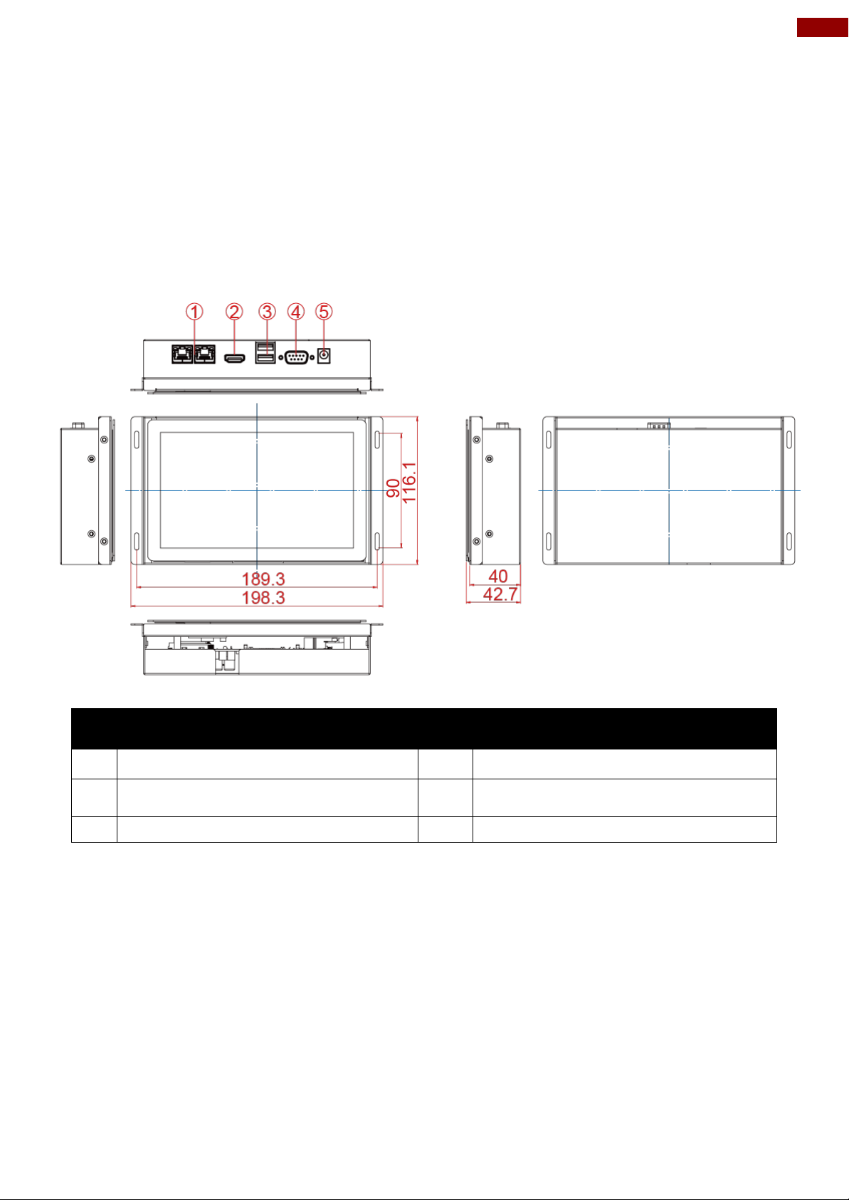
RJ-45 (LAN) x 2
RS-232/422/485
HDMI
12V DC IN Power Jack
USB 2.0 x 1, USB 3.0 x 1
1.3 Product Overview
This section describes physical appearance of the P-Cap Open Frame Panel PC.
Notice that input and output connectors vary by product size and specifications. The picture above
shows only a prototype model for information purposes only.
7”, W07IB3S-POT1
Unit: mm
Dimensions: 198.3 x 116.1 x 42.7
Page 8
8
7~23.8" P-Cap Open Frame Panel PC Quick Start Guide
№
Description
№
Description
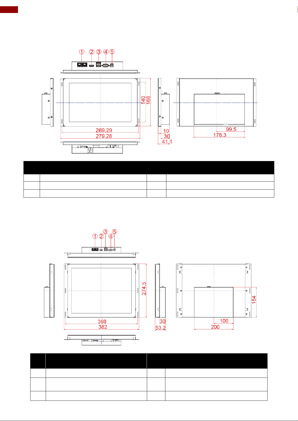
RJ-45 (LAN) x 2
RS-232/422/485
HDMI
12V DC IN Power Jack
USB 2.0 x 1, USB 3.0 x 1
№
Description
№
Description
RJ-45 (LAN) x 2
RS-232/422/485
HDMI
12V DC IN Power Jack
USB 2.0 x 1, USB 3.0 x 1
10.1”, W10IB3S-POA1
Unit: mm
Dimensions:279.28 x 168 x 41.1
15”, R15IB3S-POC3
Unit: mm
Dimensions:382 x 274.5 x 53.2
Page 9
9
Chapter 1: Introduction
№
Description
№
Description
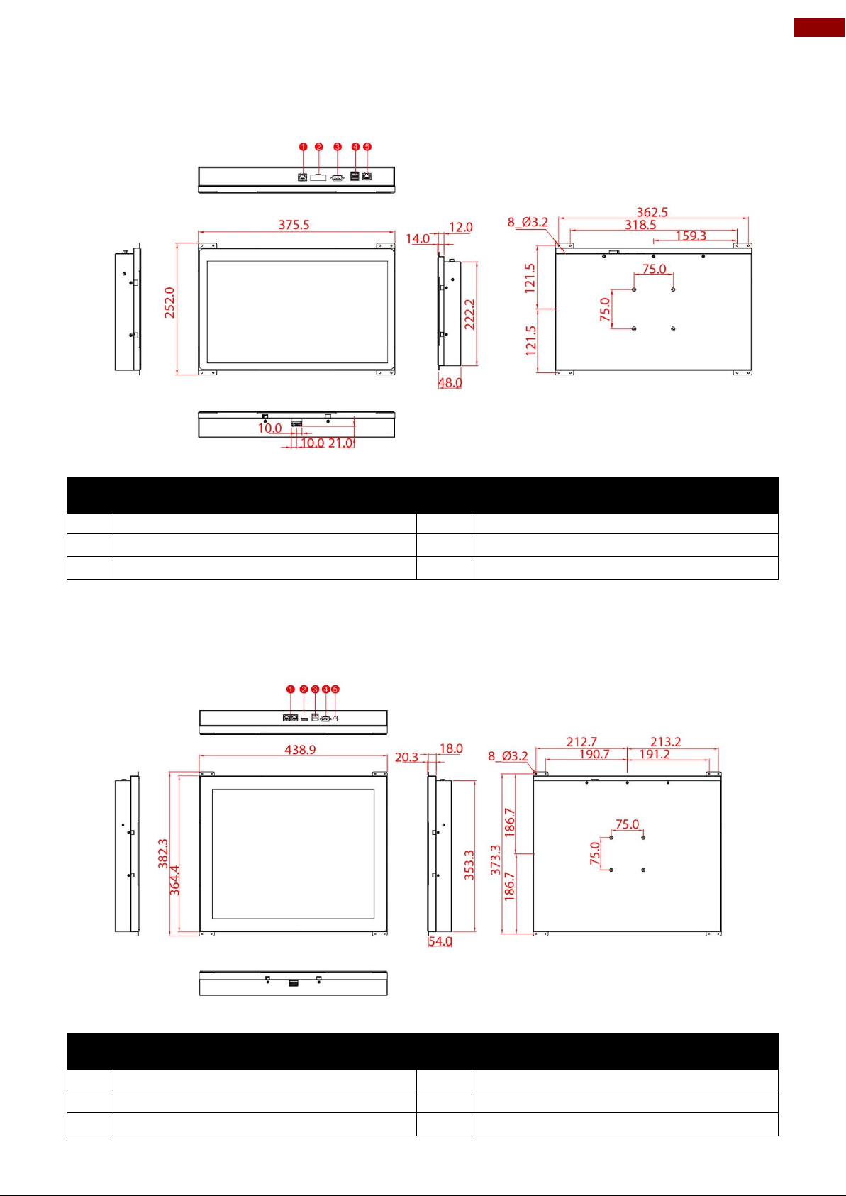
RJ-45 (LAN) x 2
RS-232/422/485
HDMI
12V DC IN Power Jack
USB 2.0 x 1, USB 3.0 x 1
№
Description
№
Description
RJ-45 (LAN) x 2
RS-232/422/485
HDMI
12V DC IN Power Jack
USB 2.0 x 1, USB 3.0 x 1
15.6”, W15IB3S-POA4
Unit: mm
Dimensions:375.5 x 252 x 48
19”, R19IB3S-POM1
Unit: mm
Dimensions: 438.9 x 382.3 x 54
Page 10
10
7~23.8" P-Cap Open Frame Panel PC Quick Start Guide
№
Description
№
Description
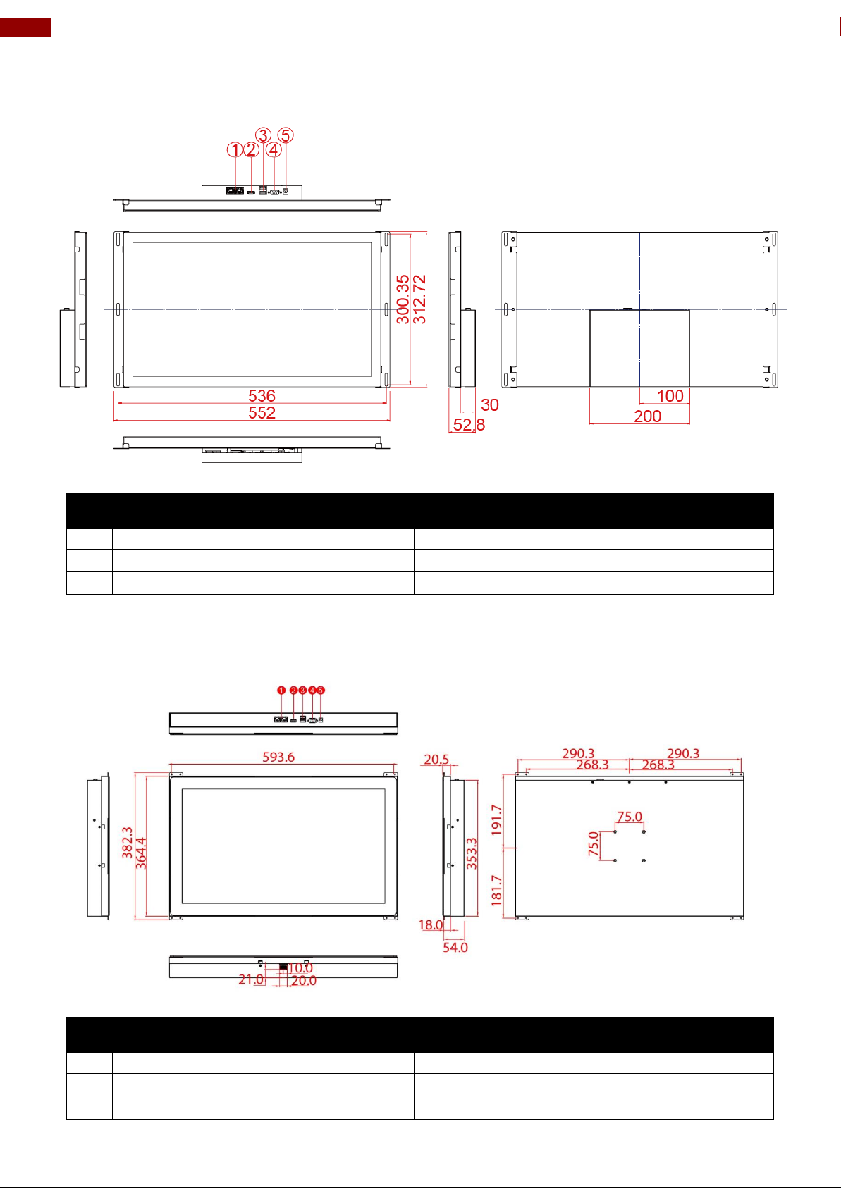
RJ-45 (LAN) x 2
RS-232/422/485
HDMI
12V DC IN Power Jack
USB 2.0 x 1, USB 3.0 x 1
№
Description
№
Description
RJ-45 (LAN) x 2
RS-232/422/485
HDMI
12V DC IN Power Jack
USB 2.0 x 1, USB 3.0 x 1
21.5”, W22IB3S-POA3
Unit: mm
Dimensions:552 x 312.72 x 52.8
23.8”, W24IB3S-POA2
Unit: mm
Dimensions:593.6 x 382.3x 54
Page 11
11
Chapter 2: Mounting
WARNING! / AVERTISSEMENT!
Follow mounting instructions and use recommended mounting hardware to
avoid the risk of injury.
Suivez les instructions de montage et d'utilisation recommandé le matériel
de montage pour éviter le risque de blessure.
CAUTION/ ATTENTION
Follow mounting instructions and use recommended mounting hardware to
avoid the risk of injury.
Suivez les instructions de montage et d'utilisation recommandé le matériel
de montage pour éviter le risque de blessure.
❶ ❷
❸ ❹
Chapter 2: Mounting
This chapter provides mounting guide for all available mounting options. Pay attention to cautions
and warning to avoid any damages.
2.1 Wall Mount
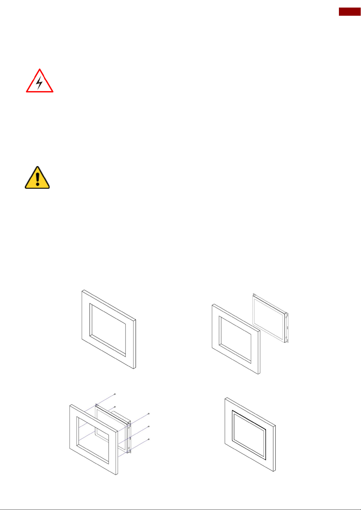
The Open Frame Panel PC supports open frame wall mount that enables you to install the unit
onto a wall (where space has been cut out to accommodate the rest of the hardware).
Installation Instruction
1. Make a cutout on the fixture (ex. wall) according to the cutout dimensions of the panel PC.
2. Based on the drawing, mark screw holes on the rear side of the fixture. Place panel PC on
the fixture from the rear side.
3. Use electric screwdriver to fasten M3 screws from the rear side.
4. You complete the installation. Please connect all the peripherals if needed.
Page 12

12
7~23.8" P-Cap Open Frame Panel PC Quick Start Guide
WARNING! / AVERTISSEMENT!
Observe all local installation requirements for connection cable type and
protection level.
Suivre tous les règlements locaux d’installations, de câblage et niveaux de
protection.
WARNING! / AVERTISSEMENT!
Turn off the device and disconnect other peripherals before installation.
Éteindre l’appareil et débrancher tous les périphériques avant l’installation
ALTERNATING CURRENT / MISE À LE TERRE!
To prevent electrical shock, the Safety Ground location on the rear must be
bonded to the local earth ground through a minimum 12 AWG wire as short as
possible.
Pour éviter les chocs électriques, l’emplacement de la prise terre à l’arrière
doit être lié à terre locale, à travers un 12 AWG minimum et aussi court que
possible.
Chapter 3: Installation
This chapter provides hardware installation instructions and mounting guide for all available
mounting options. Pay attention to cautions and warning to avoid any damages.
3.1 Cable Mounting Considerations
For a nice look and safe installation, make sure cables are neatly hidden behind the device.
3.2 Wiring Requirements
The following common safety precautions should be observed before installing any electronic
device:
Strive to use separate, non-intersecting paths to route power and networking wires. If power
wiring and device wiring paths must cross make sure the wires are perpendicular at the
intersection point.
Keep the wires separated according to interface. The rule of thumb is that wiring that shares
similar electrical characteristics may be bundled together.
Do not bundle input wiring with output wiring. Keep them separate.
When necessary, it is strongly advised that you label wiring to all devices in the system.
Do not run signal or communication wiring and power wiring in the same conduit. To avoid
interference, wires with different signal characteristics (i.e., different interfaces) should be
routed separately.
Be sure to disconnect the power cord before installing and/or wiring your device.
Verify the maximum possible current for each wire gauge, especially for the power cords.
Observe all electrical codes dictating the maximum current allowable for each wire gauge.
If the current goes above the maximum ratings, the wiring could overheat, causing serious
damage to your equipment.
Be careful when handling the unit. When the unit is plugged in, the internal components generate
a lot of heat which may leave the outer casing too hot to touch.
Page 13
13
Chapter 3: Installation
CAUTION
Use only the AC adapter included in your package
(Rating: Output 4.2 A). Using other AC adapters may damage the
device.
Pin №
Signal Name
1
12V
2
GND
Voltage
Minimum Voltage 11.4V
Maximum Voltage 12.6V
Maximum Current 4.2A
3.3 Connecting Power
This section provides information on how to use connectors on the P-Cap Open Frame Panel PC.
Notice that connectors are located on the top rear side of the device. Be cautious while working
with these modules. Please carefully read the content of this chapter in order to avoid any
damages.
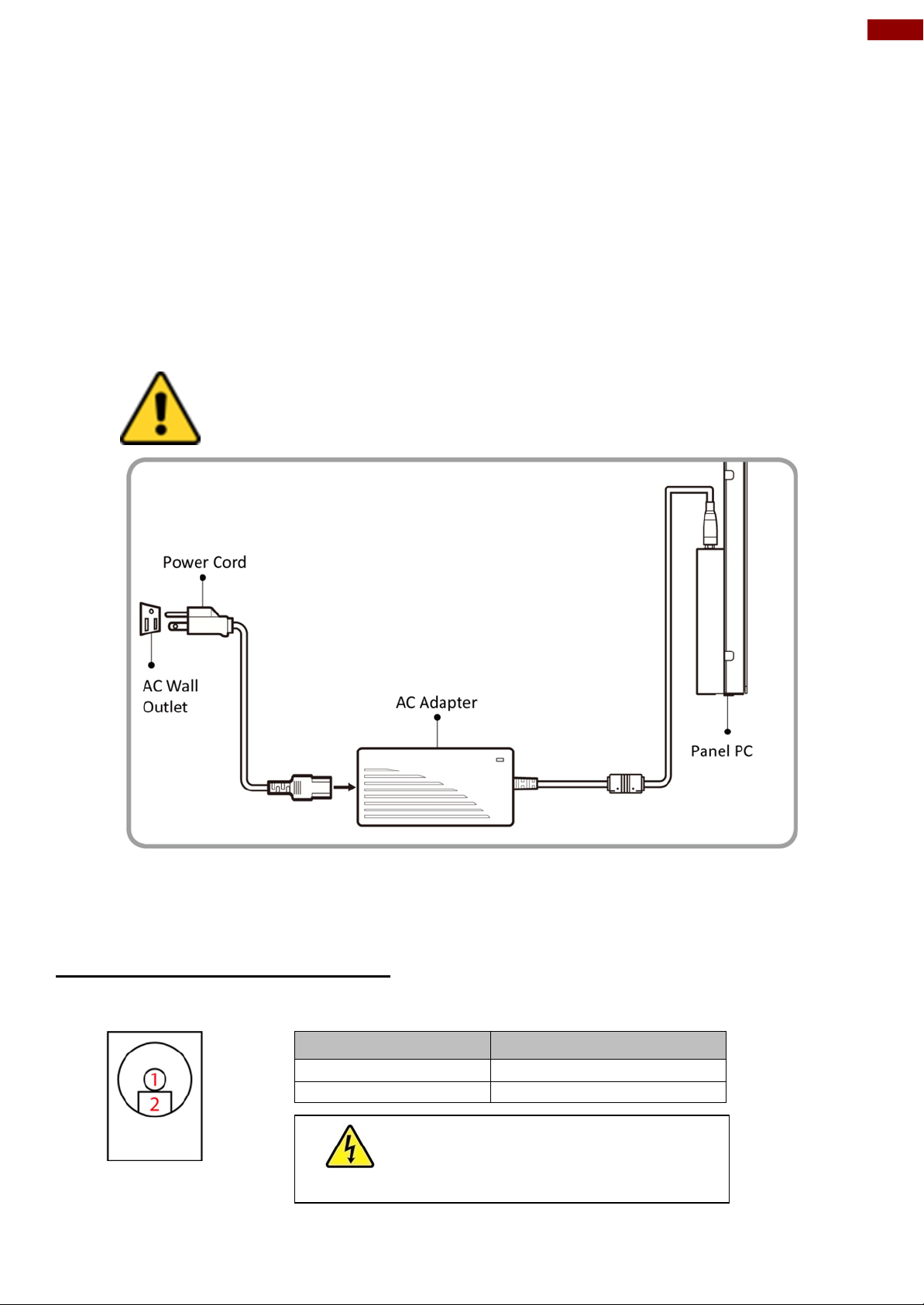
Installation instruction:
1. Connect the Panel PC to a power jack.
2. Connect the other side of the thermal block to the AC adapter.
3. Connect the AC adapter to the power cord.
4. Plug in the power cord to a working AC wall outlet. The device will boot automatically.
3.4 Connecting to Other Devices
This section explains how to connect external interfaces to the Panel PC.
3.4.1 Power Input Connector
DC power source input is a power jack connector. Power Input is 12V DC in.
Page 14
14
7~23.8" P-Cap Open Frame Panel PC Quick Start Guide
Pin №
RS232
RS422
RS485
1
DCD
TxD-
D-
2
RXD
TxD+
D+
3
TXD
RxD+
NC
4
DTR
RxD-
NC
5
GND
GND
GND
6
DSR
NC
NC
7
RTS
NC
NC
8
CTS
NC
NC
9
RI
NC
NC
Pin №
Signal Name
Pin №
Signal Name
1
TX1+
2
TX1-
3
TX2+
4
TX2-
5
TX3+
6
TX3-
7
TX4+
8
TX4-
Pin №
Signal Name
Pin №
Signal Name
1
+5V
2
USB_D-
3
USB_D+
4
GND
5
STDA_SSRX-
6
STDA_SSRX+
7
GND_DRAIN
8
STDA_SSTX-
9
STDA_SSTX+
10
+5V
11
USB_D-
12
USB_D+
13
GND
Pin №
Signal Name
Pin №
Signal Name
1
TMDS_DATA2+
2
GND
3
TMDS_DATA2-
4
TMDS_DATA1+
5
GND
6
TMDS_DATA1-
7
TMDS_DATA0+
8
GND
9
TMDS_DATA0-
10
TMDS_CLOCK+
11
GND
12
TMDS_CLOCK-
13
CEC
14
NC
15
DDC_CLOCK
16
DDC_DATA
17
GND
18
5V
19
Hot Plug Detect
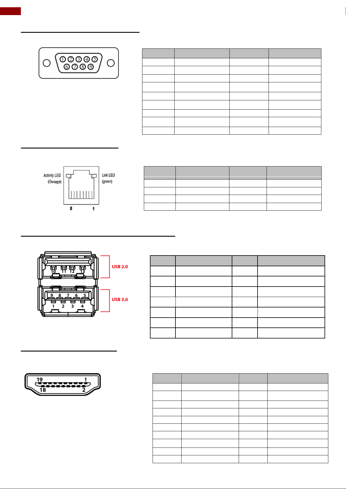
3.4.2 Serial Port Connector
Use serial port to connect your panel PC to external devices such as mouse, modem or printer.
Refer to User Manual for instructions on
how to configure serial port settings.
3.4.3 RJ-45 Connector
The panel PC has one RJ45 10/100/1000 Mbps Ethernet interface for connecting to the internet.
3.4.4 USB 2.0 & USB 3.0 Connector
Use USB connector to connect your panel PC to other USB 2.0/ USB3.0 compatible devices.
3.4.5 HDMI Connector
Use HDMI connector to connect your Panel PC to external display.
Page 15
15
Chapter 4: Operating the Device
IMPORTANT:
The device is shipped with the OS System according to your order. Contact
us if you have any questions regarding OS settings.
Chapter 4: Operating the Device
In this chapter you will find instructions on how to operate the Panel PC.
4.1 Operating System
P-Cap Open Frame Panel PC support several versions of Windows OS: Windows 10 IoT,
Windows Embedded 8 Standard, Windows 7 Pro for Embedded Systems, and Windows
Embedded Standard 7– WS7P.
4.2 How to Enable Watchdog
To enable Watchdog, you need to download Winmate Watchdog utility. Find more information on
Watchdog in “Watchdog Guide” that you can download from Winmate Download Center. Refer to
the User Manual for more details.
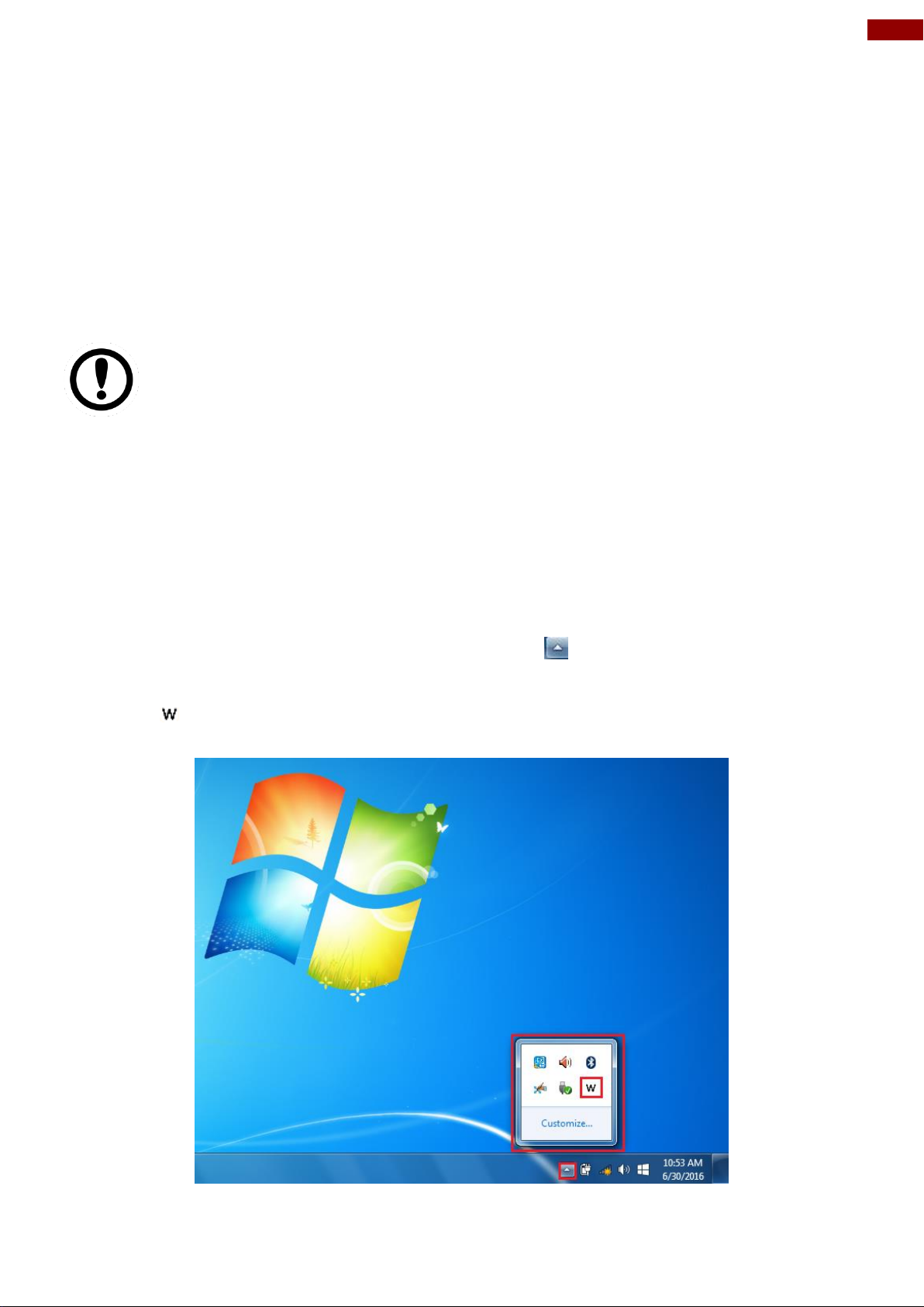
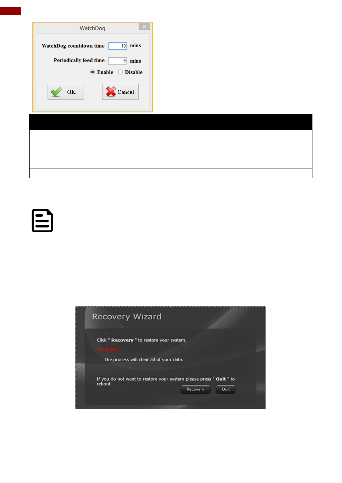
To enable watchdog in Watchdog AP follow the instructions below:
1. On the right bottom side of the desktop screen, click triangle button to show hidden
icons.
2. Click icon to open Watchdog utility.
3. In Watchdog utility window set countdown time and periodically feed time, or disable
watchdog.
Page 16
16
7~23.8" P-Cap Open Frame Panel PC Quick Start Guide
Example:
Every 10 min watchdog will monitor the
system, in case any error occurs the system
will restart automatically when the countdown
time reaches 0.
Every 9 min watchdog timer will be reset to
10 min.
Settings
Description
Watchdog Countdown Time
The system automaticity restarts when this countdown
time reaches zero. Default: 10 min
Periodically Feed Time
To set a cycle time to automatically reset watchdog timer.
Default: 9 min
Enable / Disable
Enable or disable watchdog. Default: Enable
NOTE:
Before starting the recovery process, make sure to backup all user data. The
data will be lost after the recovery process.
4.3 Using Recovery Wizard to Restore Computer
To enable quick one-key recovery procedure:
1. Connect the computer to the power source. Make sure the computer stays plugged in to
power source during the recovery process.
2. Turn on the computer, and when the boot screen shows up, press Tab+ F6 to initiate the
Recovery Wizard.
3. The following screen shows the Recovery Wizard. Click Recovery button to continue.
4. A warning message about data loss will show up. Make sure the data is backed up before
recovery, and click Yes to continue.
Wait the recovery process to complete. During the recovery process, a command prompt will show
up to indicate the percent of recovery process complete. The system will restart automatically after
recovery complete.
Page 17
17
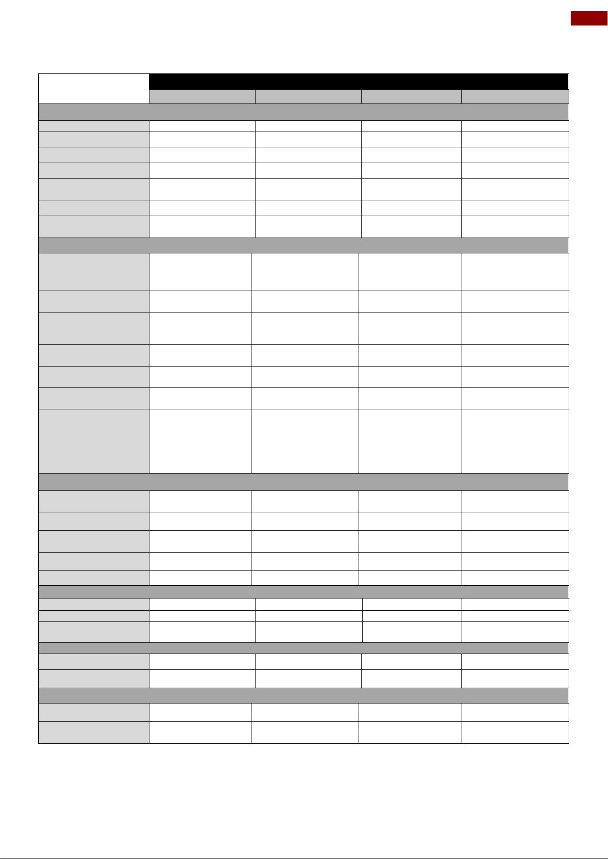
Chapter 5: Product Specifications
Model Name
W07IB3S-POT1
W10IB3S-POA1
R15IB3S-POC3
W15IB3S-POA4
Display
Size
7"
10.1"
15"
15.6"
Resolution
1024 x 600
1920 x 1200
1024 x 768
1920x1080
Brightness
500
700
250
300
Contrast Ratio
700:1 (typ.)
750:1 (typ.)
700:1 (typ.)
800:1 (typ.)
Viewing Angle
-75~75(H);
-70~75 (V)
-89~89(H);
-89~89(V)
- 80~80(H);-70~70(V)
-85~85(H);-85~85(V)
Max. Colors
16.7M (8 bit)
16.7M (8 bit)
16.7M (8 bit)
262K
Touch
P-Cap
P-Cap, AG Coating
(Optional)
P-Cap, AG
Coating(Optional)
P-Cap
System
Processor
Intel® Celeron® Bay
Trail-M N2930,
1.83GHz
Intel® Celeron® Bay
Trail-M N2930,
1.83GHz
Intel® Celeron® Bay
Trail-M
N2930,1.83GHz
Intel® Celeron® Bay
Trail-M N2930,
1.83GHz
System Chipset
Intel® ATOM SoC
Integrated
Intel® ATOM SoC
Integrated
Intel® ATOM SoC
Integrated
Intel® ATOM SoC
Integrated
Memory
SODIMM DDR3L
1600/1333, max. 8
GB
SODIMM DDR3L
1600/1333, max. 8 GB
SODIMM DDR3L
1600/1333, max. 8 GB
SODIMM DDR3L
1600/1333, max. 8 GB
Storage
mSATA SSD 64GB
(Default)
mSATA SSD 64GB
(Default)
mSATA SSD 64GB
(Default)
mSATA SSD 64GB
(Default)
LAN
Intel® I210-AT GbE
LAN x 2
Intel® I210-AT GbE
LAN x 2
Intel® I210-AT GbE
LAN x 2
Intel® I210-AT GbE
LAN x 2
Expansion Slot
Mini PCIe (1 for WiFi,
1 for 3G)
Mini PCIe (1 for WiFi, 1
for 3G)
Mini PCIe (1 for WiFi,
1 for 3G)
Mini PCIe (1 for WiFi, 1
for 3G)
OS
Windows 10 IoT
Enterprise
Windows 8
Embedded
Windows 7
Embedded
Windows 10 IoT
Enterprise
Windows 8 Embedded
Windows 7 Embedded
Windows 10 IoT
Enterprise
Windows 8 Embedded
Windows 7 Embedded
Windows 10 IoT
Enterprise
Windows 8 Embedded
Windows 7 Embedded
Input/ Output Connectors
Ethernet LAN
2 x RJ45-10/100/1000
Mbps (LAN)
2 x RJ45-10/100/1000
Mbps (LAN)
2 x RJ45-10/100/1000
Mbps (LAN)
2 x RJ45-10/100/1000
Mbps (LAN)
Serial Interface
1xRS232/422/485
1xRS232/422/485
1xRS232/422/485
1xRS232/422/485
USB
1 x USB 3.0,
1 x USB 2.0
1 x USB 3.0,
1 x USB 2.0
1 x USB 3.0,
1 x USB 2.0
1 x USB 3.0,
1 x USB 2.0
HDMI
1 x HDMI
1 x HDMI
1 x HDMI
1 x HDMI
Power
1 x Power Jack
1 x Power Jack
1 x Power Jack
1 x Power Jack
Mechanical Specifications
Cooling
Fanless design
Fanless design
Fanless design
Fanless design
Mounting
Wall Mount
Wall Mount
Wall Mount
Wall Mount
Dimensions, mm
198.3x116.1x42.7
279.28x168x41.1
350 x 292 x 48
382 x 274.5 x 53.2
Power Specifications
Power Input
12V DC
12V DC
12V DC
12V DC
Power Consumption
17W (typ.)
24W (typ.)
43W (typ.)
43W (typ.)
Environmental Consideration
Operating Temp.
0°C ~ +50°C
0°C ~ +50°C
0°C ~ +50°C
0°C ~ +50°C
Operating Humidity
10% ~ 90%(noncondensing, RH)
10% ~ 90% (noncondensing, RH)
10% ~90%(noncondensing,RH)
10% ~ 90%(noncondensing, RH)
Chapter 5: Product Specifications
Page 18
18
7~23.8" P-Cap Open Frame Panel PC Quick Start Guide
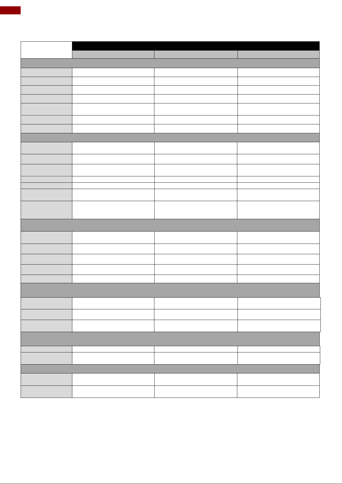
Model Name
R19IB3S-POM1
W22IB3S-POA3
W24IB3S-POA2
Display
Size
19"
21.5"
23.8”
Resolution
1280 x 1024
1920 x 1080
1920 x 1080
Brightness
250
250
250
Contrast Ratio
1000 : 1 (typ.)
1000:1 (typ.)
3000 : 1 (typ.)
Viewing Angle
-85~85(H);-80~80(V)
-89~89(H);
-89~89(V)
-89~89(H);
-89~89(V)
Max. Colors
16.7M (8 bit)
16.7M (8 bit)
16.7M (8 bit)
Touch
P-Cap, AG Coating (Optional)
P-Cap, AG Coating (Optional)
P-Cap
System
Processor
Intel® Celeron® Bay Trail-M
N2930, 1.83 GHz
Intel® Celeron® Bay Trail-M
N2930, 1.83 GHz
Intel® Celeron® Bay Trail-M
N2930, 1.83 GHz
System Chipset
Intel® ATOM SoC Integrated
Intel® ATOM SoC Integrated
Intel® ATOM SoC Integrated
Memory
SODIMM DDR3L 1600/1333,
max. 8 GB
SODIMM DDR3L 1600/1333,
max. 8 GB
SODIMM DDR3L 1600/1333,
max. 8 GB
Storage
mSATA SSD 64GB (Default)
mSATA SSD 64GB (Default)
mSATA SSD 64GB (Default)
LAN
Intel® I210-AT GbE LAN x 2
Intel® I210-AT GbE LAN x 2
Intel® I210-AT GbE LAN x 2
Expansion Slot
Mini PCIe (1 for WiFi, 1 for 3G
Module)
Mini PCIe (1 for WiFi, 1 for 3G
Module)
Mini PCIe (1 for WiFi, 1 for 3G
Module)
OS
Windows 10 IoT Enterprise
Windows 8 Embedded
Windows 7 Embedded
Windows 10 IoT Enterprise
Windows 8 Embedded
Windows 7 Embedded
Windows 10 IoT Enterprise
Windows 8 Embedded
Windows 7 Embedded
Input/ Output Connectors
Ethernet LAN
2 x RJ 45-10/100/1000 Mbps
(LAN)
2 x RJ 45-10/100/1000 Mbps
(LAN)
2 x RJ 45-10/100/1000 Mbps
(LAN)
Serial Interface
1 x RS232/422/485
1 x RS232/422/485
1 x RS232/422/485
USB
1 x USB 3.0, 1 x USB 2.0
1 x USB 3.0, 1 x USB 2.0
1 x USB 3.0, 1 x USB 2.0
HDMI
1 x HDMI
1 x HDMI
1 x HDMI
Power
1 x Power Jack
1 x Power Jack
1 x Power Jack
Mechanical Specifications
Cooling System
Fanless design
Fanless design
Fanless design
Mounting
Wall Mount
Wall Mount
Wall Mount
Dimensions, mm
438.9 x 382.3 x 54
552x312.72x52.8
593.6 x 382.3 x 54
Power Specifications
Power Input
12V DC
12V DC
12V DC
Power
Consumption
35W (typ.)
60W (typ.)
45W (typ.)
Environmental Consideration
Operating
Temperature
0°C ~ +50°C
0°C ~ +50°C
0°C ~ +50°C
Operating Humidity
10% ~ 90% (non-condensing,
RH)
10% ~ 90% (non-condensing,
RH)
10% ~ 90% (non-condensing,
RH)
Page 19

19
Chapter 6: Technical Support
Item
File Type
Description
1
SDK
Watchdog SDK
2
Utility
Watchdog Utility
Chapter 6: Technical Support
Winmate provides the following SDK and Utilities for Open Frame Panel PC with Intel® Celeron®
N2930:
To find the Drivers and SDK, please refer to the Driver CD that comes in the package or contact
us. Also, you can download drivers from Winmate Download Center.
Winmate Download Center
Go to http://www.winmate.com / > Support > Download Center > Panel PC > IB32
Or follow the link: http://www.winmate.com/DownCenter/DownLoadCenter.asp?DownType=0353
Page 20

Winmate Inc.
9F, No.111-6, Shing-De Rd., San-Chung District,
New Taipei City 24158, Taiwan, R.O.C
www.winmate.com
Copyright © Winmate Inc. All rights reserved.
 Loading...