

Page 1
Please read these instructions carefully before using this product, and save this manual for future use
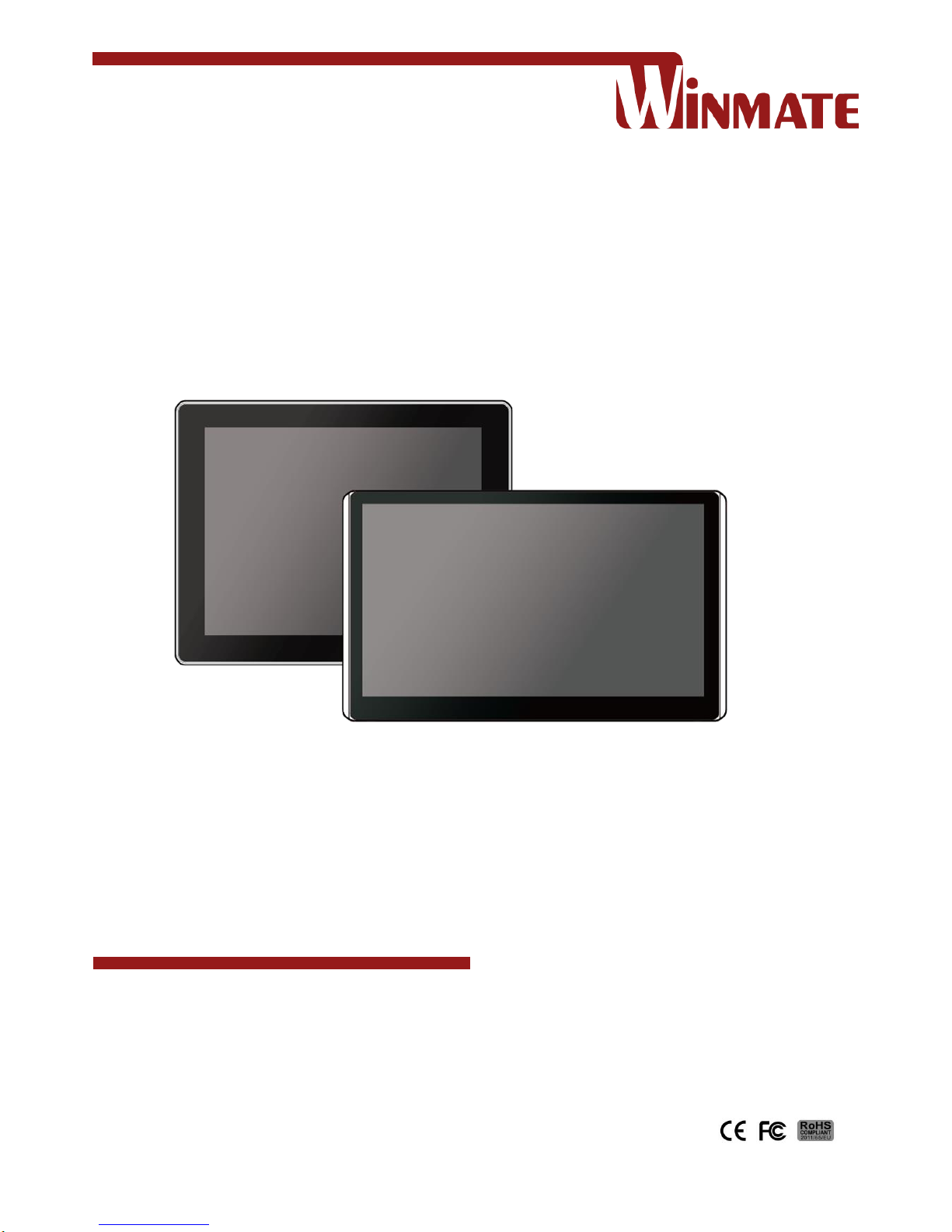
PT Series Multi-Touch
Chassis HMI
Freescale® Cortex A9 i.MX6 Dual Core, 1GHz
(Optional Quad Core)
Model No. R15FA3S-PTC3
W15FA3S-PTA3
User Guide
Part No. 91521110101V
Version 1.1
Page 2

2
PT Series Android HMI User Guide
Contents
Preface 4
Chapter 1: Introduction 8
1.1 Features 8
1.2 Package Contents 8
1.3 Mechanical Dimensions 9
1.4 Connector Description 10
1.5 Physical Buttons and LED Indicators 10
Chapter 2: Installation 11
2.1 Wiring Requirements 11
2.2 VESA Mounting 12
2.3 Turning On 13
2.4 Connecting Peripherals 14
2.4.1 Power Input Connector 14
2.4.2 Serial Port Connector 14
2.4.3 Ethernet Connector 14
2.4.4 USB 2.0 Connector 15
3.4.5 USB OTG Connector 15
3.4.6 Micro SD Card Slot 15
2.5 Speaker 16
Chapter 3: Operating the Device 17
3.1 Home Screen 17
3.2 Quick Settings 18
3.3 Configuring Serial Port Settings 20
3.4 Brightness Adjustment 22
3.5 Ethernet 23
3.5.1 Configuring Ethernet Settings 24
3.5.2 Configuring Ethernet 25
3.6 Winmate® Home Manager (WHM) 26
3.6.1 How to Lock Applications 26
3.6.2 How to Unlock Applications 29
3.6.3 How to Change Password 30
Chapter 4: Software Installation 31
4.1 Android Debug Bridge Driver Installation 31
4.1.1 Disabling Driver Signature on Windows 8 32
4.1.2 ADB Driver Installation 36
4.2 Installing Android Debug Bridge (ADB) 40
4.3 Downloading Image Tool 41
4.4 OTA Update Guide 41
Page 3

3
Preface
4.5 OS Image Update Guide 45
Appendix 46
Appendix A: Product Specifications 46
Appendix B: Cleaning the LCD Monitor 47
Appendix C: Technical Support 47
Page 4
Please read these instructions carefully before using this product, and save this manual for future use
4
PT Series Android HMI User Guide
Preface
FCC Statement
This device complies with part 15 FCC rules.
Operation is subject to the following two
conditions:
This device may not cause harmful
interference.
This device must accept any interference
received including interference that may
cause undesired operation.
This equipment has been tested and found to comply with the limits for a class "A"
digital device, pursuant to part 15 of the FCC rules. These limits are designed to
provide reasonable protection against harmful interference when the equipment is
operated in a commercial environment. This equipment generates, uses, and can
radiate radio frequency energy and, if not installed and used in accordance with the
instruction manual, may cause harmful interference to radio communications.
Operation of this equipment in a residential area is likely to cause harmful
interference in which case the user will be required to correct the interference at him
own expense.
European Union
Electromagnetic Compatibility Directive (2014/30/EU)
EN55024: 2010/ A1: 2015
o IEC61000-4-2: 2009
o IEC61000-4-3: 2006+A1: 2007+A2: 2010
o IEC61000-4-4: 2012
o IEC61000-4-5: 2014
o IEC61000-4-6: 2014
o IEC61000-4-8: 2010
o IEC61000-4-11: 2004
EN55032: 2012/AC:2013
EN61000-3-2:2014
EN61000-3-3:2013
Low Voltage Directive (2014/35/EU)
EN 60950-1:2006/A11:2009/A1:2010/A12:2011/ A2:2013
This equipment is in conformity with the requirement of the following EU
legislations and harmonized standards. Product also complies with the Council
directions.
Page 5

5
Preface
Copyright Notice
No part of this document may be reproduced, copied, translated, or transmitted in
any form or by any means, electronic or mechanical, for any purpose, without the
prior written permission of the original manufacturer.
Trademark Acknowledgement
Brand and product names are trademarks or registered trademarks of their
respective owners.
Disclaimer
We reserve the right to make changes, without notice, to any product, including
circuits and/or software described or contained in this manual in order to improve
design and/or performance. We assume no responsibility or liability for the use of
the described product(s) conveys no license or title under any patent, copyright, or
masks work rights to these products, and make no representations or warranties
that these products are free from patent, copyright, or mask work right infringement,
unless otherwise specified. Applications that are described in this manual are for
illustration purposes only. We make no representation or guarantee that such
application will be suitable for the specified use without further testing or
modification.
Warranty
Our warranty guarantees that each of its products will be free from material and
workmanship defects for a period of one year from the invoice date. If the customer
discovers a defect, we will, at his/her option, repair or replace the defective product
at no charge to the customer, provide it is returned during the warranty period of one
year, with transportation charges prepaid. The returned product must be properly
packaged in its original packaging to obtain warranty service. If the serial number
and the product shipping data differ by over 30 days, the in-warranty service will be
made according to the shipping date. In the serial numbers the third and fourth two
digits give the year of manufacture, and the fifth digit means the month (e. g., with A
for October, B for November and C for December).
For example, the serial number 1W16Axxxxxxxx means October of year 2016.
Customer Service
We provide a service guide for any problem by the following steps: First, visit the
website of our distributor to find the update information about the product. Second,
contact with your distributor, sales representative, or our customer service center for
technical support if you need additional assistance.
Page 6
6
PT Series Android HMI User Guide
Advisory Conventions
Four types of advisories are used throughout the user manual to provide helpful
information or to alert you to the potential for hardware damage or personal injury.
These are Notes, Important, Cautions, and Warnings. The following is an example
of each type of advisory.
Note:
A note is used to emphasize helpful information
Important:
An important note indicates information that is important for you
to know.
Caution/ Attention
A Caution alert indicates potential damage to hardware and
explains how to avoid the potential problem.
Unealerted’ attention indique un dommage possible à
l’équipement et explique comment éviter le problem potentiel.
Warning!/ Avertissement!
An Electrical Shock Warning indicates the potential harm from
electrical hazards and how to avoid the potential problem.
Un Avertissement de Choc Électriqueindique le potentiel de
chocssur des emplacements électriques et comment éviterces
problèmes.
Page 7

7
Preface
Safety Information
Warning!/ Avertissement!
Always completely disconnect the power cord from your
chassis whenever you work with the hardware. Do not make
connections while the power is on. Sensitive electronic
components can be damaged by sudden power surges. Only
experienced electronics personnel should open the PC
chassis.
Toujours débrancher le cordon d’alimentation du chassis
lorsque vous travaillez sur celui-ci. Ne pas brancher de
connections lorsque l’alimentation est présente. Des
composantes électroniques sensibles peuvent être
endommagées par des sauts d’alimentation. Seulement du
personnel expérimenté devrait ouvrir ces chassis.
Caution/ Attention
Always ground yourself to remove any static charge before
touching the CPU card. Modern electronic devices are very
sensitive to static electric charges. As a safety precaution,
use a grounding wrist strap at all times. Place all electronic
components in a static-dissipative surface or static-shielded
bag when they are not in the chassis.
Toujours verifier votre mise à la terre afin d’éliminer toute
charge statique avant de toucher la carte CPU. Les
équipements électroniques moderns sont très sensibles aux
décharges d’électricité statique. Toujours utiliser un bracelet
de mise à la terre comme précaution. Placer toutes les
composantes électroniques sur une surface conçue pour
dissiper les charge, ou dans un sac anti-statique lorsqu’elles
ne sont pas dans le chassis.
RoHS Declaration
According to the European Union issued Directive 2011/65/EU on the restriction of
the use of certain hazardous substances in electrical and electronic equipment
(RoHS 2.0). Winmate Inc.’s guaranty is able to meet the current regulations and
customer requirements in respect of the application of cadium, lead, mercury,
hexavalent chromium, PBBs, PBDEs in its product.
Page 8
8
PT Series Android HMI User Guide
Chapter 1: Introduction
The PT Series HMI runs on low power consuming Freescale® Cortex A9 i.MX6 Dual
Core processor. Multiple I/O interface includes USB 2.0 and USB OTG, one LAN
port, serial interface RS-232/422/485 and CANBus for machine-to-machine
communications, mini USB console port and micro SD card for storage expansion.
Chassis housing is protected with IP65 standard against water and dust from the
front. The PT Series HMI is an ultimate solution for Point-of-Sale (POS) applications.
1.1 Features
15/ 15.6” screen with P-Cap touch
Freescale® Cortex A9 i.MX6 Dual Core processor
Fanless cooling system and ultra-low power consumption
Front IP65 for protection against water and dust
A true flat, easy-to-clean front surface with edge-to-edge design
Plastic housing
Designed for Point-of-Sale (POS) applications
1.2 Package Contents
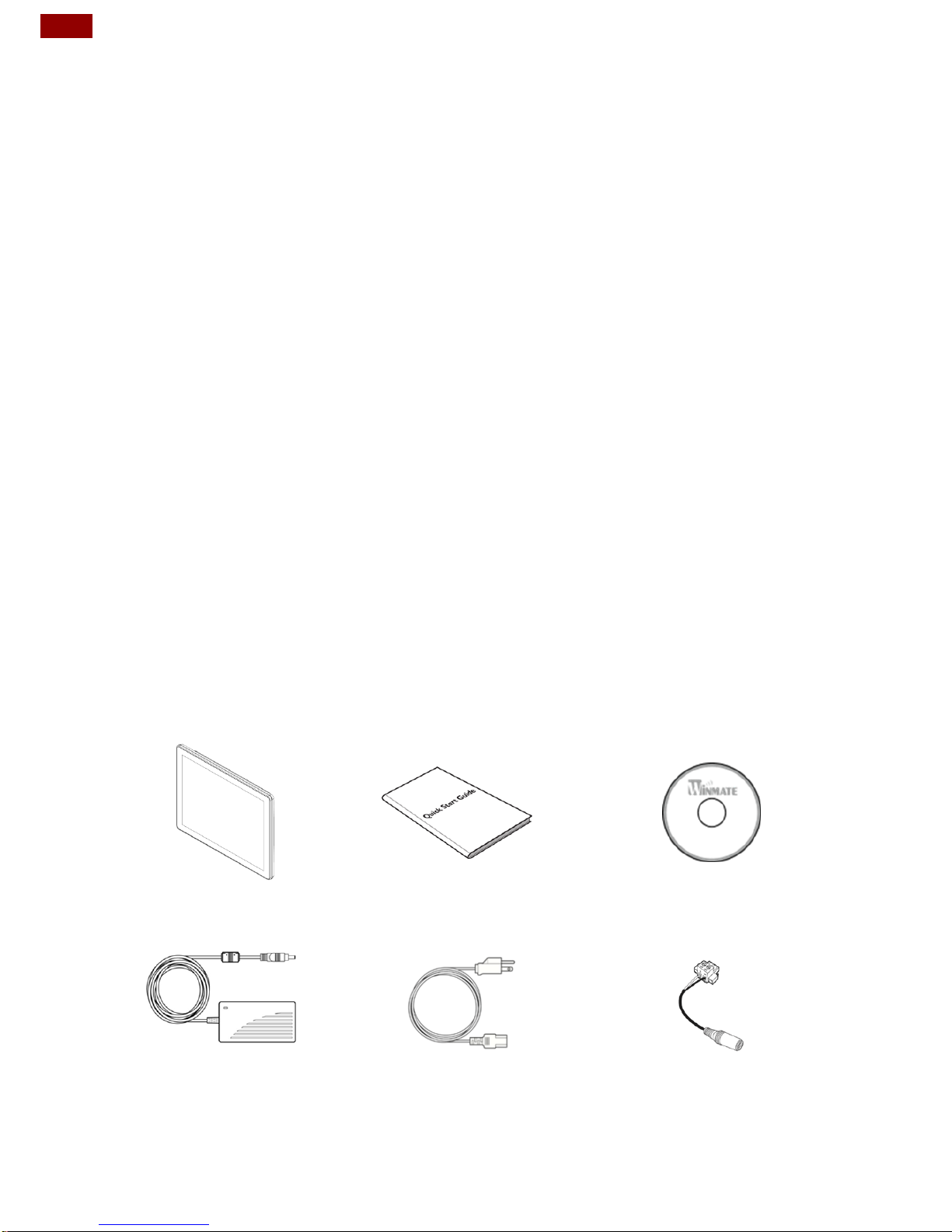
Carefully remove the box and unpack your device. Please check if all the items
listed below are inside your package. If any of these items are missing or
damaged contact us immediately.
Standard factory shipment list:
HMI Device
Quick Start Guide
Driver CD
Varies by product specifications
Part No. 91521110101W
Part No. 9171111I103L
AC Adapter 12V/ 50W
Power Cord
Terminal Block to DC
Jack
Part No.922D050W12VA
Varies by country
Part No. 94J602G020K0
Page 9
9
Chapter 1: Introduction
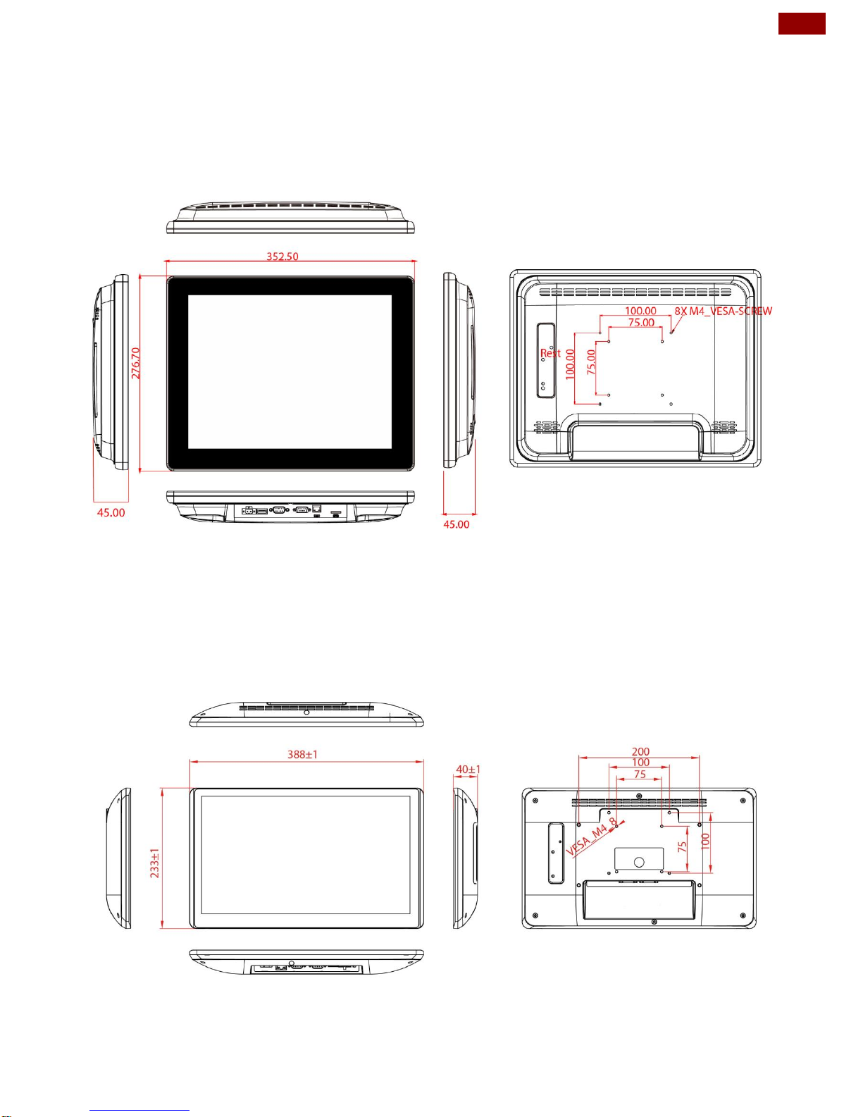
1.3 Mechanical Dimensions
15-inch, R15FA3S-PTC3
Unit: mm
Dimensions:352.50 x 276.70 x 45
15.6-inch, W15FA3S-PTA3
Unit: mm
Dimensions:388 x 233 x 40
Page 10
10
PT Series Android HMI User Guide
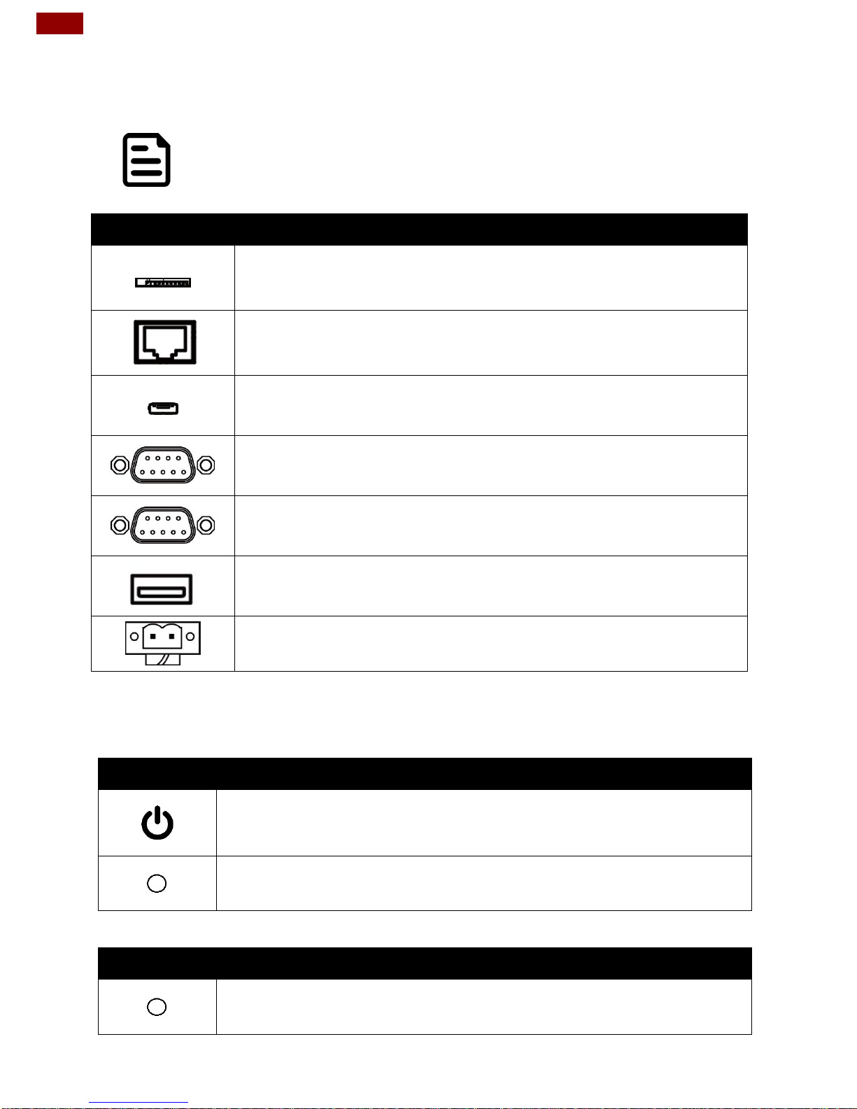
1.4 Connector Description
Terminal interfaces are located on the bottom side of the HMI device.
Note:
Notice that input and output connectors vary by product size and specifications.
Terminal interfaces description:
Item
Description
MicroSD Card Slot –Insert microSD card to expand the storage.
RJ45 – Connects HMI device to Ethernet network. Supports PoE for
power transmission in network equipment, via network UTP cable,
together with data.
USB OTG –. Connect to PC for client use and update OS Image.
RS-232/422/485 – Connects external devices to HMI device.
Example: A barcode reader or scanner to HMI device.
CANBus – Allow device to communicate with each other without host
computer.
Example: A machine controller to HMI device.
USB 2.0- Connects USB2.0 compatible devices to HMI device.
Example: A printer to HMI device.
2 Pin Terminal Block – Use to provide DC power to HMI device.
1.5 Physical Buttons and LED Indicators
PT Series HMI has Power and Reset physical buttons located on the back side.
Item
Description
Power Button – Press to turn on/ off the device.
Reset Button – Press to forcible shut down and reset the device.
PT Series HMI has Power LED indicator located on the back side.
Item
Description
Power LED Indicator – Lights up when HMI device is powered on.
Page 11

11
Chapter 2: Installation
Chapter 2: Installation
2.1 Wiring Requirements
The following common safety precautions should be observed before installing any
electronic device:
Strive to use separate, non-intersecting paths to route power and networking
wires. If power wiring and device wiring paths must cross make sure the wires
are perpendicular at the intersection point.
Keep the wires separated according to interface. The rule of thumb is that
wiring that shares similar electrical characteristics may be bundled together.
Do not bundle input wiring with output wiring. Keep them separate.
When necessary, it is strongly advised that you label wiring to all devices in
the system.
Caution
Do not run signal or communication wiring and power wiring in the same
conduit. To avoid interference, wires with different signal characteristics (i.e.,
different interfaces) should be routed separately.
Be sure to disconnect the power cord before installing and/or wiring your
device.
Verify the maximum possible current for each wire gauge, especially for the
power cords. Observe all electrical codes dictating the maximum current
allowable for each wire gauge.
If the current goes above the maximum ratings, the wiring could overheat,
causing serious damage to your equipment.
Be careful when handling the unit. When the unit is plugged in, the internal
components generate a lot of heat which may leave the outer casing too hot
to touch.
Page 12
12
PT Series Android HMI User Guide
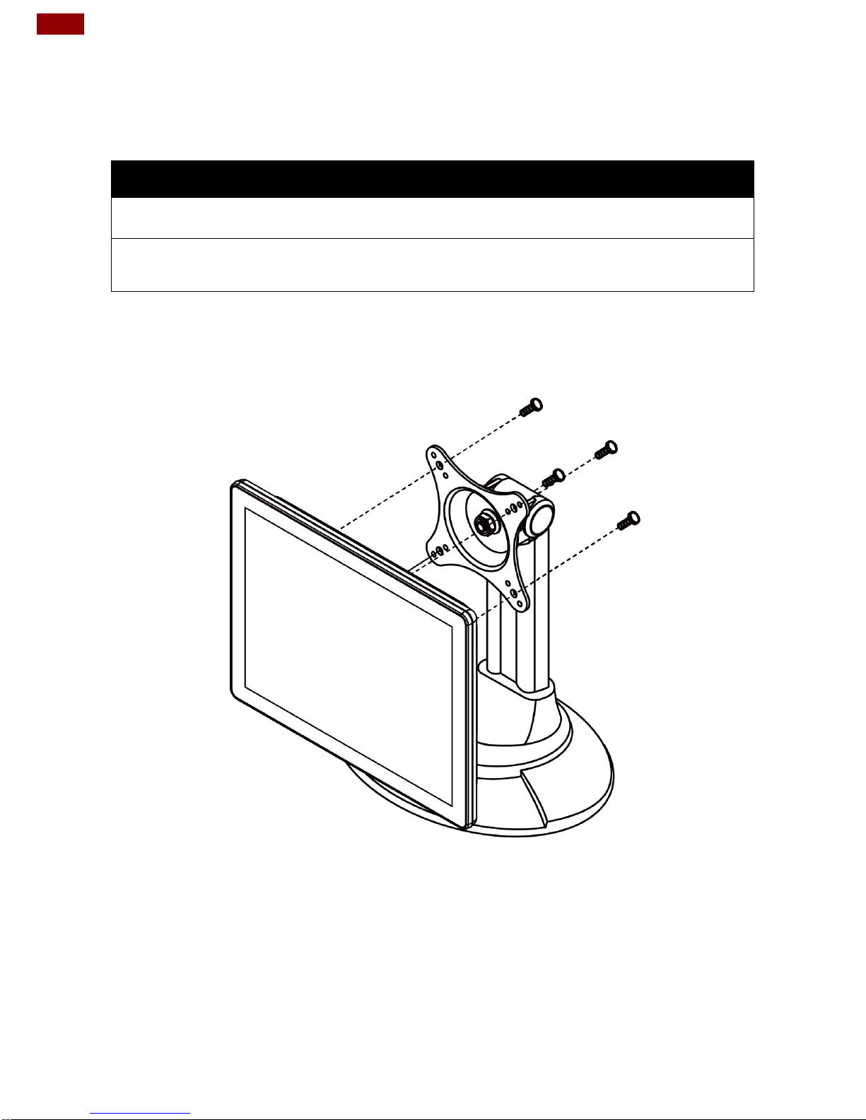
2.2 VESA Mounting
This device supports VESA Mounting and provides various types of mounting
options to fit any industrial use.
Size
VESA Plate
Screw Size
15”
75x75 mm, 100x100 mm
M4 x 5
15.6”
75x75 mm, 100x100 mm, 200 x 100 mm
M4 x 8
Mounting Instruction
Use Philips M4x5 screws to fix the desk stand to VESA holes on the back cover of
the device.
*The picture is for demonstration purposes only. VESA mount accessories are not
supplied by Winmate.
Page 13
13
Chapter 2: Installation
2.3 Turning On
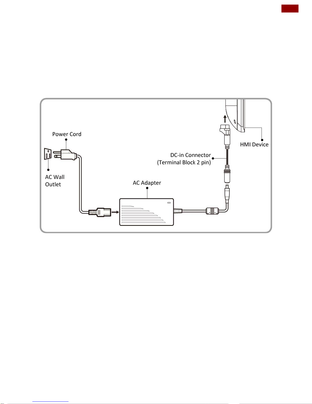
Follow the following steps to turn on your device:
1. Connect one side of 2-pin terminal block to DC jack connector to the HMI.
Connect the other side to the AC adapter.
2. Connect the power cord to AC adapter.
3. Plug the power cord to the AC outlet.
4. Press Power button on the rear OSD panel.
Page 14
14
PT Series Android HMI User Guide
2.4 Connecting Peripherals
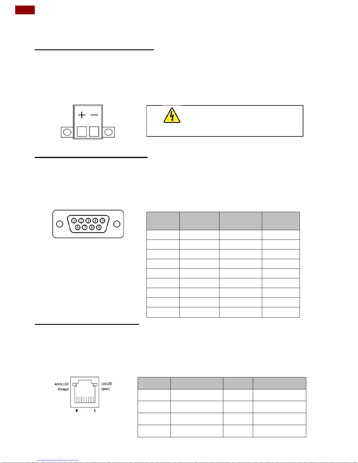
2.4.1 Power Input Connector
The DC power source input of the HMI is a 2 pin terminal block connector that
supports 12V DC power input.
Pin assignment and signal names of power input connector
2.4.2 Serial Port Connector
The HMI has one serial port connector to connect your device to external devices
such as mouse, modem or printer.
Pin assignment and signal names of serial port
You can configure serial port
settings by software.
2.4.3 Ethernet Connector
The HMI supports one RJ45 10/100/1000 Mbps Ethernet interface for connecting
to the internet.
Pin assignment and signal names of Ethernet connector
Voltage
Minimum Voltage 11.4V
Maximum Voltage 12.6V
Maximum Current 4.2A
Pin №
RS-232
(Default)
RS-422
RS-485
1
DCD
TxD-
D-
2
RXD
TxD+
D+
3
TXD
RxD+
NC
4
DTR
RxD-
NC
5
GND
GND
GND
6
DSR
NC
NC
7
RTS
NC
NC
8
CTS
NC
NC
9
RI
NC
NC
Pin №
Signal Name
Pin №
Signal Name
1
TX1+
2
TX1-
3
TX2+
4
TX2-
5
TX3+
6
TX3-
7
TX4+
8
TX4-
Page 15
15
Chapter 2: Installation
IMPORTANT:
Power Device (PD): follows IEEE 802.3at (25 Watt)
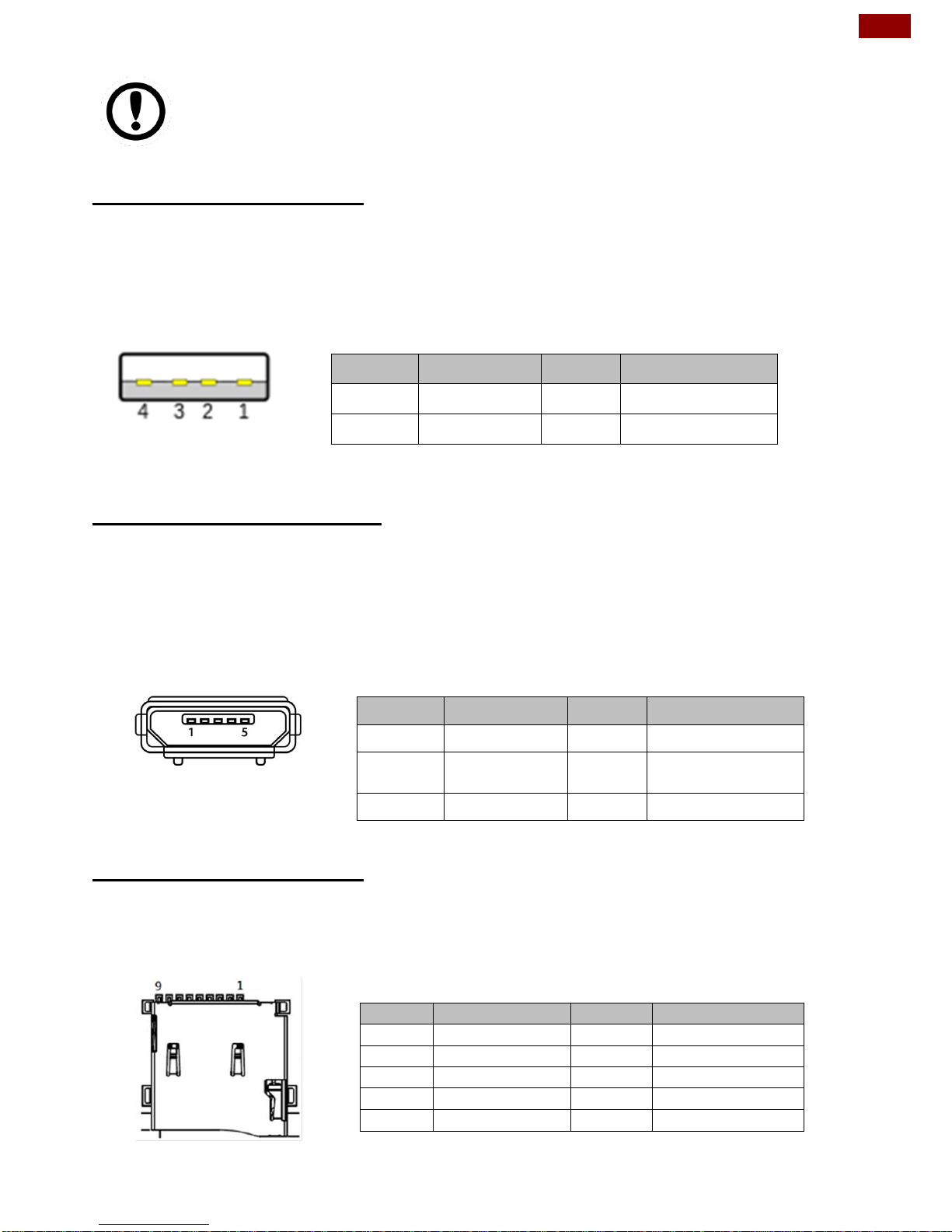
2.4.4 USB 2.0 Connector
Use USB A Type (USB 2.0) connector to connect your device to other USB 2.0
compatible devices.
Pin assignment and signal names of USB 2.0 connector
3.4.5 USB OTG Connector
Use USB OTG connector to connect the HMI to other USB On-The-Go compliant
devices such as flash drives, digital cameras, mice or keyboards. Use USB OTG
cable to install software on the HMI.
Pin assignment and signal names of USB OTG connector
3.4.6 Micro SD Card Slot
Insert microSD card to microSD card slot to extend the memory of your HMI.
Pin assignment and signal names of micro SD card slot
Pin №
Signal Name
Pin №
Signal Name
1
+5V
2
USB_D-
3
USB_D+
4
GND
Pin №
Signal Name
Pin №
Signal Name
1
+5V
2
USB_OTG_D-
3
USB_OTG_D
+
4
USB_OTG_ID
5
GND
Pin №
Signal Name
Pin №
Signal Name
1
DATA2
2
DATA3
3
CMD
4
+3.3V
5
CLK
6
GND
7
DATA0
8
DATA1
9
Card_Det
Page 16
16
PT Series Android HMI User Guide
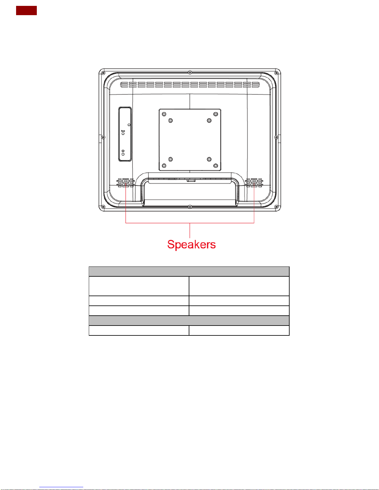
2.5 Speaker
Speaker is located on the rear side of the display.
Electrical Specifications
Rated impedance
6±15% ohms@2KHz,
1 Vrms input
Power Rating
0.67 W
Short Term Max Power
1.3W
Acoustical Specifications
Sound Pressure Level
75±3dB/40cm@1kHz
Page 17
17
Chapter 3: Operating the Device
Chapter 3: Operating the Device
The PT Series HMI runs on Android 6.0 operating system (Default).
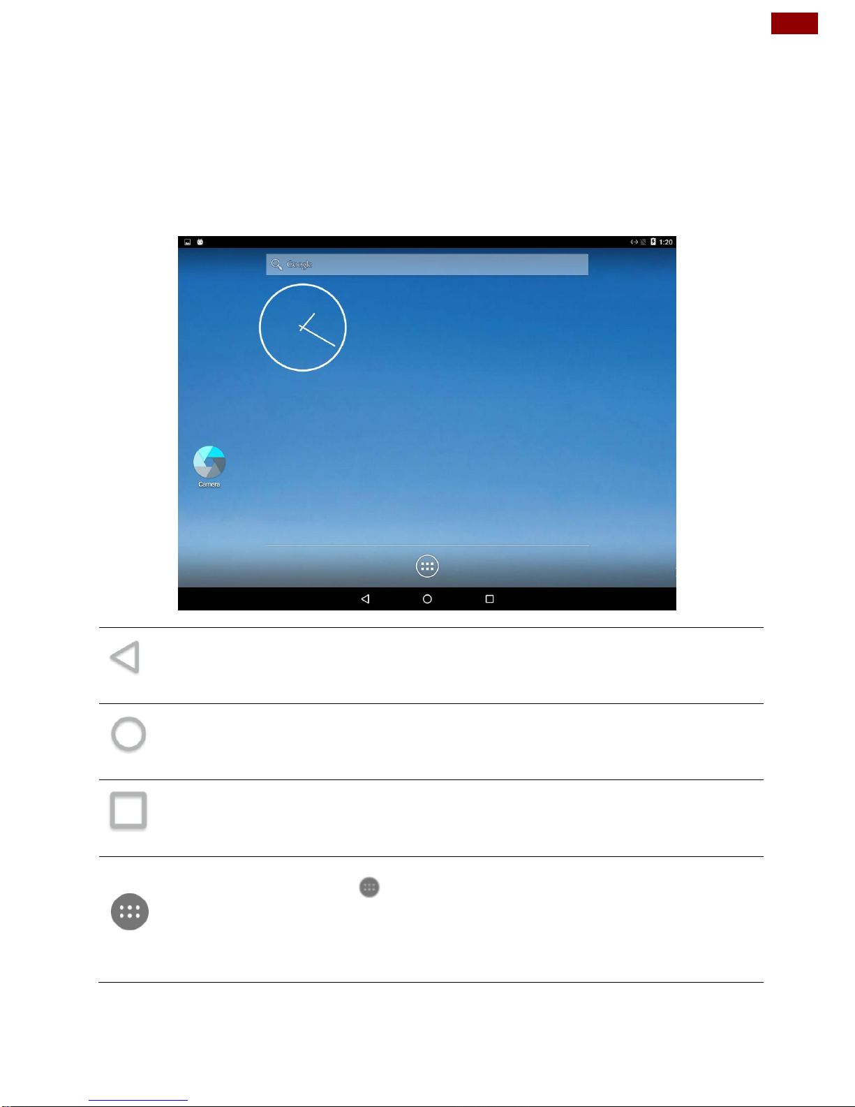
3.1 Home Screen
Your device runs on Android 6.0 operating system (Default).
Back
Opens the previous screen you were working in, even if it was in a different app.
Once you back up to the Home screen, you can’t go back any further.
Home
Returns to the Home screen. To get suggestions based on the screen you’re
currently viewing, touch & hold this button.
Overview
Opens a list of thumbnail images of screens you’ve worked with recently. To open
one, touch it. To remove a screen from the list, swipe it left or right or touch the X.
Your apps
To see all your apps, touch in the Favorites tray on any Home screen. This is
where you can see all your apps, including those that come with your phone or tablet
and those you downloaded on Google Play. You can move app icons to any of your
Home screens. The apps you’ve used most recently appear in the first row.
Page 18

18
PT Series Android HMI User Guide
Some apps hide these buttons temporarily, or fade them to small dots in the same
position. To bring them back, touch the dots, touch the screen in the middle, or
swipe up from the bottom.
Many screens in apps and Settings include a menu icon at the top right of the
screen. Touch it to explore additional options, including Help & feedback.
To add an app to a Home screen:
1. Go to the Home screen where you want to place the app.
2. Touch All Apps .
3. Swipe from left to right to find the app you want.
4. Touch & hold the app until the Home screen appears, slide it into place, and
lift your finger.
To remove an app icon from the Home screen without removing it permanently
from your device, touch & hold it, slide your finger toward the top of the screen, and
drop the app over Remove in the top left.
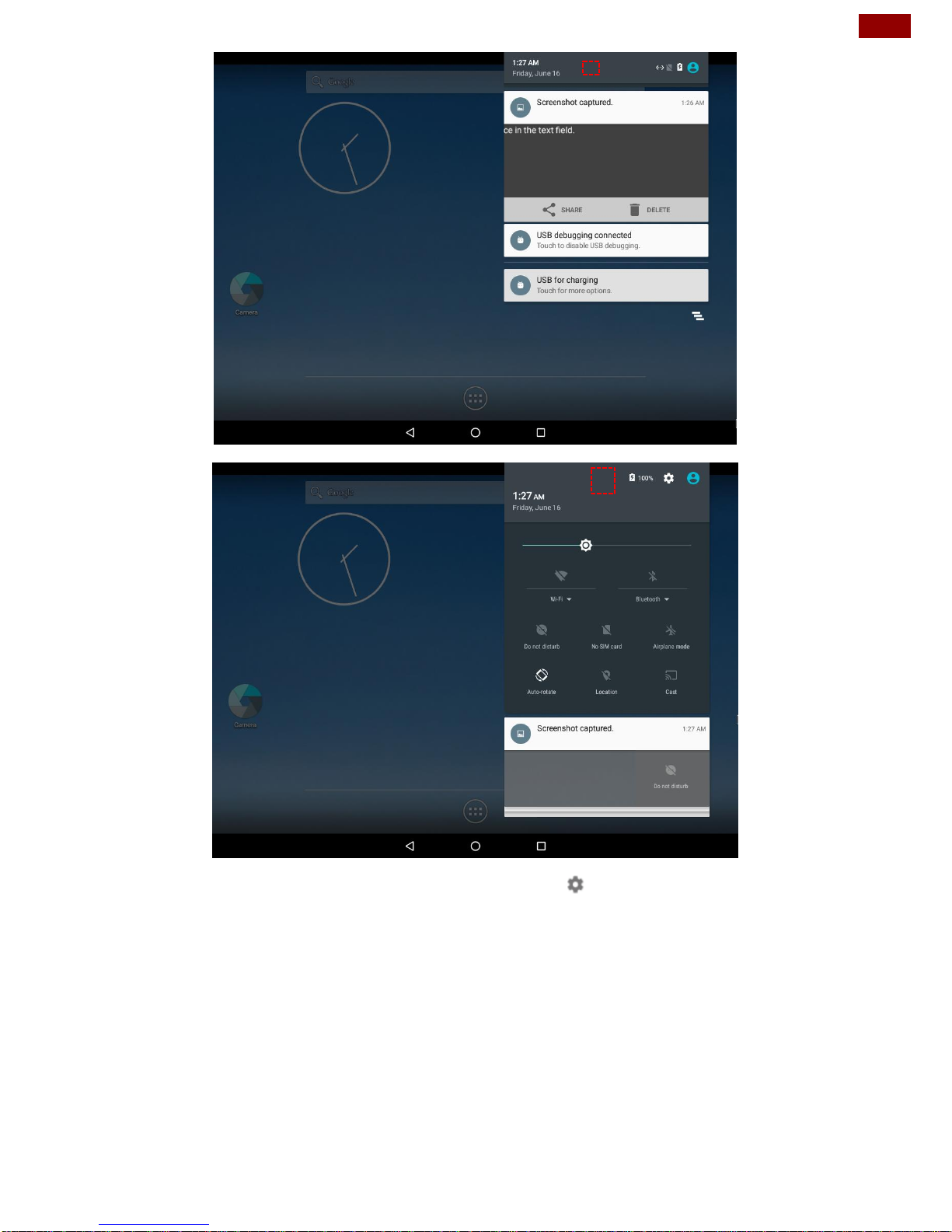
3.2 Quick Settings
You can open your device’s settings app from the All Apps screen or from Quick
Settings.
For example, to change notification sounds, and volume go to Settings > Device
> Sound to change the volume.
Use Quick Settings to easily change frequently used settings, like
turning on Wi-Fi. To open Quick Settings, swipe down from the top
of the screen with two fingers. To change a setting, just touch the
icon:
Display brightness: Slide to lower or increase the
brightness of your screen.
Wi-Fi network: Turn Wi-Fi on or off or open the Wi-Fi
settings menu.
Bluetooth settings: Turn Bluetooth on or off or open the
Bluetooth settings menu.
Auto-rotate: Lock your device’s orientation in portrait or
landscape mode.
Page 19
19
Chapter 3: Operating the Device
Open the main Settings menu by touching Settings at the top right.
Page 20
20
PT Series Android HMI User Guide
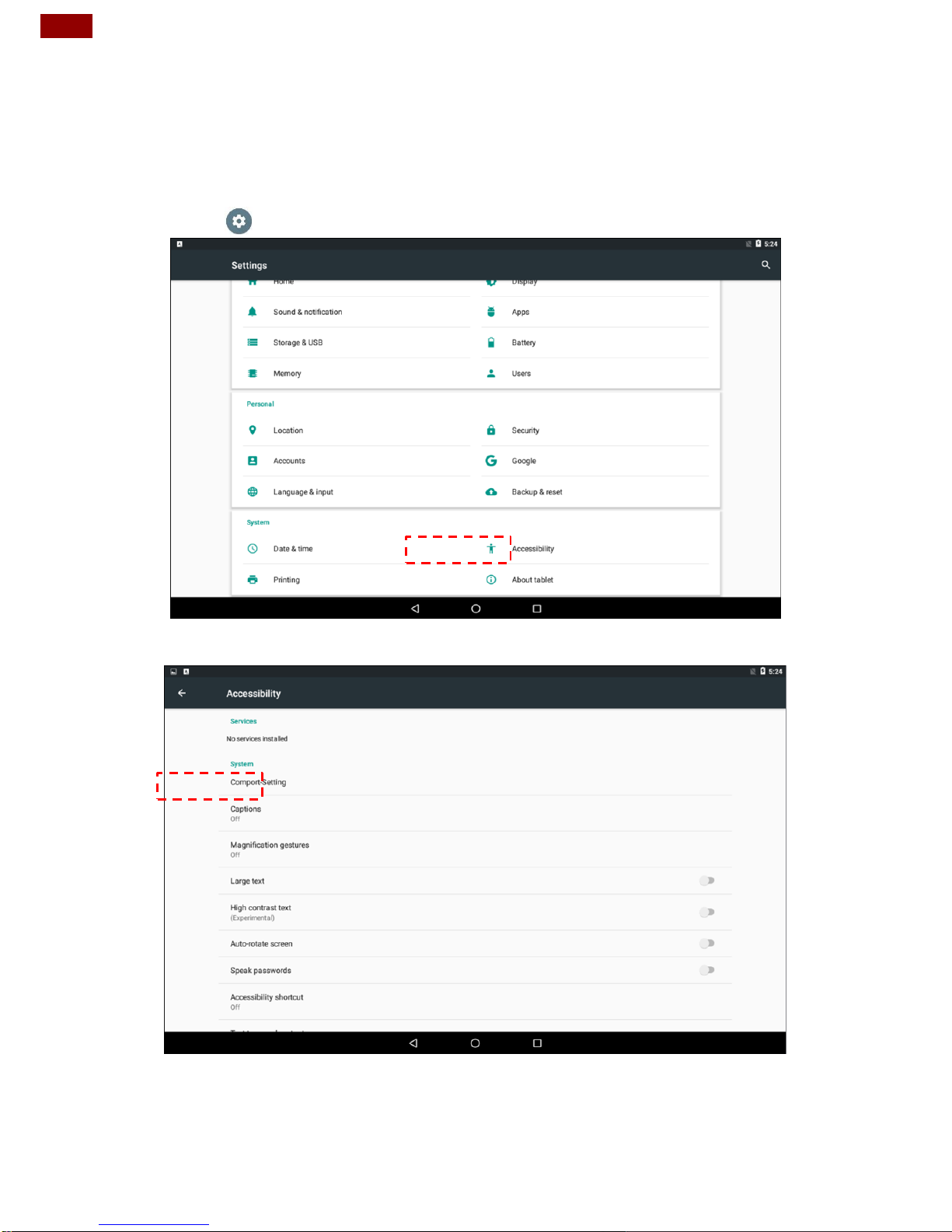
3.3 Configuring Serial Port Settings
Serial COM Port can be configured for RS-232, RS-422 or RS-485. Winmate
provide COM port settings application for Android OS.
To configure serial port settings:
1. Settings > Accessibility.
2. Accessibility > System: Comport-Setting.
Page 21
21
Chapter 3: Operating the Device
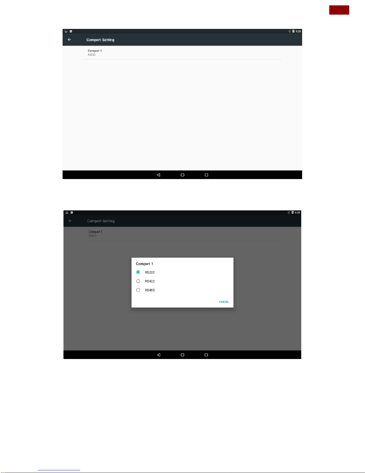
3. Comport-Setting > Comport 1/ Comport 2/ Comport 3
* Select Comport 1/ Comport 2/ Comport 3 that you want to configure.
4. Comport 1 > RS232/RS422/RS485
* Configure Comport 1 settings
Page 22
22
PT Series Android HMI User Guide
3.4 Brightness Adjustment
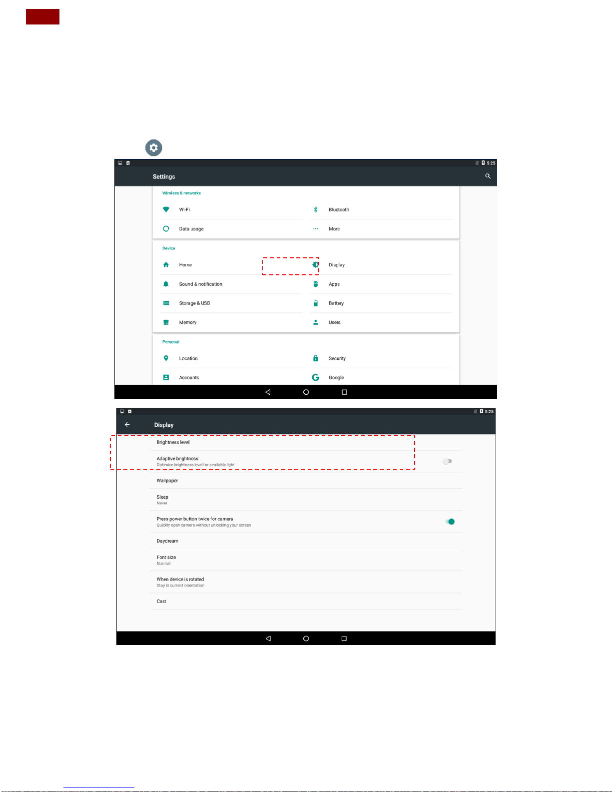
Use can adjust the screen brightness in Android settings. Pull down from the top of
the screen to get the notifications area. You can also access display settings in the
settings menu.
To adjust the brightness of the screen:
1. Settings > Display > Brightness Level
Tap the cursor to the left to reduce the screen brightness.
Tap the cursor to the right to increase the screen brightness.
Page 23
23
Chapter 3: Operating the Device
3.5 Ethernet
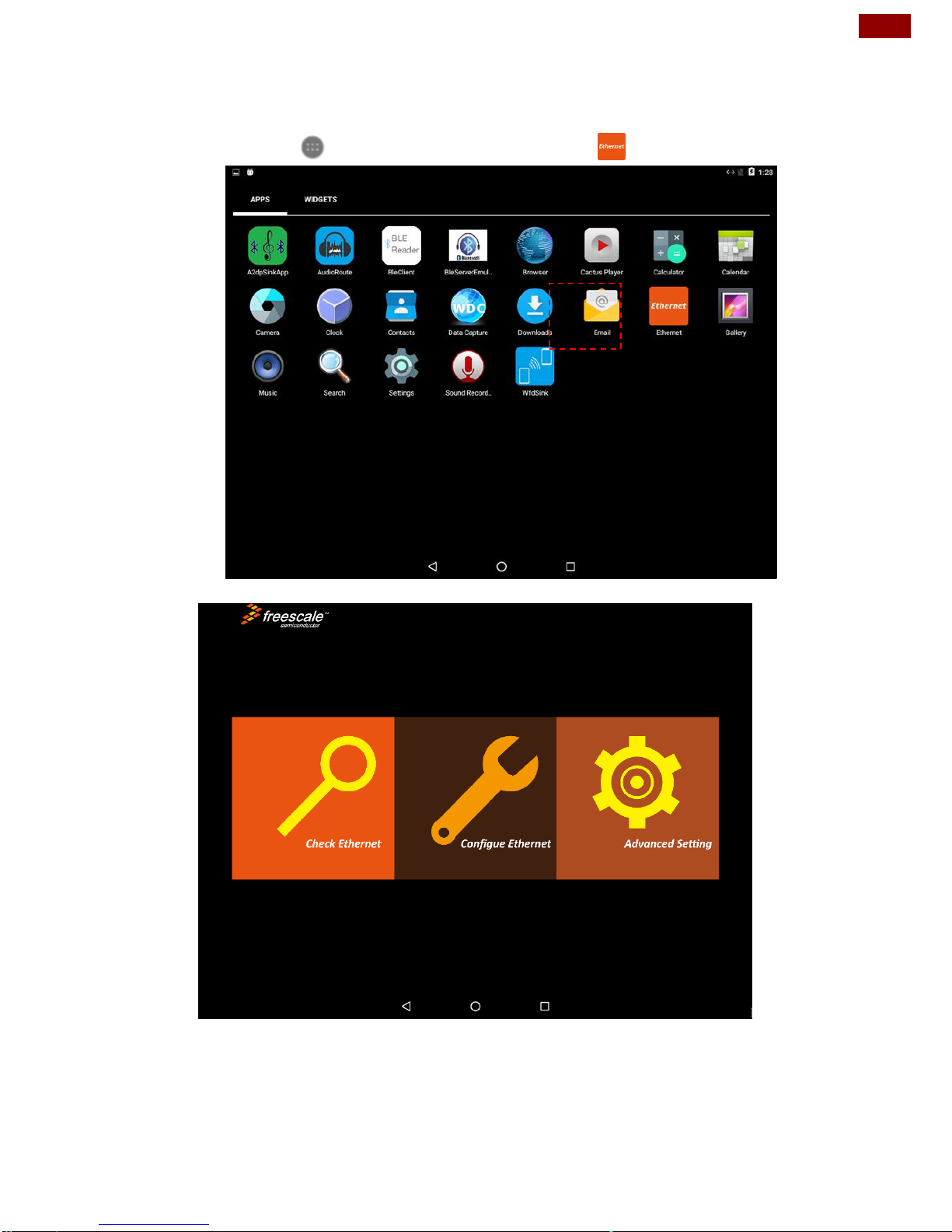
1. Connect Ethernet Cable to the HMI.
2. Touch All APPS icon, and the open Ethernet application.
3. Ethernet APP main menu appears
Page 24
24
PT Series Android HMI User Guide
3.5.1 Configuring Ethernet Settings
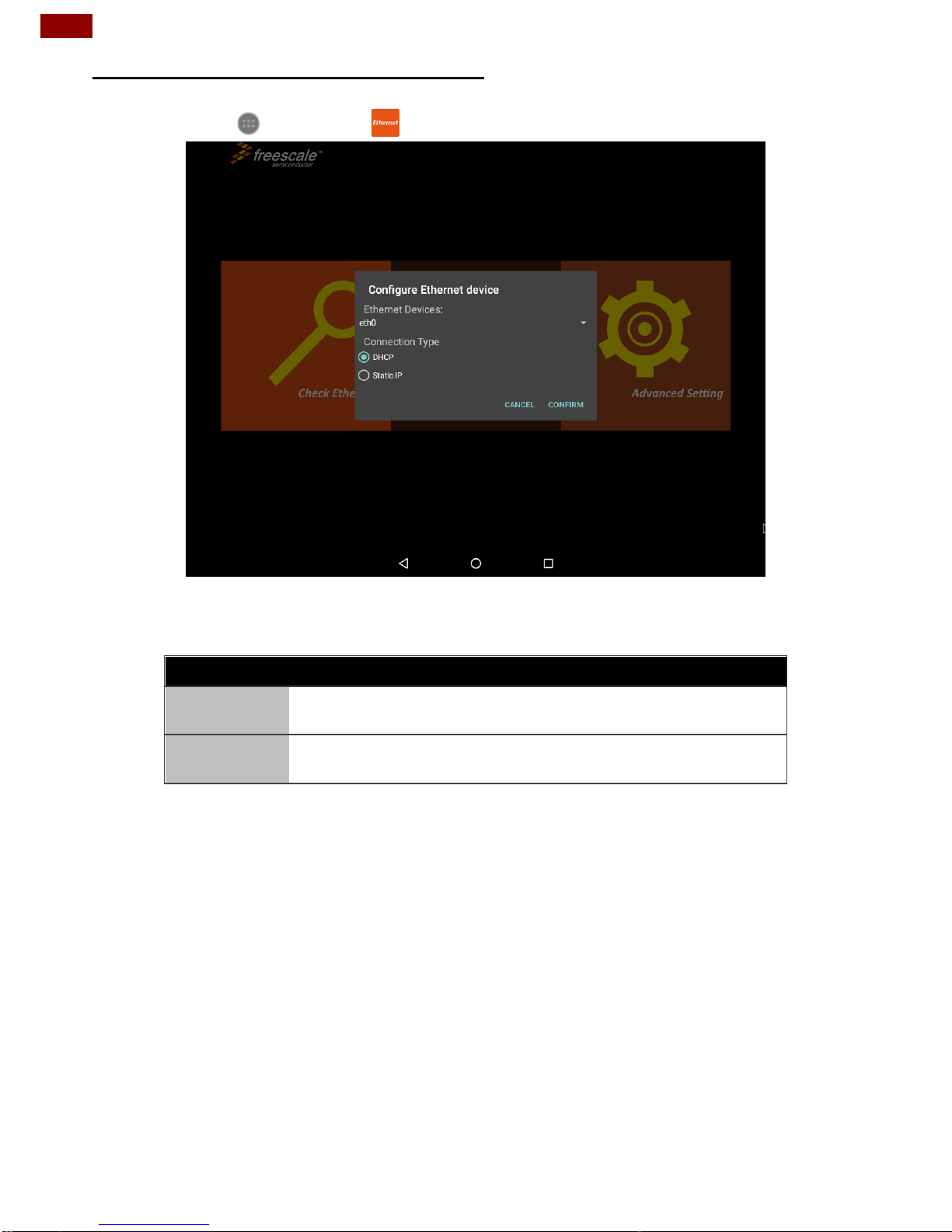
Go to All Apps > Ethernet > Configure Ethernet
*Ethernet OFF is set by default. Swipe Ethernet ON to activate Ethernet connection.
Connection Type
Setting
Description
DHCP
The device automatically capture IP-address from
the router
Static IP
Allows to manually set up IP-address, DNS, Network
and Gateway
Page 25
25
Chapter 3: Operating the Device
3.5.2 Configuring Ethernet
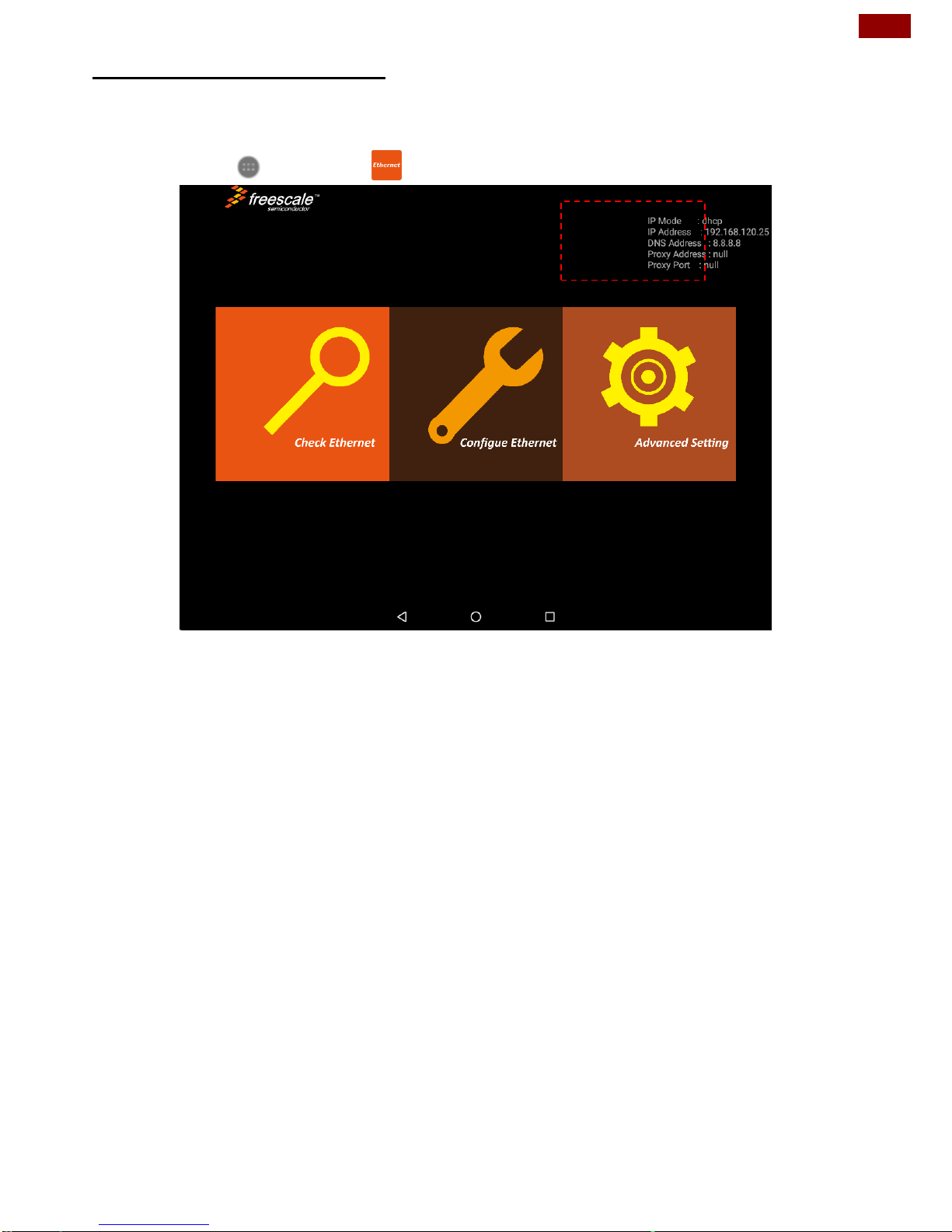
To check Ethernet settings:
Go to All Apps > Ethernet > Check Ethernet
Ethernet settings menu appears on the top right side of the desktop.
Page 26
26
PT Series Android HMI User Guide
3.6 Winmate® Home Manager (WHM)
Winmate® HMI running on Android OS comes with preinstalled APP named
Winmate® Home Manager (WHM) which let the device manager to lock the
launcher then the user can only use one application assigned by the device
manager.
3.6.1 How to Lock Applications
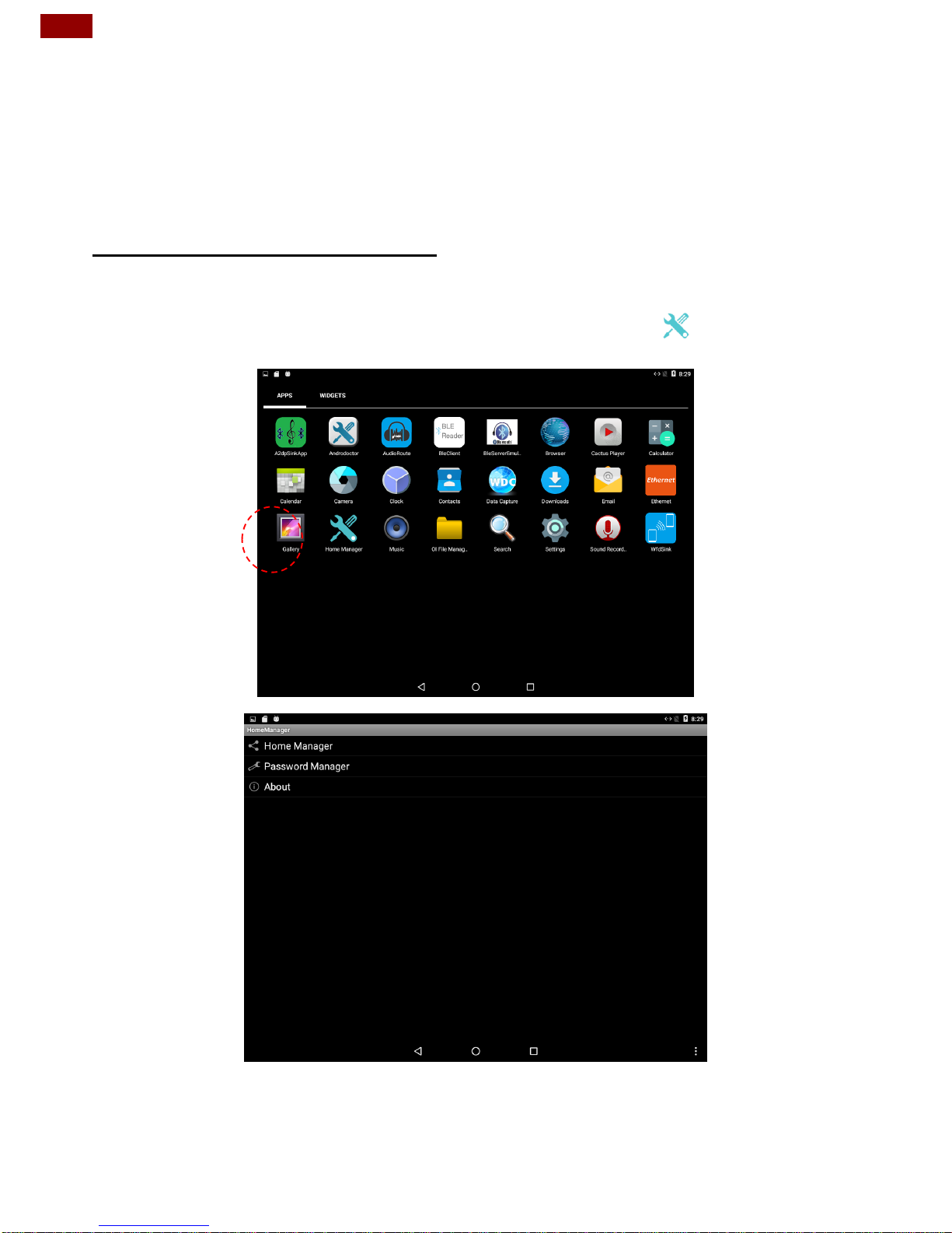
To lock applications:
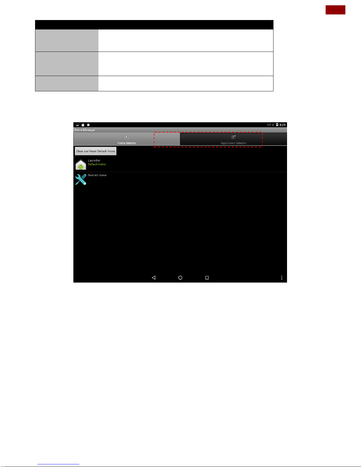
1. In the main APPS window, select the Home Manager APP and tap it to
open.
Page 27
27
Chapter 3: Operating the Device
Menu
Description
Home Manager
Set which app you want to run up automatically
after booting
Password
Manager
Set the WHM password (Default password is
“0000”).
About
Displays information about Home Manager
2. Go to “Application Selector”, and choose the app which you want to run up
automatically after booting.
Page 28
28
PT Series Android HMI User Guide
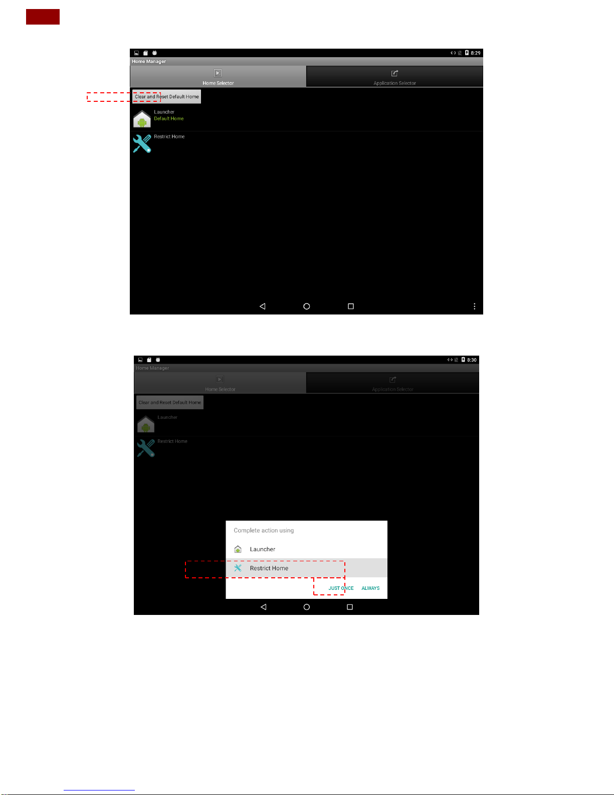
3. Go back to “Home Selector” and press “Clear and Reset Default Home”.
4. Select “Restrict Home” and “Always”, and then restart the computer to enable
these settings.
The system will automatically start the application which you selected and lock it.
Any time user presses home key or back key; the system will go back to the same
application which you have selected.
Page 29
29
Chapter 3: Operating the Device
3.6.2 How to Unlock Applications
Follow the instruction below to reset Home Manager.
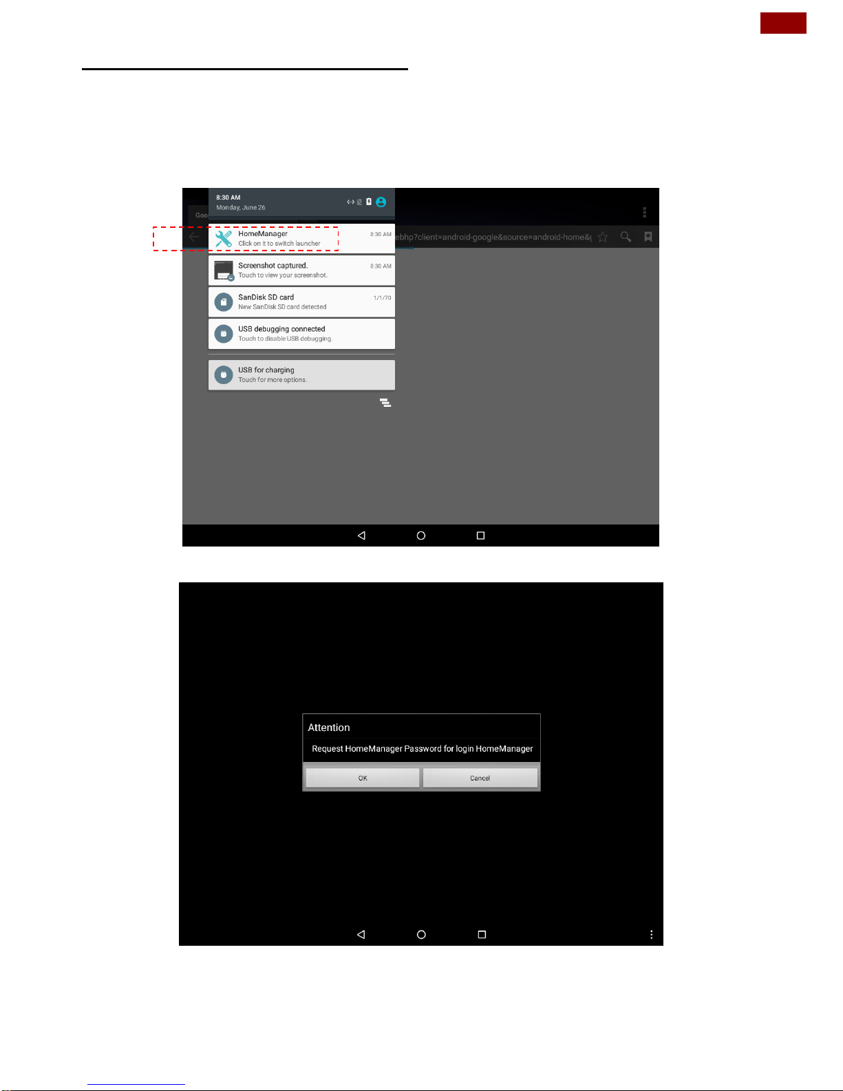
1. If you want to reset the home manager, pull down the left side to open the status
bar and open HomeManager.
2. System will request the password to login. Touch OK.
Default password is “0000”.
Page 30
30
PT Series Android HMI User Guide
3. Restart the system and you will go back to the normal Launcher.
3.6.3 How to Change Password
To change the password:
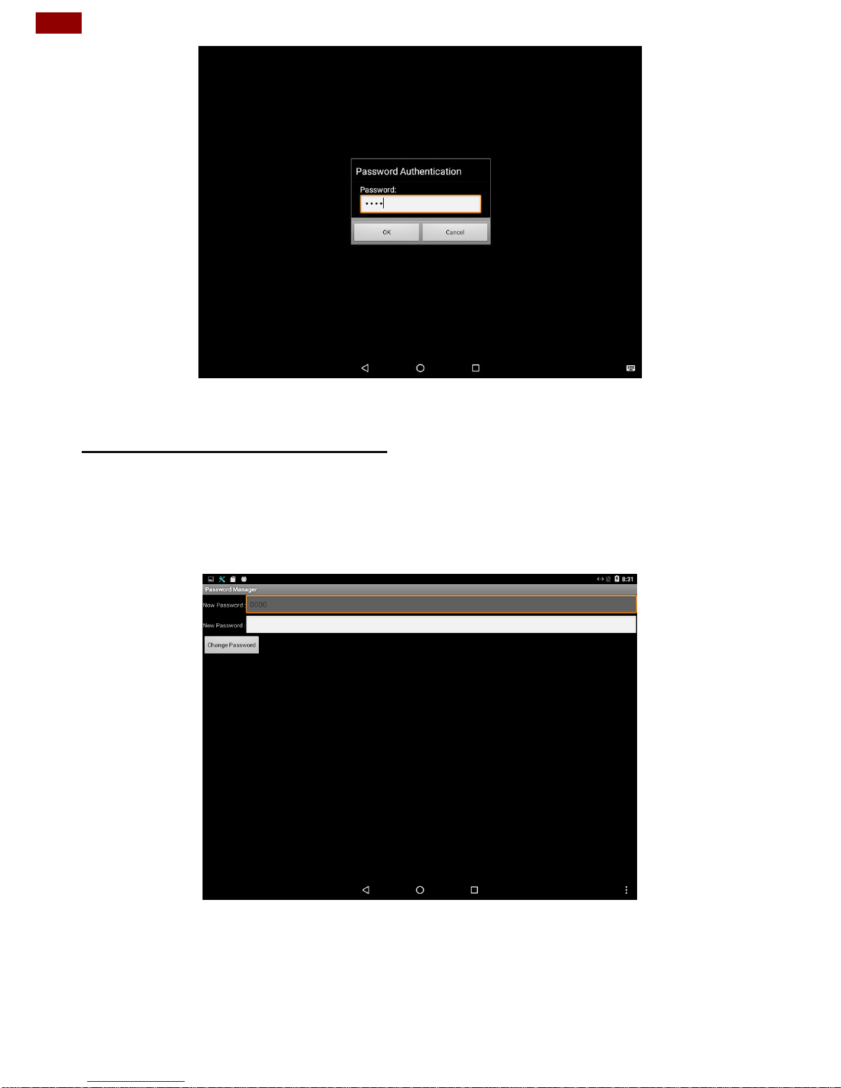
1. Go to Password Manager and set your own password for this APP.
2. The default password is “0000”. Enter a new password in New Password field,
and then tap Change Password.
Page 31
31
Chapter 4: Software Installation
Chapter 4: Software Installation
This chapter contains software installation and updates guide. All the programming
guides can be found in the driver CD included in the package.
4.1 Android Debug Bridge Driver Installation
You can find FA30-210 USB OTG driver in the CD that comes in the package:
CDM v2.08.28 Certified\ftdibus.inf
CDM v2.08.28 Certified\ftdiport.inf
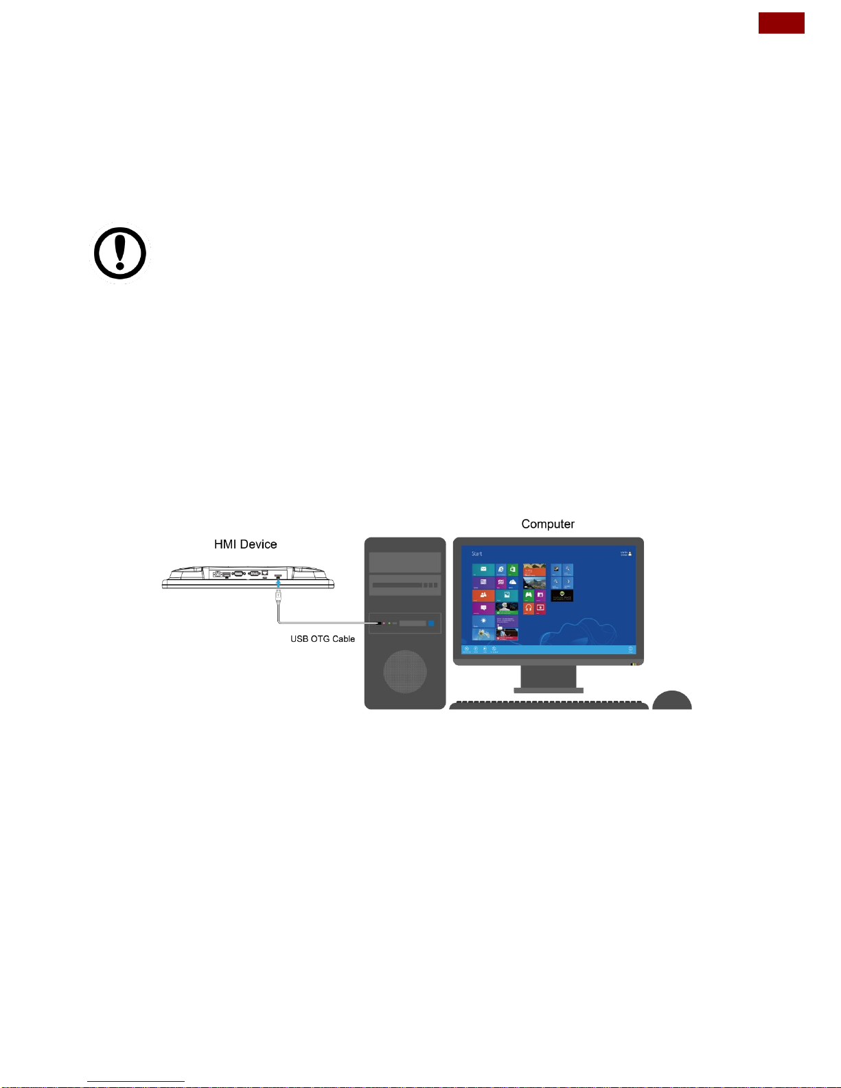
You need to connect HMI to the computer with the USB OTG cable. When using a
USB cable (not supplied with your device), verify that the cable or cable packaging
bears the “Certified USB™” mark (see below) to guarantee USB OTG compliance.
*I/O layout of the HMI device on the picture is for demonstration purposes only. Your
I/O layout may vary from the picture above.
IMPORTANT:
If your computer is running on Windows Embedded 8 Standard or
Windows 8.1 Industry Pro OS system, you need to disable driver
signature.
For Win XP / Win 7 skip disabling driver signature section, and
directly proceed to ADB driver installation.
Page 32
32
PT Series Android HMI User Guide
4.1.1 Disabling Driver Signature on Windows 8
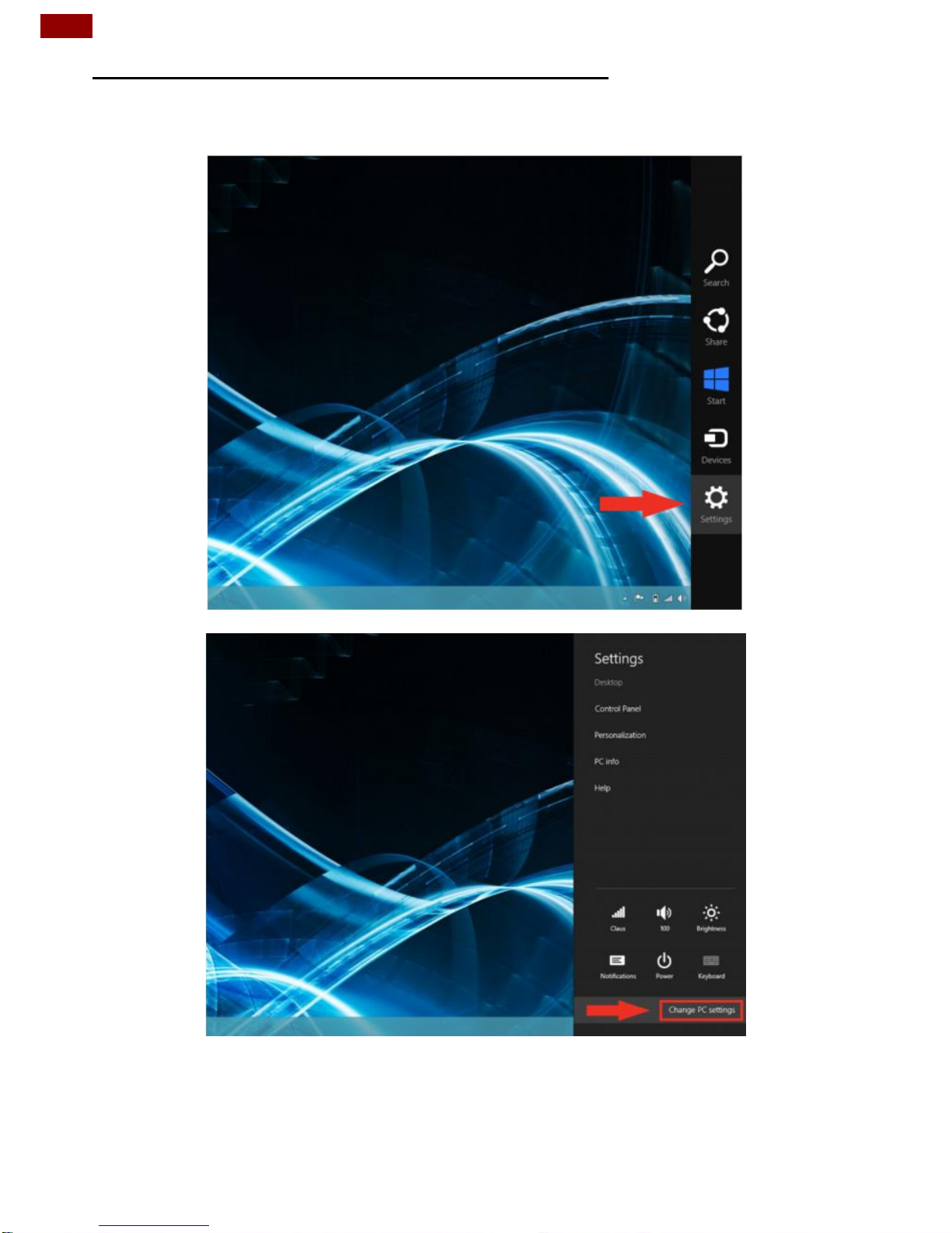
1. Hold down the Windows key on your keyboard and press the letter C to open
the Charm menu, and then click the gear icon (Settings).
2. Click Change PC Settings.
Page 33
33
Chapter 4: Software Installation
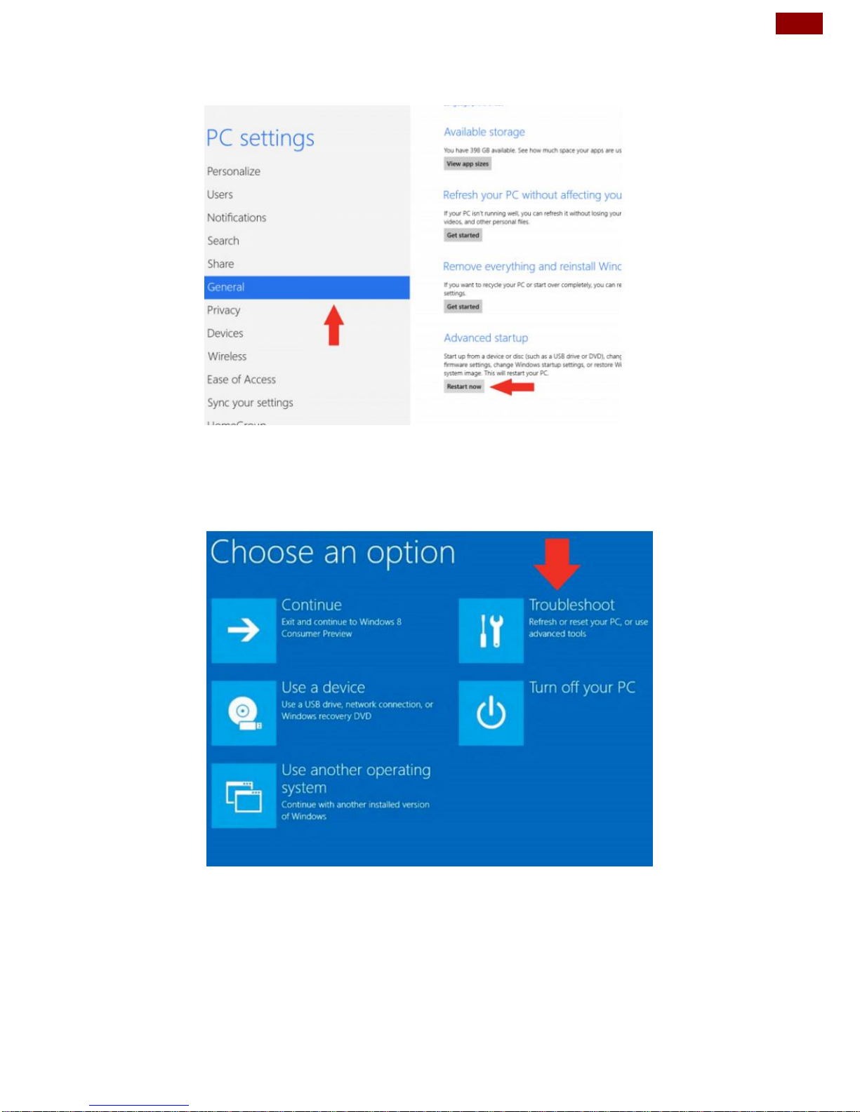
3. Click General.
4. Under Advanced Startup, click Restart Now.
NOTE: In Windows 8.1, the ‘Restart Now’ button has moved to ‘PC Setting ->
Update & Recovery -> Recovery.’
5. After restarting, click Troubleshoot.
Page 34
34
PT Series Android HMI User Guide
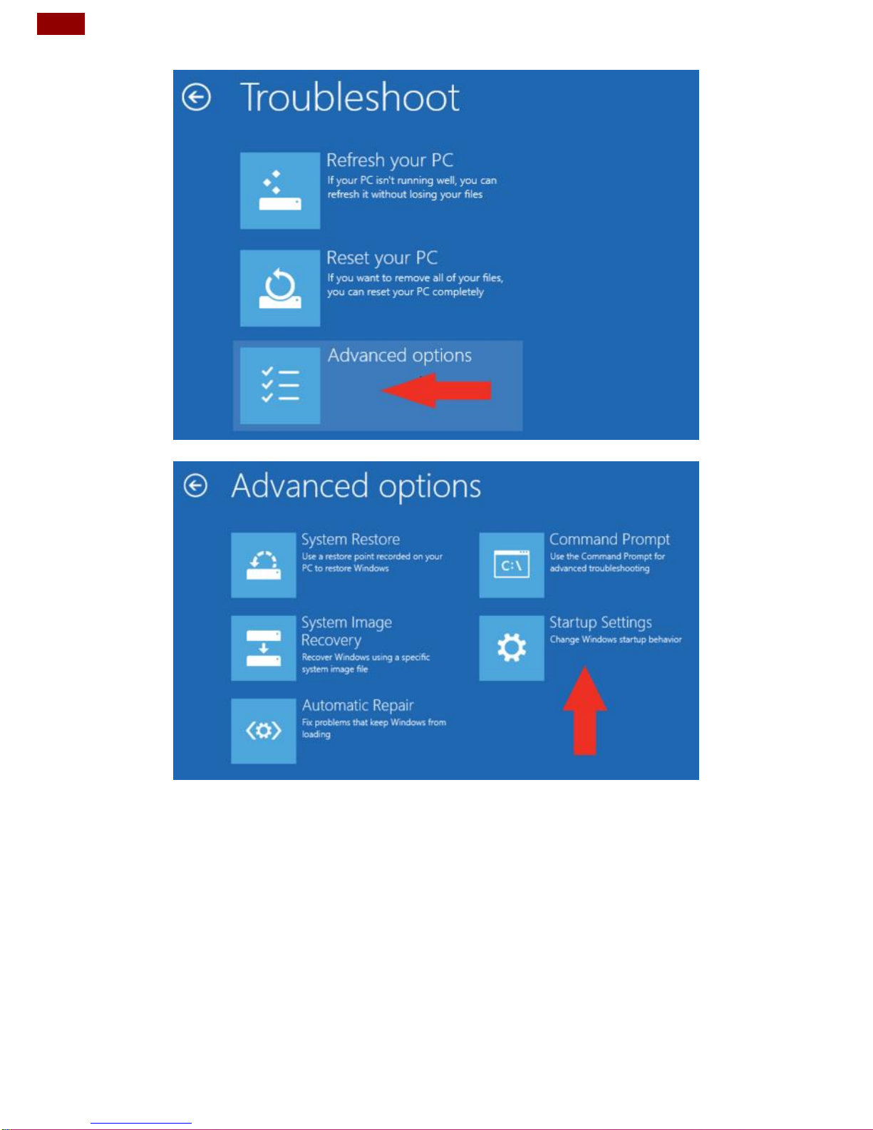
6. Click Advanced Options.
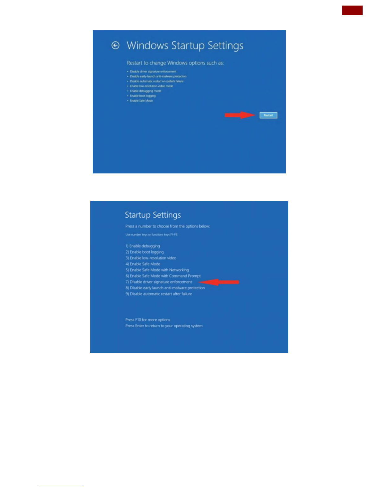
7. Click Windows Startup Settings.
Page 35
35
Chapter 4: Software Installation
8. Click Restart.
9. After restarting your computer a second time, choose Disable driver
signature enforcement from the list by typing the number 7 on your keyboard.
Your computer will restart automatically.
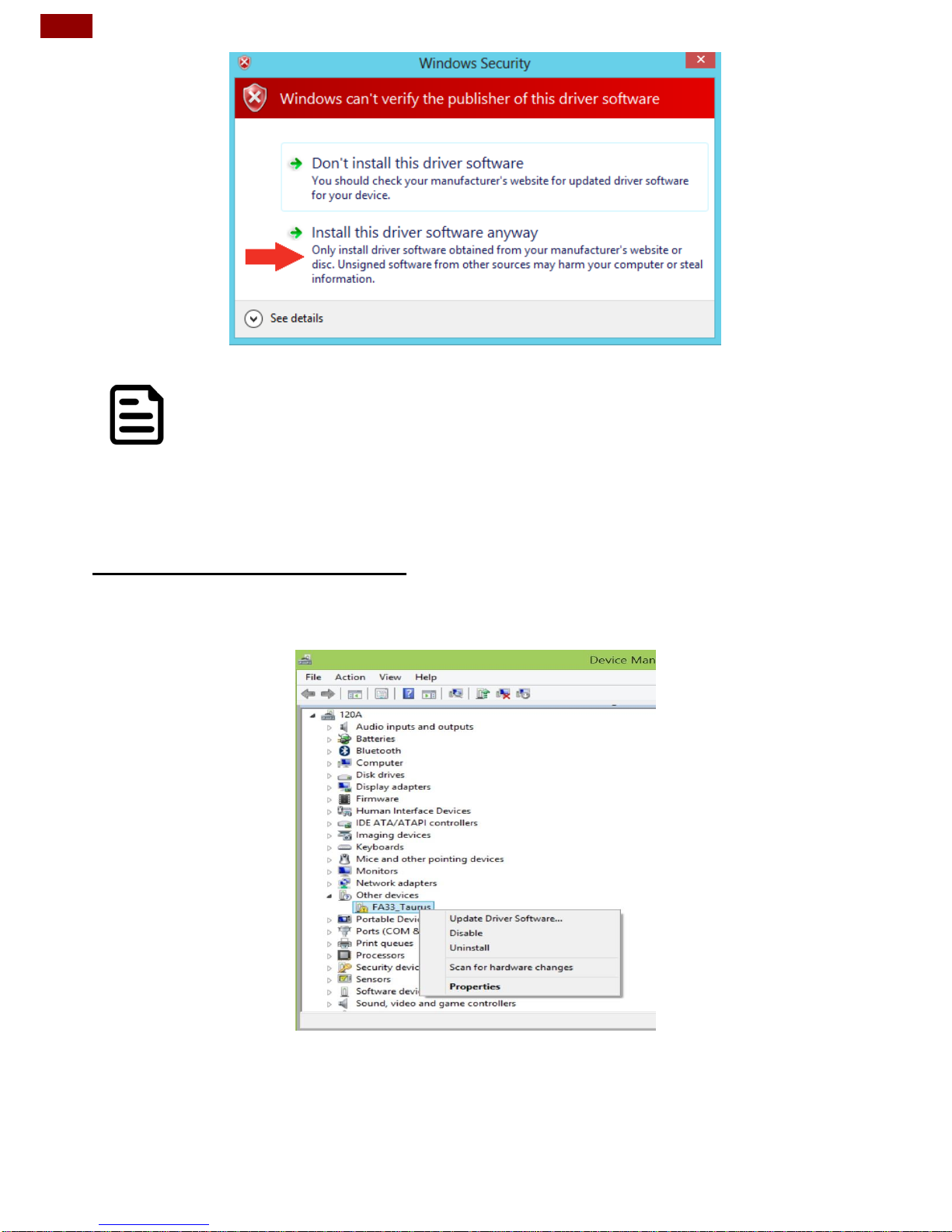
10. After restarting, you will be able to install the ADB drivers normally;
however, Windows will display a warning message. When the warning
appears, click Install this driver software anyway. If you are unfamiliar with
installing drivers, check out our Installing ADB driver tutorial for a step by step
guide.
Page 36
36
PT Series Android HMI User Guide
Note:
The next time you restart your computer, driver signature
enforcement will be in effect again. You will have to repeat this
process for any new boards. If you have multiple boards to use with
the same computer, we recommend installing the drivers for each
one before you shut down or restart your computer.
4.1.2 ADB Driver Installation
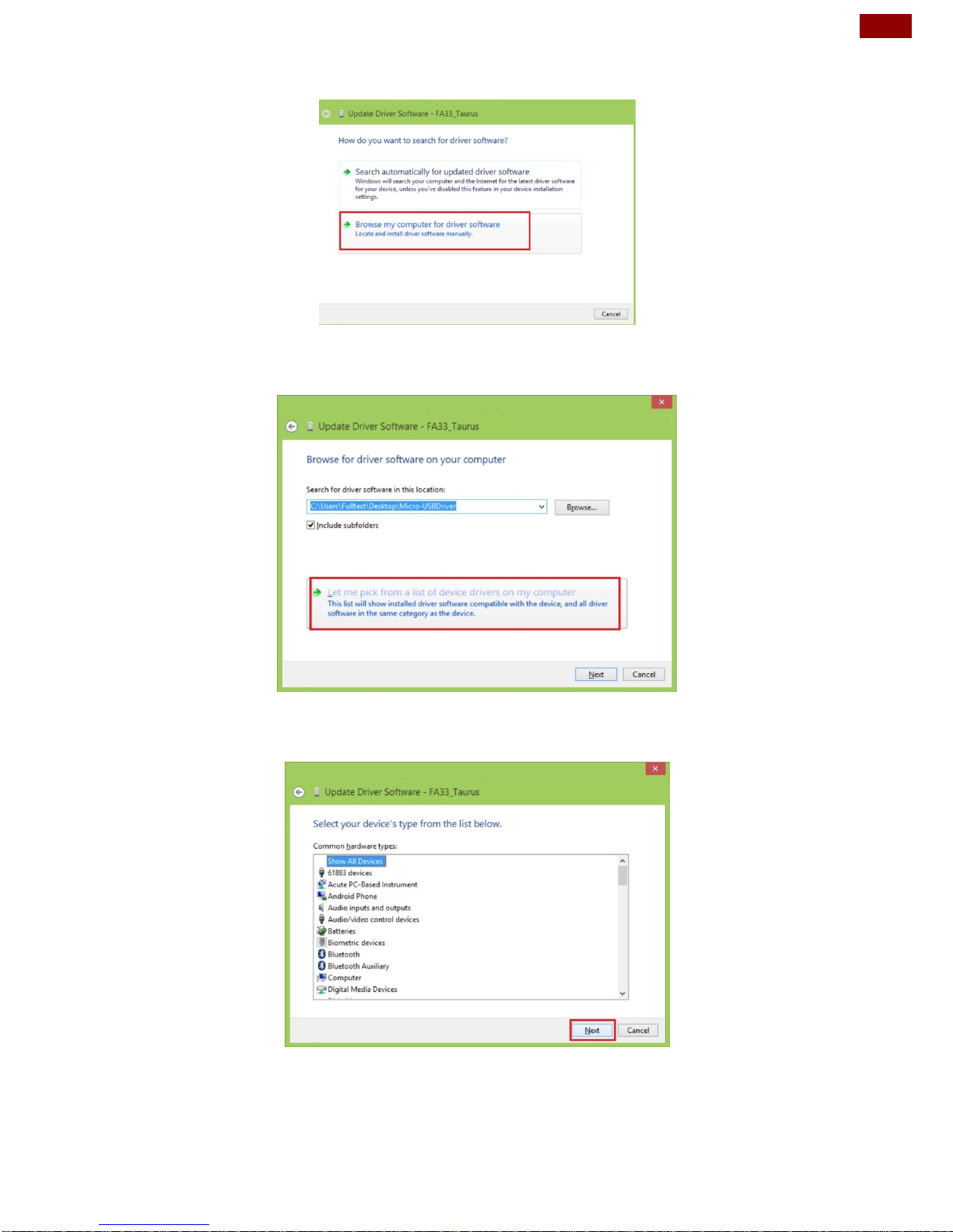
1. Confirm whether the USB device was found by the system. Device Manager >
120A > Other devices > FA34 > Update Driver Software
Page 37
37
Chapter 4: Software Installation
2. In the Update Driver Software window choose Browse my computer for
driver software.
3. Select Let me pick from a list of device drivers on my computer. Click
Next.
4. Select from your computer
5. In the Update driver software window, click show All Devices and then click
Next.
Page 38
38
PT Series Android HMI User Guide
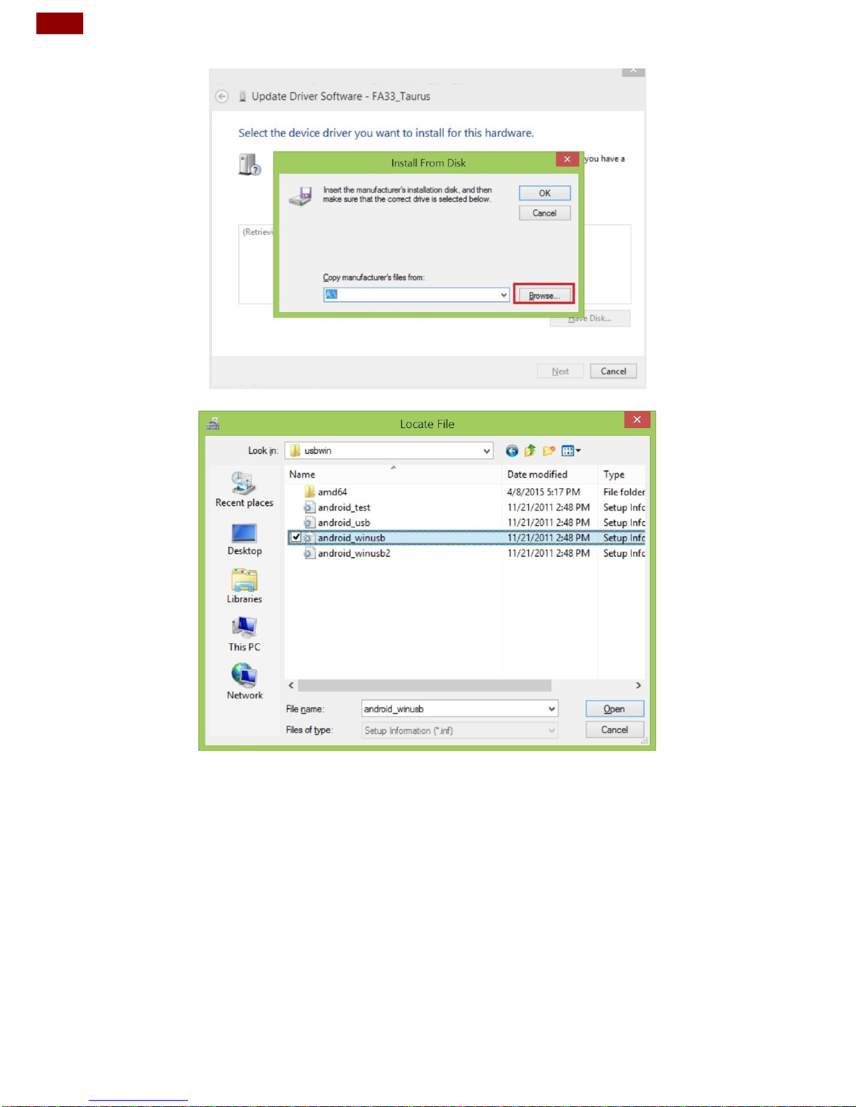
6. The system is looking for the driver folder. Click Browse.
7. Select the driver for your OS system. Click Open.
Page 39
39
Chapter 4: Software Installation
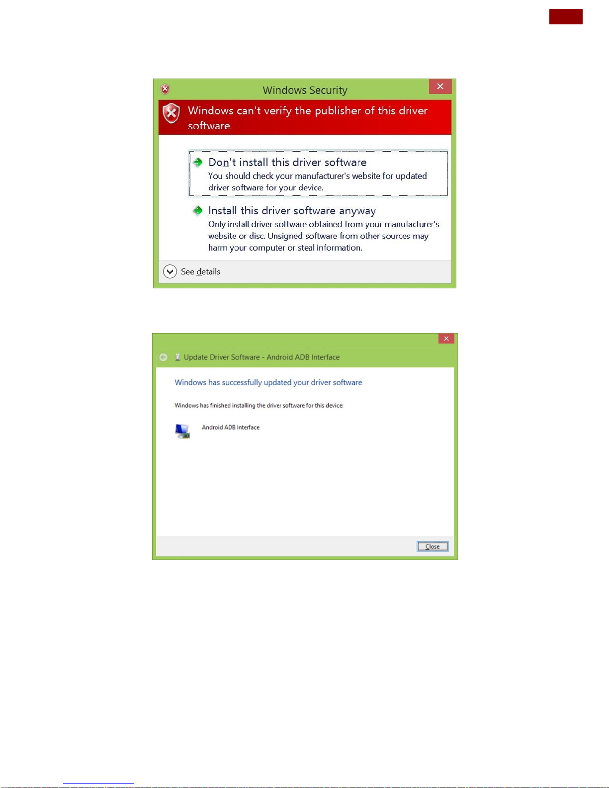
8. Windows Security window will pop up. This message is used to confirm
whether the user wants to install the driver. Select Install this driver software
anyway to continue.
9. When the installation is successfully completed you will see Android ADB
Interface driver in the Update Driver Software window. Now adb debug can
be carried out.
Page 40
40
PT Series Android HMI User Guide
4.2 Installing Android Debug Bridge (ADB)
For detailed Android Debug Bridge (ADB) information refer to Android Developers
Platform: http://developer.android.com/tools/help/adb.html .
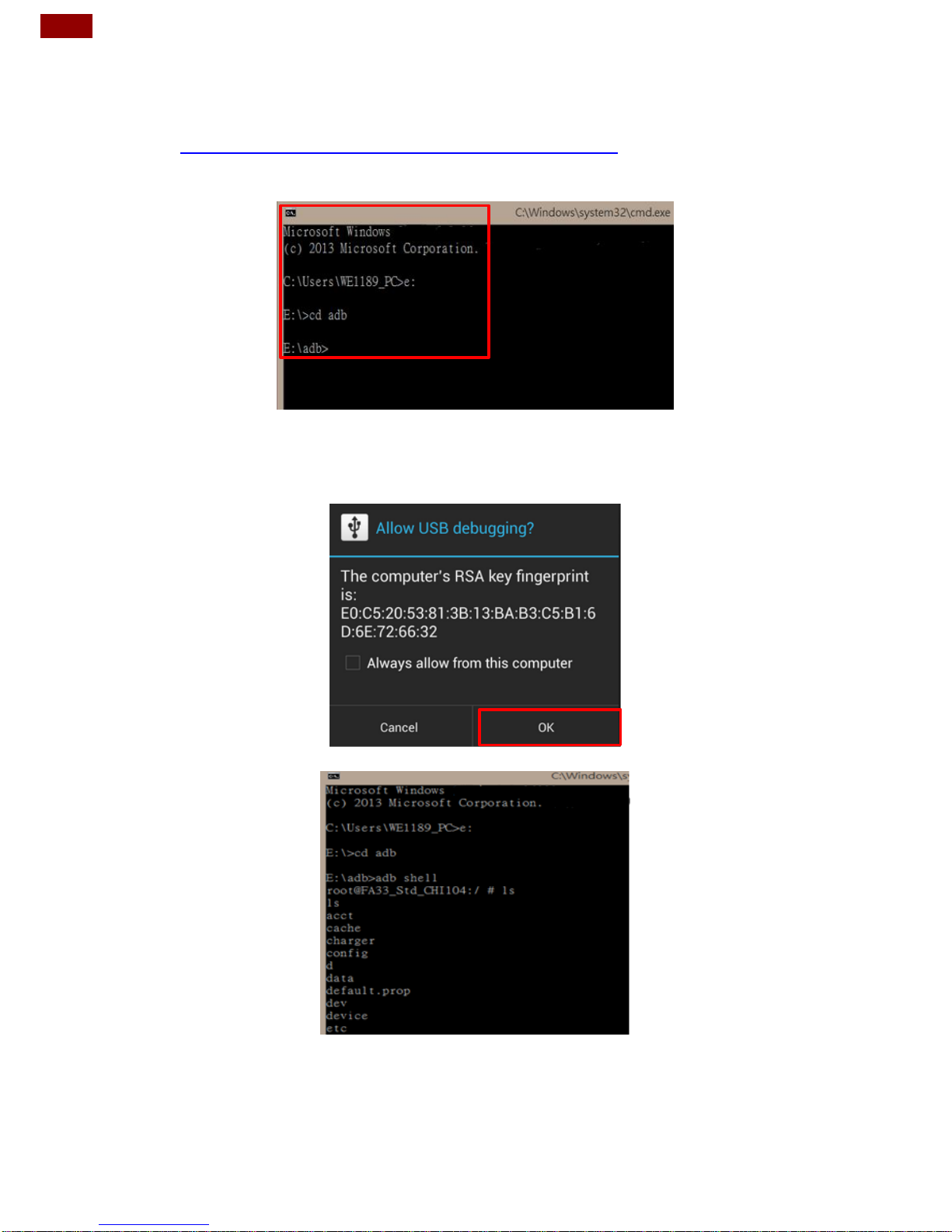
1. Decompress adb.zip. Open ADB terminal and move into the adb archive.
ADB Terminal window
2. Connect FA34 motherboard to the computer via USB. FA34 will ask you to
confirm USB debugging. Tap OK.
After ADB connection established, install APP or check system log via adb.
Page 41
41
Chapter 4: Software Installation
4.3 Downloading Image Tool
Download OS Image Tool update guide from Winmate Download Center:
4.4 OTA Update Guide
OTA is a tool which can help you to update OS image. To receive Android OS
image file contact our sales representatives. Once you get the image file follow the
guideline below.
To update OTA firmware:
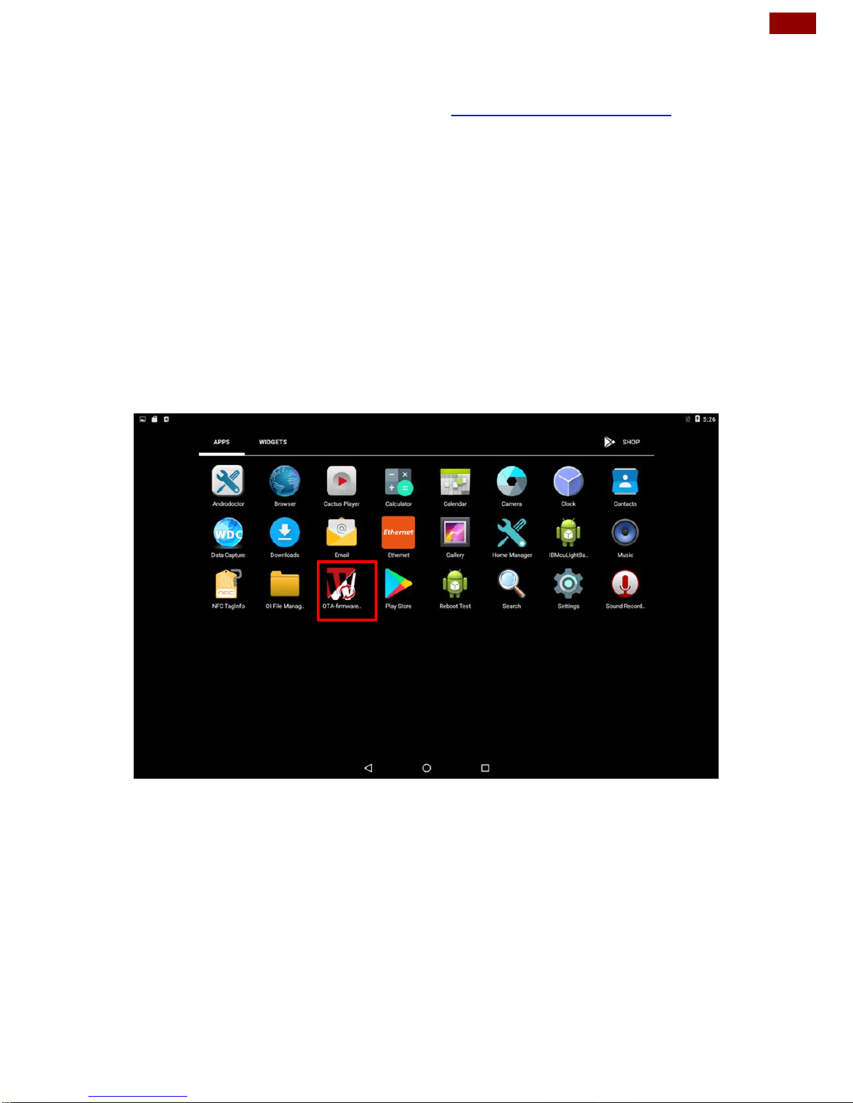
1. Copy image files ota_FA34_X_X_X_X.zip and FA34_X_X_X_X. md5 and to
micro SD card.
2. Insert micro SD card to the slot in the computer. In the APPs menu tap OTA
Image Upd.
Page 42
42
PT Series Android HMI User Guide
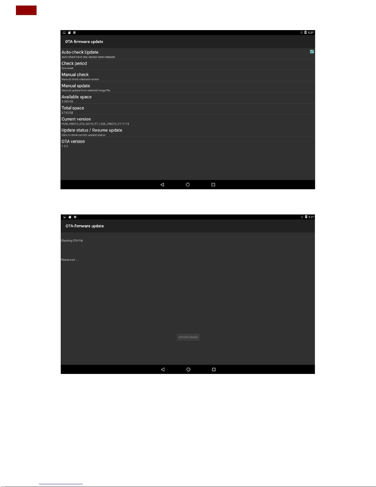
System shows OTA firmware related information.
3. Click Auto-check Update. The system is checking OTA File. It may take some
time.
Page 43
43
Chapter 4: Software Installation
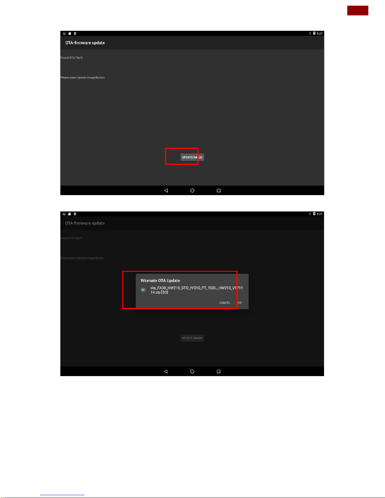
4. Tap Update Image
5. Make sure the file founded by the system is image update file. Tap OK.
Page 44
44
PT Series Android HMI User Guide
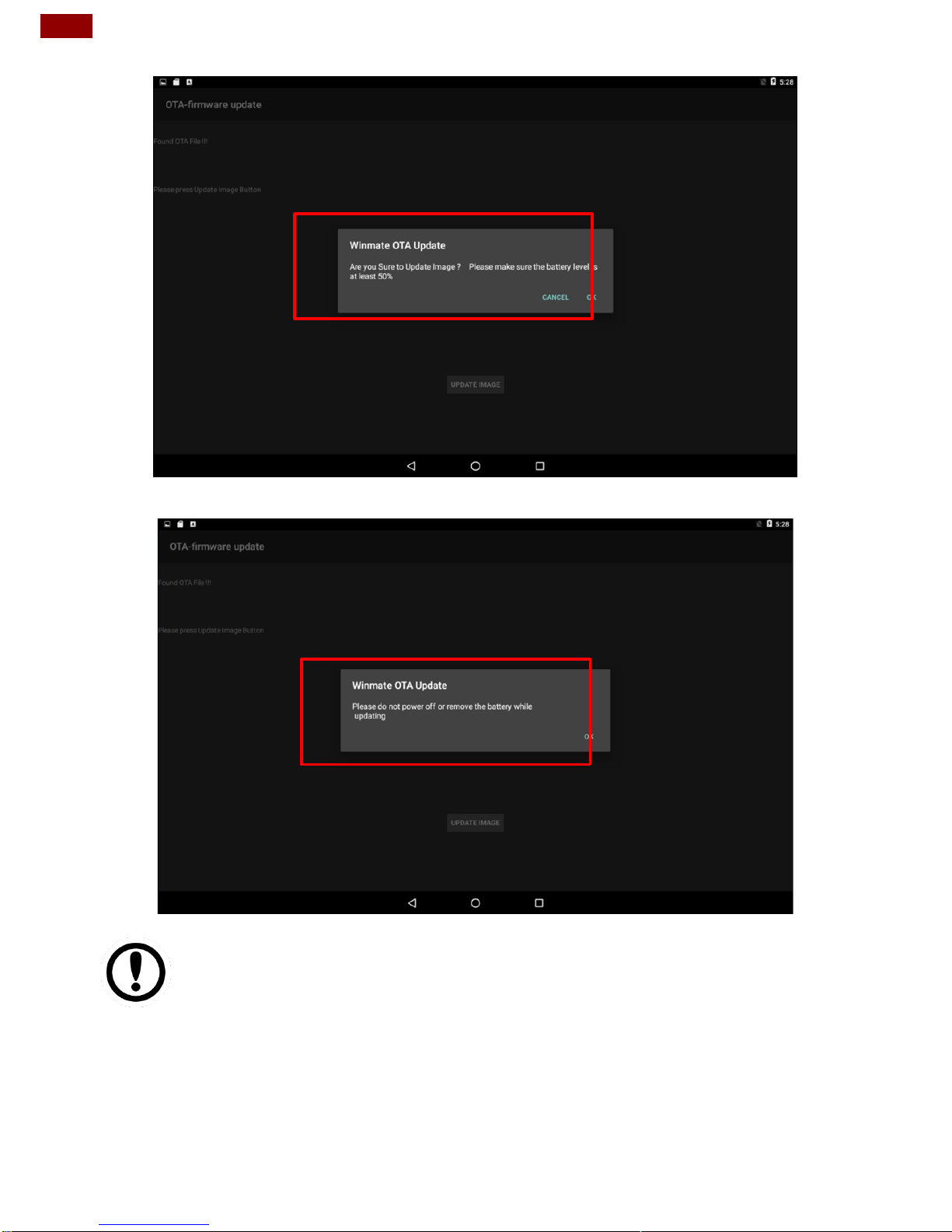
6. Make sure the battery level is at least 50%. Tap OK.
7. Tap OK.
Important:
Do not disconnect the power source!
Do not remove the battery!
Page 45
45
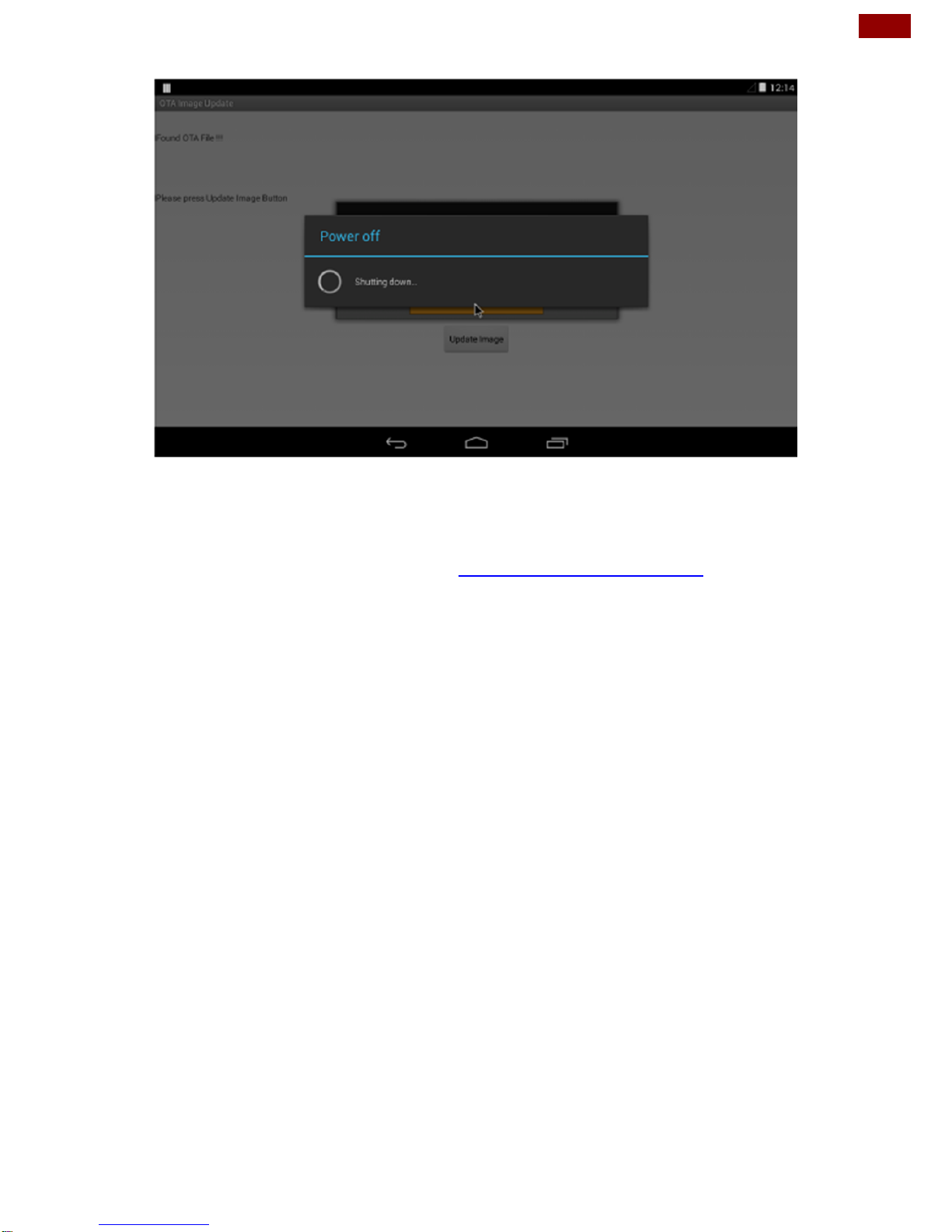
Chapter 4: Software Installation
8. After update the system will automatically restart.
4.5 OS Image Update Guide
Download OS Image update guide from Winmate Download Center
Page 46
46
PT Series Android HMI User Guide
Appendix
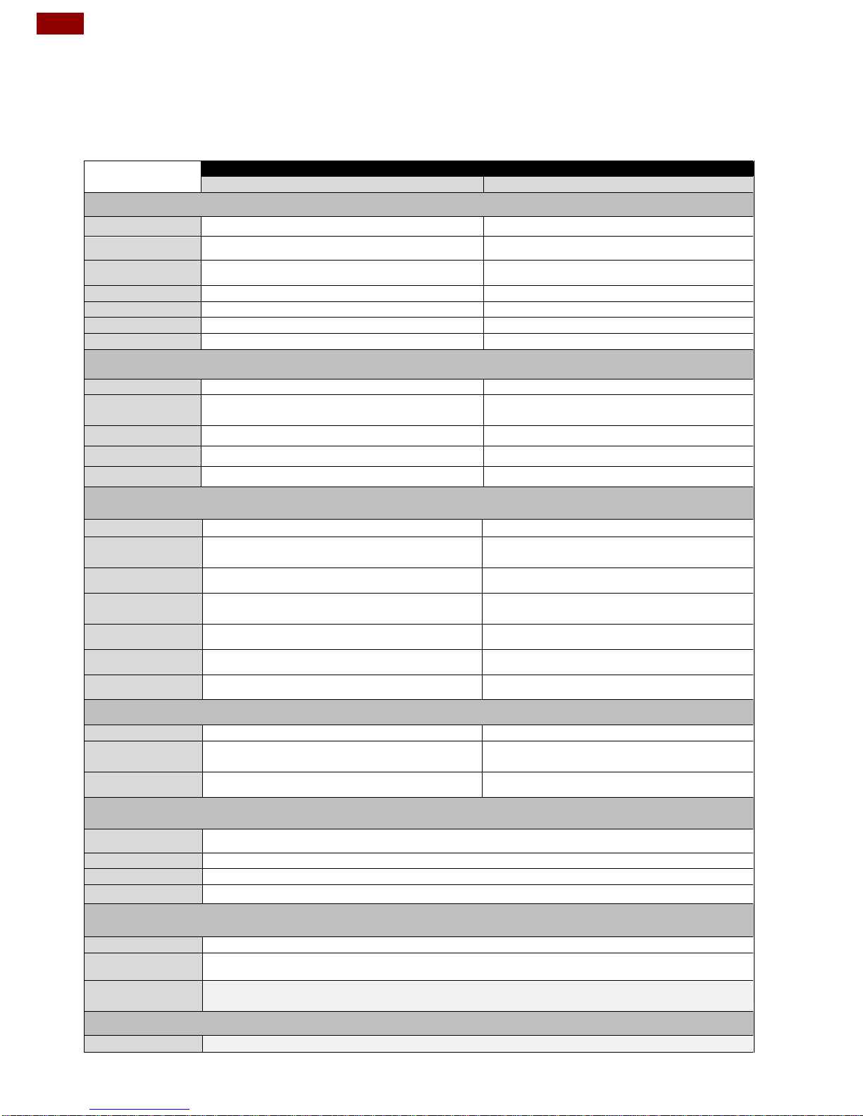
Appendix A: Product Specifications
Model Name
R15FA3S-PTC3
W15FA3S-PTA3
Display
Size
15”
15.6”
Resolution
1024 x 768
1920 x 1080
Brightness
300
300
Contrast Ratio
700:1 (typ.)
800:1 (typ.)
Viewing Angle
~80~80 (H); ~80~80 (V)
-85~85(H);-85~85(V)
Max Colors
16.2M
262K
Touch
Projected capacitive
Projected capacitive
Mechanical
Dimensions
352.5 x 276.7 x 45 (mm)
Mounting
VESA (100 x 100 mm, 75 x 75 mm)
VESA (75 x 75 mm, 100 x 100 mm, 200 x
100mm)
Cooling
Fanless
Fanless
Housing
Plastic casing
Plastic casing
Color
Space grey RAL 7016
White
Interfaces
Power
1 x Terminal block 2-pin
1 x Terminal block 2-pin
Serial Port
1 x RS-232/422/485 (DB9),
1 x CANBus (DB9)
1 x RS-232/422/485 (DB9),
1 x CANBus (DB9)
USB Port
1 x USB 2.0, 1 x USB OTG
1 x USB 2.0, 1 x USB OTG
Ethernet
1 x RJ 45-10/100/1000 Mbps (LAN)
*Optional PoE IEEE 802.3at (25W)
1 x RJ 45-10/100/1000 Mbps (LAN)
*Optional PoE IEEE 802.3at (25W)
Console
1 x Mini USB
1 x Mini USB
SD Card Slot
1 x Micro SD Card Reader
1 x Micro SD Card Reader
Speaker
2 x 1W Speaker
2 x 1W Speaker
Power Requirements
Power Input
12V DC
12V DC
Power
Consumption
13W typical, normal operation
13W typical, normal operation
PoE
Power Device follows IEEE 802.3at (25 W)
Power Device follows IEEE 802.3at (25 W)
System Specifications
Processor
Freescale Cortex® A9 i.MX6 Dual Core, 1GHz (Optional Quad Core)
System Memory
1GB LPDDR3 (Optional 2GB)
Storage
Onboard 16GB eMMC
OS
Android 6.0 (Default), Ubuntu 16.04, Linux 4.1.15, QT 5.5
Environment Considerations
Operating Temp.
0°C to +50°C
Storage Temp.
-10°C to +60°C
Operating
Humidity
10 ~ 95% (Non-condensing, RH)
Certification
Safety
CE, FCC Class A, UL, RoHS Directive 2011/65/EU
Page 47
47
Appendix
Appendix B: Cleaning the LCD Monitor
Before cleaning:
Make sure the device is turned off.
Disconnect the power cable from any AC outlet.
When cleaning:
Never spray or pour any liquid directly on the screen or case.
Wipe the screen with a clean, soft, lint-free cloth. This removes dust and other
particles.
The display area is highly prone to scratching. Do not use ketene type material
(ex. Acetone), Ethyl alcohol, toluene, ethyl acid or Methyl chloride to clear the
panel. It may permanently damage the panel and void the warranty.
If it is still not clean enough, apply a small amount of non-ammonia, non-
alcohol based glass cleaner onto a clean, soft, lint-free cloth, and wipe the
screen.
Don not use water or oil directly on the display screen. If droplets are allowed
to drop on the screen, permanent staining or discoloration may occur.
Appendix C: Technical Support
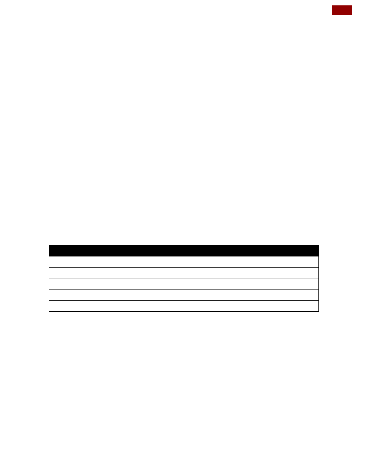
Winmate provides the following Drivers, SDK and Update Guide:
Item
Driver
Description
1
Android Driver
USB Driver
2
Android Driver
USB OTG Driver
3
SDK
Android SDK
4
SDK
Linux SDK
5
Guide
Download OS Image Tool
To find the Drivers and SDK, please refer to the Driver CD that comes in the
package or contact us. Also, you can download drivers from Winmate Download
Center
Page 48

Winmate Inc.
9F, No.111-6, Shing-De Rd., San-Chung District,
New Taipei City 24158, Taiwan, R.O.C
www.winmate.com
Copyright © Winmate Inc. All rights reserved.
 Loading...