

Winmate W07FA3S-PCO1-POE, W10FA3S-PCH2LB, W10FA3S-PCH2AC-PoE, W07FA3S-PCO1AC-POE, R15FA3S-PCC3-PoE Quick Start Manual [en, fr]
...Page 1
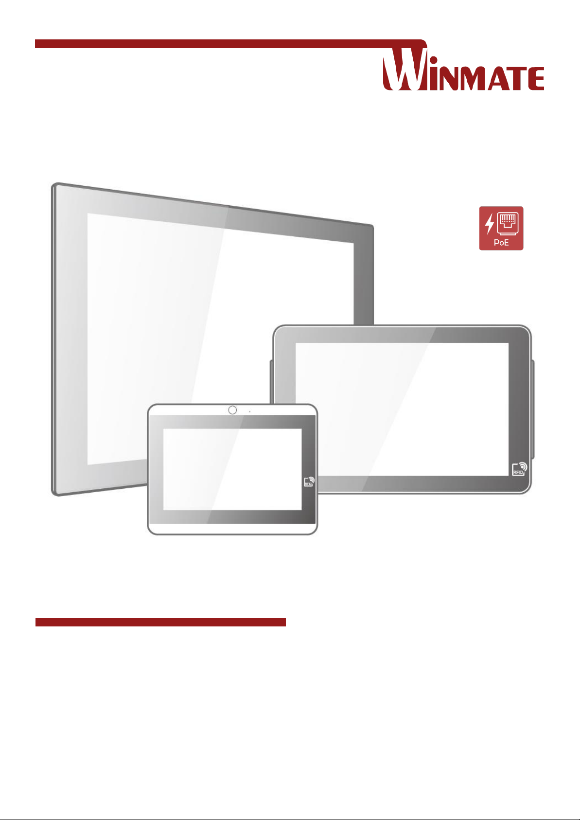
7~15” S-Series HMI
Freescale® Cortex® A9 i.MX6 Dual Core 1 GHz (Optional Quad Core)
Android 6.0
Model No. W07FA3S-PCO1-POE
W07FA3S-PCO1AC-POE
W10FA3S-PCH2AC-PoE
W10FA3S-PCH2-POE
W10FA3S-PCH2LB
R15FA3S-PCC3-PoE
Quick Start Guide
Document Version 1.1
Document Part No. 9152111I1138
Please read these instructions carefully before using this product, and save this manual for future use.
Page 2

2
7~15" S-Series HMI Quick Start Guide
Contents
PREFACE 3
CHAPTER 1: INTRODUCTION 8
1.1 INTRODUCTION 9
1.2 PRODUCT FEATURES 9
1.3 UNPACKING 10
1.4 MECHANICAL DIMENSIONS 11
1.5 CONNECTOR DESCRIPTION 14
CHAPTER 2: GETTING STARTED 15
2.1 CONNECTING THE POWER 16
2.2 CONNECTOR DESCRIPTION 17
CHAPTER 3: MOUNTING 19
3.1 PANEL MOUNT 20
3.2 VESA MOUNT 21
CHAPTER 4: OPERATING THE DEVICE 27
4.1 HOME SCREEN 28
4.2 QUICK SETTINGS 29
4.3 ETHERNET 30
4.4 WINMATE® HOME MANAGER (WHM) 32
4.5 CONFIGURING SERIAL PORT SETTING 36
APPENDIX 38
APPENDIX A: PRODUCT SPECIFICATIONS 38
APPENDIX B: HF RFID READER SPECIFICATIONS 39
Page 3

3
Preface
Preface
Copyright Notice
No part of this document may be reproduced, copied, translated, or transmitted in any form or
by any means, electronic or mechanical, for any purpose, without the prior written permission
of the original manufacturer.
Trademark Acknowledgement
Brand and product names are trademarks or registered trademarks of their respective owners.
Disclaimer
We reserve the right to make changes, without notice, to any product, including circuits and/or
software described or contained in this manual in order to improve design and/or performance.
We assume no responsibility or liability for the use of the described product(s) conveys no
license or title under any patent, copyright, or masks work rights to these products, and make
no representations or warranties that these products are free from patent, copyright, or mask
work right infringement, unless otherwise specified. Applications that are described in this
manual are for illustration purposes only. We make no representation or guarantee that such
application will be suitable for the specified use without further testing or modification.
Warranty
Our warranty guarantees that each of its products will be free from material and workmanship
defects for a period of one year from the invoice date. If the customer discovers a defect, we
will, at his/her option, repair or replace the defective product at no charge to the customer,
provide it is returned during the warranty period of one year, with transportation charges
prepaid. The returned product must be properly packaged in its original packaging to obtain
warranty service. If the serial number and the product shipping data differ by over 30 days, the
in-warranty service will be made according to the shipping date. In the serial numbers the third
and fourth two digits give the year of manufacture, and the fifth digit means the month (e. g.,
with A for October, B for November and C for December).
For example, the serial number 1W18Axxxxxxxx means October of year 2018.
Customer Service
We provide a service guide for any problem by the following steps: First, visit the website of
our distributor to find the update information about the product. Second, contact with your
distributor, sales representative, or our customer service center for technical support if you
need additional assistance.
You may need the following information ready before you call:
Product serial number
Software (OS, version, application software, etc.)
Description of complete problem
The exact wording of any error messages
In addition, free technical support is available from our engineers every business day. We are
always ready to give advice on application requirements or specific information on the
installation and operation of any of our products.
Page 4
4
7~15" S-Series HMI Quick Start Guide
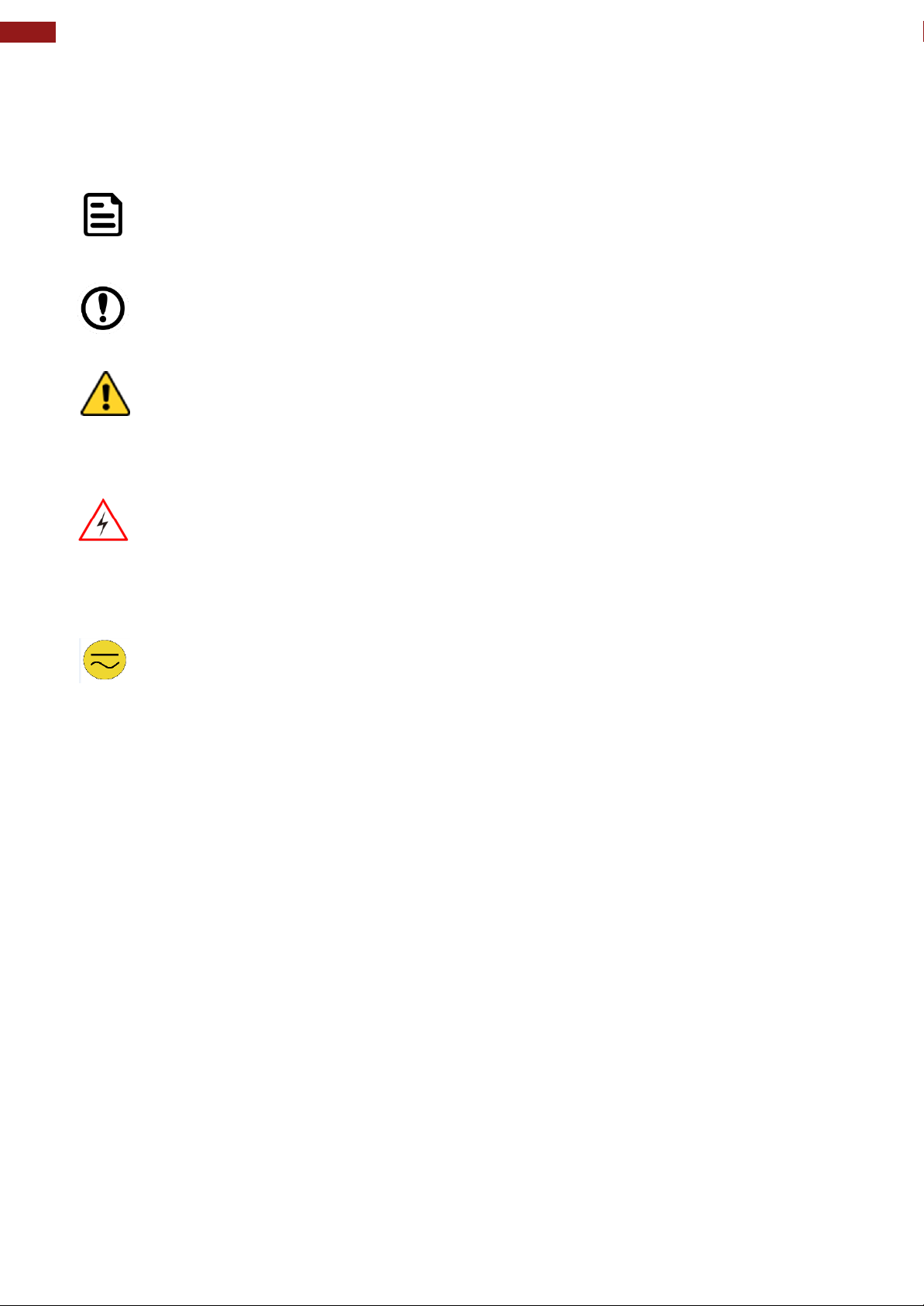
Note:
A note is used to emphasize helpful information
Important:
An important note indicates information that is important for you to know.
Caution/ Attention
A Caution alert indicates potential damage to hardware and explains how to avoid
the potential problem.
Une alerte d’attention indique un dommage possible à l’équipement et explique
comment éviter le problème potentiel.
Warning!/ Avertissement!
An Electrical Shock Warning indicates the potential harm from electrical hazards
and how to avoid the potential problem.
Un Avertissement de Choc Électrique indique le potentiel de chocs sur des
emplacements électriques et comment éviter ces problèmes.
Alternating Current Mise à le terre !
The Protective Conductor Terminal (Earth Ground) symbol indicates the potential
risk of serious electrical shock due to improper grounding.
Le symbole de Mise à Terre indique le risqué potential de choc électrique grave
à la terre incorrecte.
Advisory Conventions
Four types of advisories are used throughout the user manual to provide helpful information or
to alert you to the potential for hardware damage or personal injury. These are Notes,
Important, Cautions, and Warnings. The following is an example of each type of advisory.
Page 5
5
Preface
Warning!/ Avertissement!
Always completely disconnect the power cord from your chassis whenever you
work with the hardware. Do not make connections while the power is on. Sensitive
electronic components can be damaged by sudden power surges. Only
experienced electronics personnel should open the PC chassis.
Toujours débrancher le cordon d’alimentation du chassis lorsque vous travaillez
sur celui-ci. Ne pas brancher de connections lorsque l’alimentation est présente.
Des composantes électroniques sensibles peuvent être endommagées par des
sauts d’alimentation. Seulement du personnel expérimenté devrait ouvrir ces
chassis.
Caution/ Attention
Always ground yourself to remove any static charge before touching the CPU
card. Modern electronic devices are very sensitive to static electric charges. As a
safety precaution, use a grounding wrist strap at all times. Place all electronic
components in a static-dissipative surface or static-shielded bag when they are
not in the chassis.
Toujours verifier votre mise à la terre afin d’éliminer toute charge statique avant
de toucher la carte CPU. Les équipements électroniques moderns sont très
sensibles aux décharges d’électricité statique. Toujours utiliser un bracelet de
mise à la terre comme précaution. Placer toutes les composantes électroniques
sur une surface conçue pour dissiper les charge, ou dans un sac anti-statique
lorsqu’elles ne sont pas dans le chassis.
Safety Information
For your safety carefully read all the safety instructions before using the device. Keep this user
manual for future reference.
Always disconnect this equipment from any AC outlet before cleaning. Do not use liquid or
spray detergents for cleaning. Use a damp cloth.
For pluggable equipment, the power outlet must be installed near the equipment and must
be easily accessible.
Keep this equipment away from humidity.
Put this equipment on a reliable surface during installation. Dropping it or letting it fall
could cause damage.
The openings on the enclosure are for air convection and to protect the equipment from
overheating.
Do not cover the openings.
Before connecting the equipment to the power outlet make sure the voltage of the power
source is correct.
Position the power cord so that people cannot step on it. Do not place anything over the
power cord.
If the equipment is not used for a long time, disconnect it from the power source to avoid
damage by transient over-voltage.
Never pour any liquid into an opening. This could cause fire or electrical shock.
Never open the equipment. For safety reasons, only qualified service personnel should
open the equipment.
All cautions and warnings on the equipment should be noted.
Page 6
6
7~15" S-Series HMI Quick Start Guide
Caution/Attention
Use the recommended mounting apparatus to avoid risk of injury.
Utiliser l’appareil de fixation recommandé pour éliminer le risque de
blessure.
Warning!/ Avertissement!
Only use the connection cords that come with the product. When in doubt,
please contact the manufacturer.
Utiliser seulement les cordons d’alimentation fournis avec le produit. Si vous
doutez de leur provenance, contactez le manufacturier.
Warning!/ Avertissement!
Always ground yourself against electrostatic damage to the device.
Toujours vérifier votre mise à la terre afin que l’équipement ne se décharge
pas sur vous.
*Let service personnel to check the equipment in case any of the following
problems appear:
o The power cord or plug is damaged.
o Liquid has penetrated into the equipment.
o The equipment has been exposed to moisture.
o The equipment does not work well or you cannot get it to work according to
the user manual.
o The equipment has been dropped and damaged.
o The equipment has obvious signs of breakage.
Do not leave this equipment in an uncontrolled environment where the storage
temperature is below -20°C (-4°F) or above 60°C (140°F). It may damage the
equipment.
Cover workstations with approved anti-static material. Use a wrist strap connected
to a work surface and properly grounded tools and equipment.
Use anti-static mats, heel straps, or air ionizer for added protection.
Avoid contact with pins, leads, or circuitry.
Turn off power and input signals before connecting test equipment.
Keep the work area free of non-conductive materials, such as ordinary plastic
assembly aids and Styrofoam.
Use filed service tools, such as cutters, screwdrivers that are conductive.
Always put drivers and PCB’s component side on anti-static foam.
General Guideline
It is recommended to reboot the device when some functions are defect or inactive. If it still can't
solve the problems please contact your dealer or agent.
Page 7
7
Preface
This device complies with part 15 FCC rules.
Operation is subject to the following two conditions:
This device may not cause harmful interference.
This device must accept any interference received including
interference that may cause undesired operation.
This equipment is in conformity with the requirement of the
following EU legislations and harmonized standards. Product also
complies with the Council directions.
Important Information
Federal Communications Commission Radio Frequency Interface Statement
This equipment has been tested and found to comply with the limits for a class "B" digital
device, pursuant to part 15 of the FCC rules. These limits are designed to provide reasonable
protection against harmful interference when the equipment is operated in a commercial
environment. This equipment generates, uses, and can radiate radio frequency energy and, if
not installed and used in accordance with the instruction manual, may cause harmful
interference to radio communications. Operation of this equipment in a residential area is likely
to cause harmful interference in which case the user will be required to correct the interference
at him own expense.
EC Declaration of Conformity
Electromagnetic Compatibility Directive (2014/30/EU)
EN55024: 2010 EN 55022: 2010 Class B
o IEC61000-4-2: 2009
o IEC61000-4-3: 2006+A1: 2007+A2: 2010
o IEC61000-4-4: 2012
o IEC61000-4-5: 2014
o IEC61000-4-6: 2013
o IEC61000-4-8: 2010
o IEC61000-4-11: 2004
EN55022: 2010/AC:2011
EN61000-3-2:2014
EN61000-3-3:2013
Low Voltage Directive (2014/35/EU)
EN 60950-1:2006/A11:2009/A1:2010/A12:2011/ A2:2013
Page 8

8
7~15" S-Series HMI Quick Start Guide
Chapter 1: Introduction
This chapter gives you product overview, describes features and hardware
specification. You will find all accessories that come with the HMI in the
packing list. Mechanical dimensions and drawings included in this chapter.
Page 9

9
Chapter 1: Introduction
1.1 Introduction
Congratulations on purchasing Winmate® S-Series HMI. Interactive and smart automation
systems of intelligent buildings are in a fast growing phase. Winmate® multi-touch S-Series
HMI is suitable for home automation and room management systems.
Flat surface is easy-to-clean and delivers aesthetically pleasing look for any interior. By
connecting to centralized database, it can provide real time update for booking status and
available schedule, or perform as a synchronous display in meetings.
Winmate® S-Series HMI powered by Freescale® Cortex A9 i.MX6 Dual Core processor and
support Android 6.0 operating systems. The HMI device features P-Cap touch-screen. In
addition, the HMI device model supports an exceptional feature - LED Light Bar. With the help
of red, green, blue and orange LED indicators you can see the status of the machine or
processes afar. It significantly reduces power consumption by keeping the display turned off.
1.2 Product Features
Winmate® S-Series HMI features:
7/ 10.1/ 15.6-inch widescreen panel
Projected capacitive multitouch screen
Freescale® Cortex® A9 i.MX6 Dual Core 1 GHz (Optional Quad Core)
Android 6.0 operating system
1 x USB 2.0, 1 x USB OTG, 1 x CANBus, 1 x RS-232/422/485
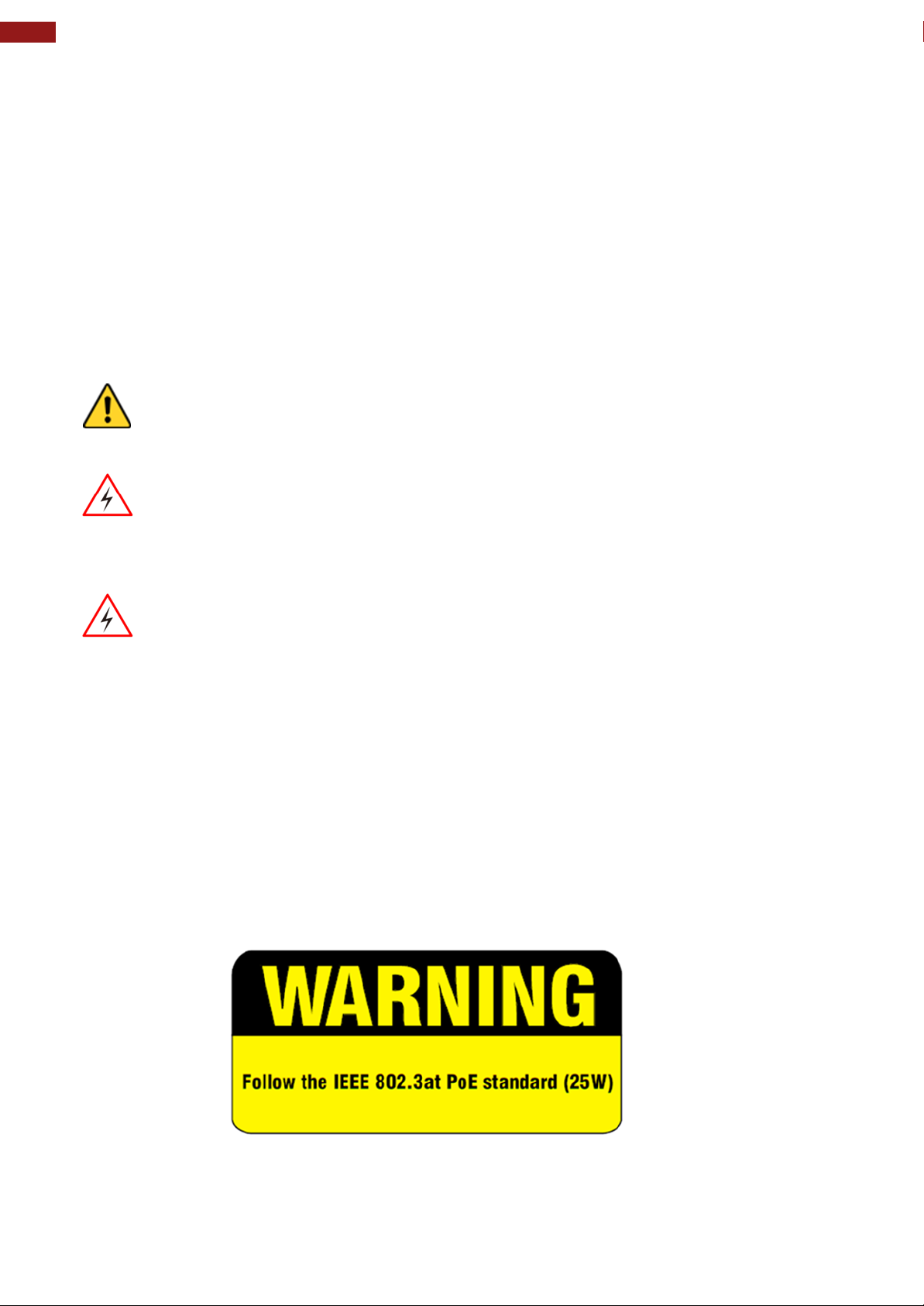
Supports PoE IEEE 802.3at (25 W), IEEE 802.3af (15 W)
Fanless cooling system and ultra-low power consumption
Front IP65 water and dust proof, rear IP22
Light design for machine automation, smart factory and IoT applications
Page 10
10
7~15" S-Series HMI Quick Start Guide
HMI Device
Quick Start Guide
(Hardcopy)
Driver CD & User
Manual
AC Adapter (12V/
50W)
Varies by product
specifications
Part No. 9152111I1138
Part No. 9171111I102P
Part No.
922D050W12VA
Power Cord
3 pin Terminal
Block to DC Jack
VESA Screws
Varies by country
Part No. 94J602G030K0
Part No.913511101145
VESA Desk Stand
PCVS-V1
VESA Desk Stand
LA-100
VESA Wall Mount
Bracket LA-106
Front Side Wall
Mount PCFW-V1
Part No. 99KK00A0000E
Part No. 9B0000000128
Part No. 9B0000000412
Part No. 99KK00A0000C
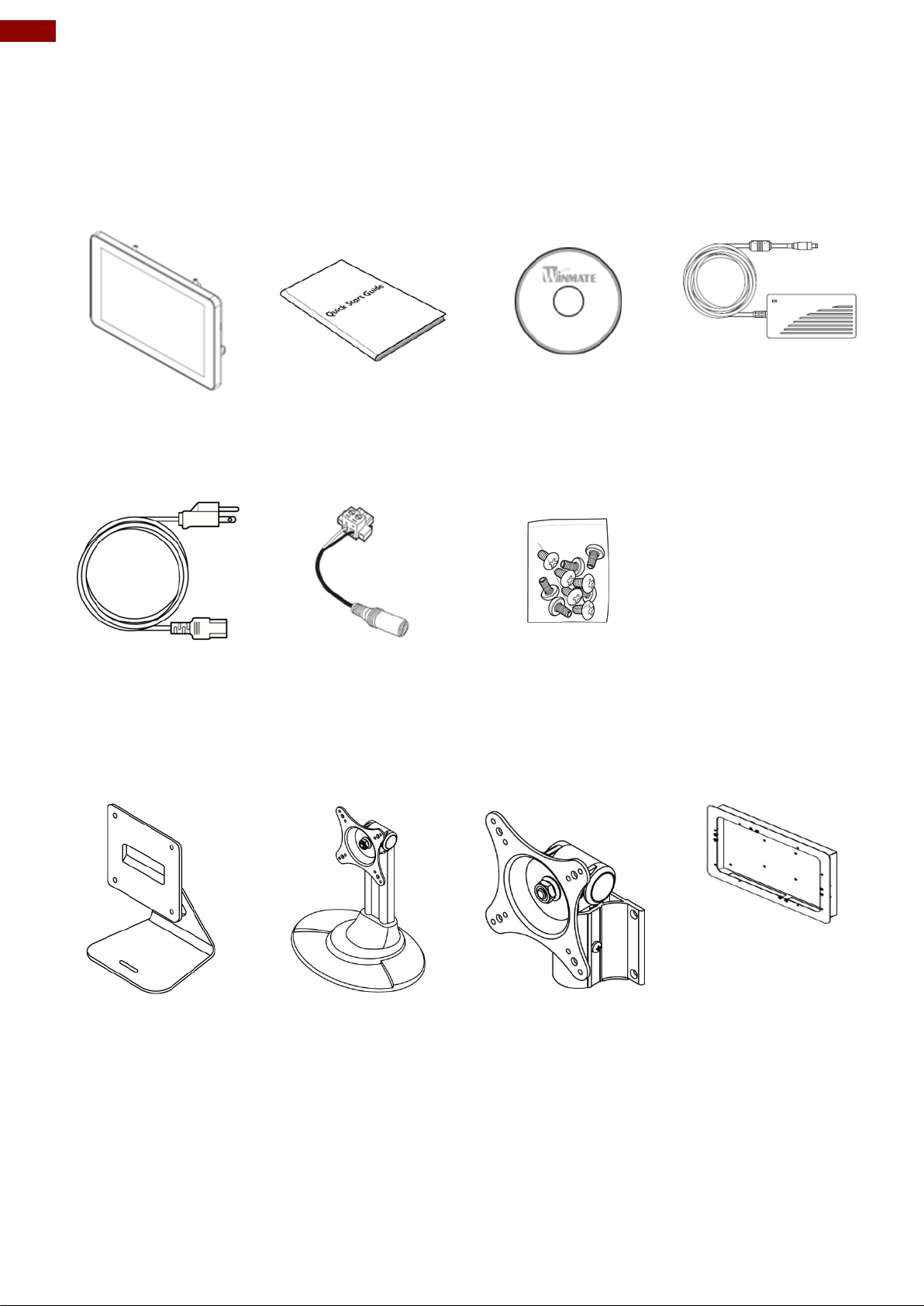
1.3 Unpacking
Carefully remove the box and unpack your HMI device. Please check if all the items listed
below are inside your package. If any of these items are missing or damaged contact us
immediately.
Standard factory shipment list:
Package may include optional accessories based on your order
Page 11
11
Chapter 1: Introduction
№
Description
№
Description
①
Micro SD Card Slot
⑦
9-24V DC
②
LAN/ PoE*
⑧
2MP Front Camera (Optional)
③
USB OTG
⑨
1W Speaker
④
CANBus
⑩
LED Status Light Bar (Only
W07FA3S-PCM1AC-PoE)
⑤
RS-232/422/485
⑪
HF RFID Reader (Optional)
⑥
USB 2.0 x 1
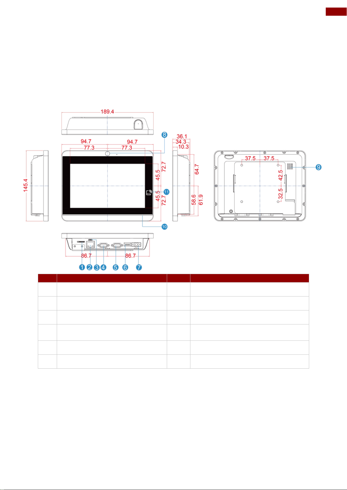
1.4 Mechanical Dimensions
This section describes appearance, connectors’ layout and mechanical dimensions of S-Series
HMI. Notice that this is a simplified drawing and some components are not marked in detail.
Please contact our sales representative if you need further product information.
7-inch, W07FA3S-PCO1-POE/ W07FA3S-PCM1AC-PoE
Unit: mm
Dimensions:189.4 x 145.4 x 36.1
*Power Device (PD): follows IEEE 802.3at (25 W), IEEE 802.3af (15 W)
Page 12
12
7~15" S-Series HMI Quick Start Guide
№
Description
№
Description
①
Mini USB Console(Linux use)
⑥
USB 2.0 x 1
②
Micro SD Card Slot
⑦
12V DC
③
LAN/ PoE*
⑧
2MP Front Camera (Optional)
④
USB OTG
⑨
LED Status Light Bar (Only
W10FA3S-PCH2AC-PoE)
⑤
RS-232/422/485
⑩
1W Speaker
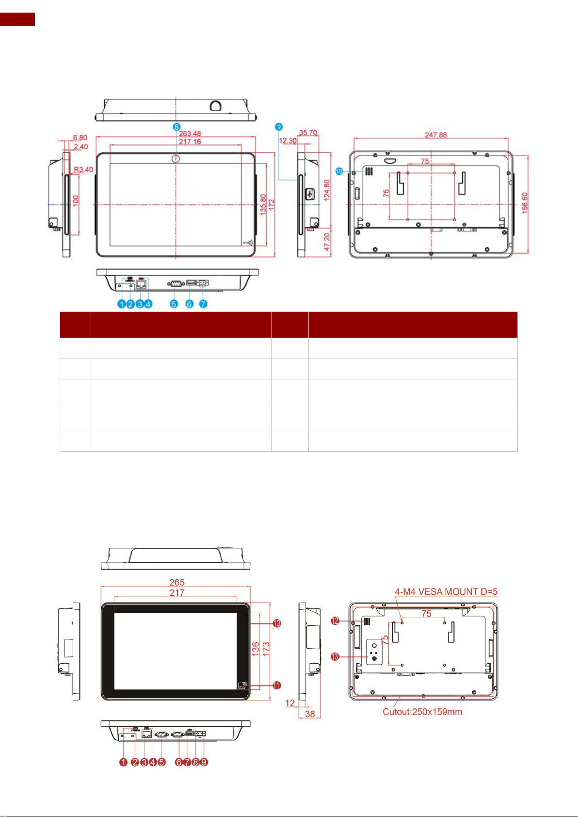
10.1-inch, W10FA3S-PCH2AC-PoE/ W10FA3S-PCH2-POE
Unit: mm
Dimensions:263.48 x 172 x 35.7
*Power Device (PD): follows IEEE 802.3at (25 W), IEEE 802.3af (15 W)
10.1-inch, W10FA3S-PCH2LB
Unit: mm
Dimensions:263.48 x 172 x 35.7
Page 13
13
Chapter 1: Introduction
№
Description
№
Description
①
Mini USB Console(Linux use)
⑦
12V DC
②
Micro SD Card Slot
⑧
Micro HDMI
③
LAN/ PoE*
⑨
12V DC (Phoenix type)
④
USB OTG
⑩
All-Around LED Status Light Bar
⑤
RS-232/422/485
⑪
1W Speaker
⑥
USB 2.0 x 1
⑫
HF RFID (Optional)
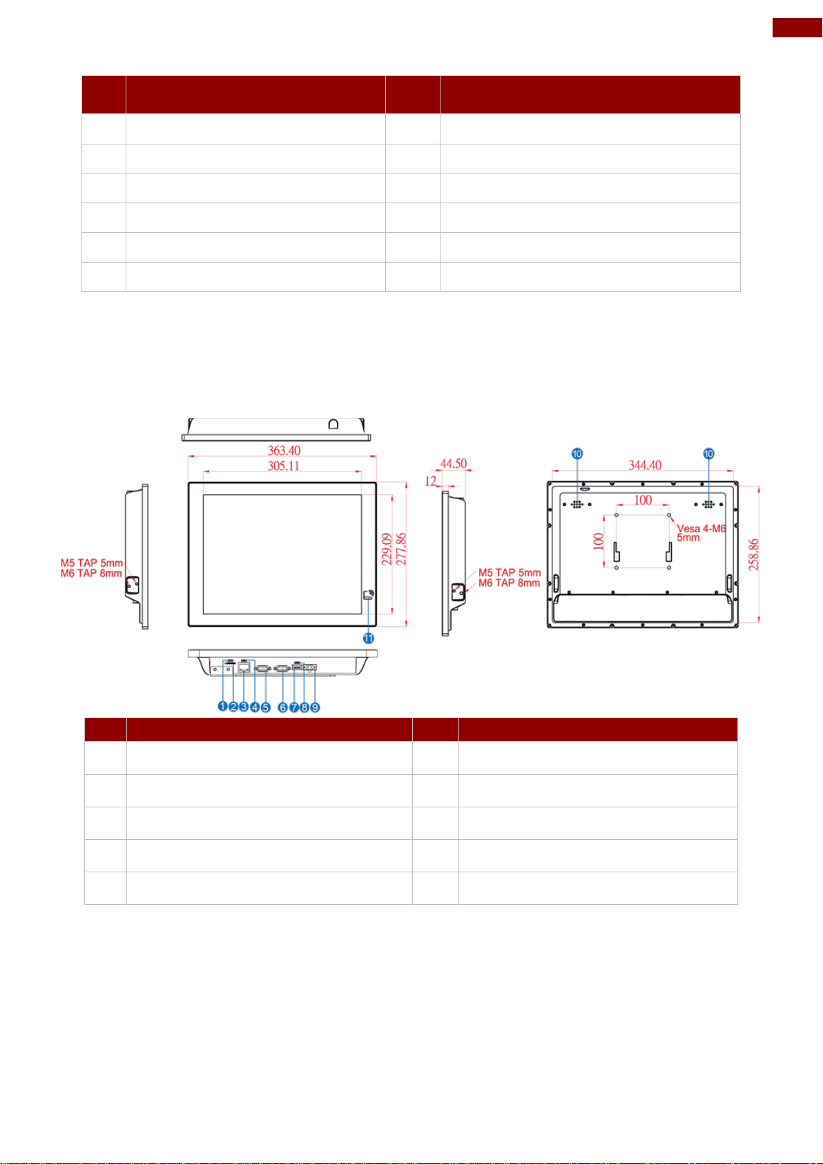
№
Description
№
Description
①
Mini USB Console(Linux use)
⑥
USB 2.0 x 1
②
Micro SD Card Slot
⑦
12V DC
③
LAN/ PoE
⑧
1 Watt Speaker
④
USB OTG
⑨
HF RFID Reader (Optional)
⑤
RS-232/422/485
*Power Device (PD): follows IEEE 802.3at (25 W), IEEE 802.3af (15 W)
15-inch, R15FA3S-PCC3-PoE
Unit: mm
Dimensions:363.4 x 277 x 86 x 44.5
*Power Device (PD): follows IEEE 802.3at (25 W), IEEE 802.3af (15 W)
Page 14
14
7~15" S-Series HMI Quick Start Guide
Note:
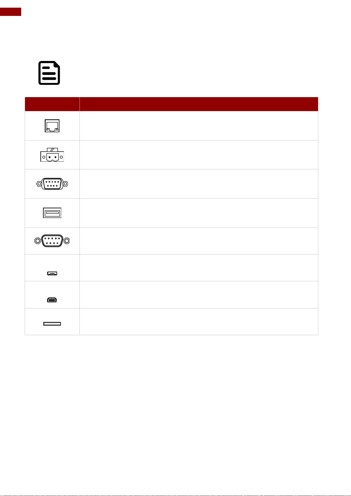
Notice that input and output connectors vary by product size and specifications.
Item
Description
RJ45 – Connects HMI device to Ethernet network. Supports PoE for
power transmission in network equipment, via network UTP cable,
together with data.
Terminal Block – Provides power to the HMI device, accepts 12V DC.
Example: AC cord or DC power supply. If both are provided, choose only
one.
RS-232/422/485 – Connects external devices to HMI device.
Example: A barcode reader or scanner to HMI device.
USB 2.0- Connects USB 2.0 compatible devices to HMI device.
Example: A printer to HMI device.
CANBus – Transmits video from HMI device to external monitor.
Example: An external monitor to HMI device.
USB OTG – Connect to PC for client use and update OS Image.
Console Port – Connect to PC for client use and updates in Linux
system.
MicroSD Card Slot – Insert microSD card to expand the storage.
1.5 Connector Description
Terminal interfaces are located on the bottom side of the HMI device.
Terminal interfaces description:
Page 15

15
Chapter 2: Getting Started
Chapter 2: Getting Started
This chapter tells you important information on power supply, adapter and
precautions tips. Pay attention to power considerations.
Page 16
16
7~15" S-Series HMI Quick Start Guide
Note:
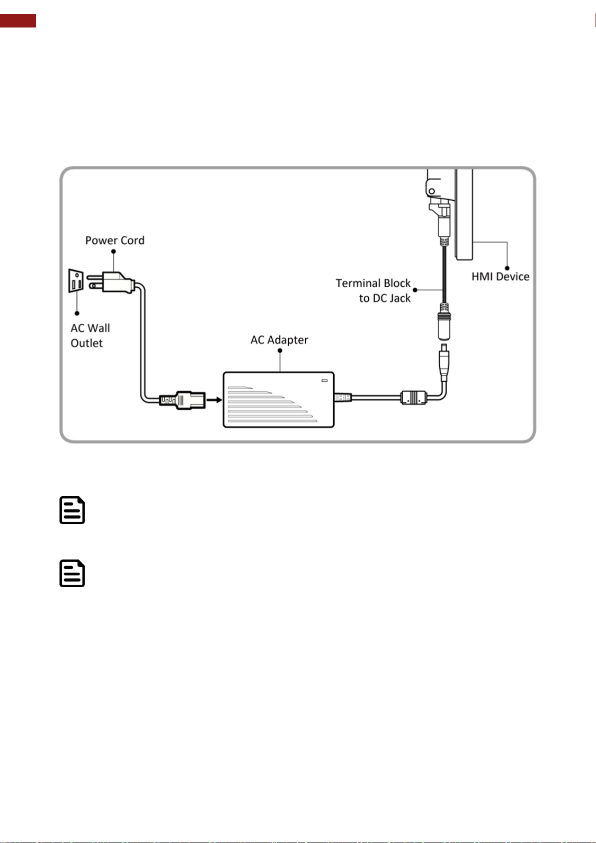
Based on the model, terminal block connector may be located either on the bottom
or on the rear side of the HMI device.
Note:
Power cords vary in appearance by region and country.
2.1 Connecting the Power
Installation Instruction:
1. Connect a 2-pin terminal block to the HMI connector.
2. Connect the other side of the terminal block to the AC adapter.
3. Connect the AC adapter to the power cord.
4. Plug in the power cord to a working AC wall outlet. The device will boot automatically.
Page 17
17
Chapter 2: Getting Started
Important
Power Device (PD): IEEE 802.3at (25 W), IEEE 802.3af (15 W)
Voltage
Please check product
specifications before connecting
to the power source.
Pin №
*RS-232
RS-422
RS-485
1
DCD
TxD-
D-
2
RXD
TxD+
D+ 3 TXD
RxD+
NC
4
DTR
RxD-
NC 5 GND
GND
GND
6
DSR
NC
NC 7 RTS
NC
NC
8
CTS
NC
NC
9
RI
NC
NC
Pin №
Signal Name
Pin №
Signal Name
1
TX1+
2
TX1-
3
TX2+
4
TX2-
5
TX3+
6
TX3-
7
TX4+
8
TX4-
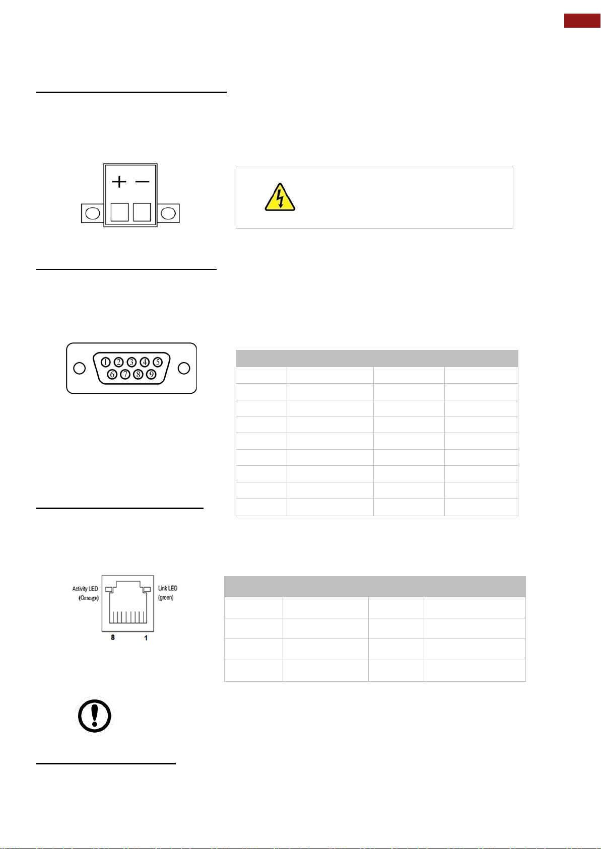
2.2 Connector Description
2.2.1 Power Input Connector
The DC power source input of the S-Series HMI is a 2 pin terminal block connector that
supports 9-24V DC or 12V DC power input depending on your model.
Pin assignment and connector description of terminal block connector.
2.2.2 Serial Port Connector
The S-Series HMI has one serial port connector to connect your HMI to external devices such as
mouse, modem or printer. You can configure serial port settings via APP.
Pin assignment and connector description of serial port connector.
*Default setting: RS-232
2.2.3 Ethernet Connector
The S-Series HMI device supports one
RJ45 10/100/1000 Mbps Ethernet interface for connecting to the internet.
Pin assignment and connector description of RJ45 connector.
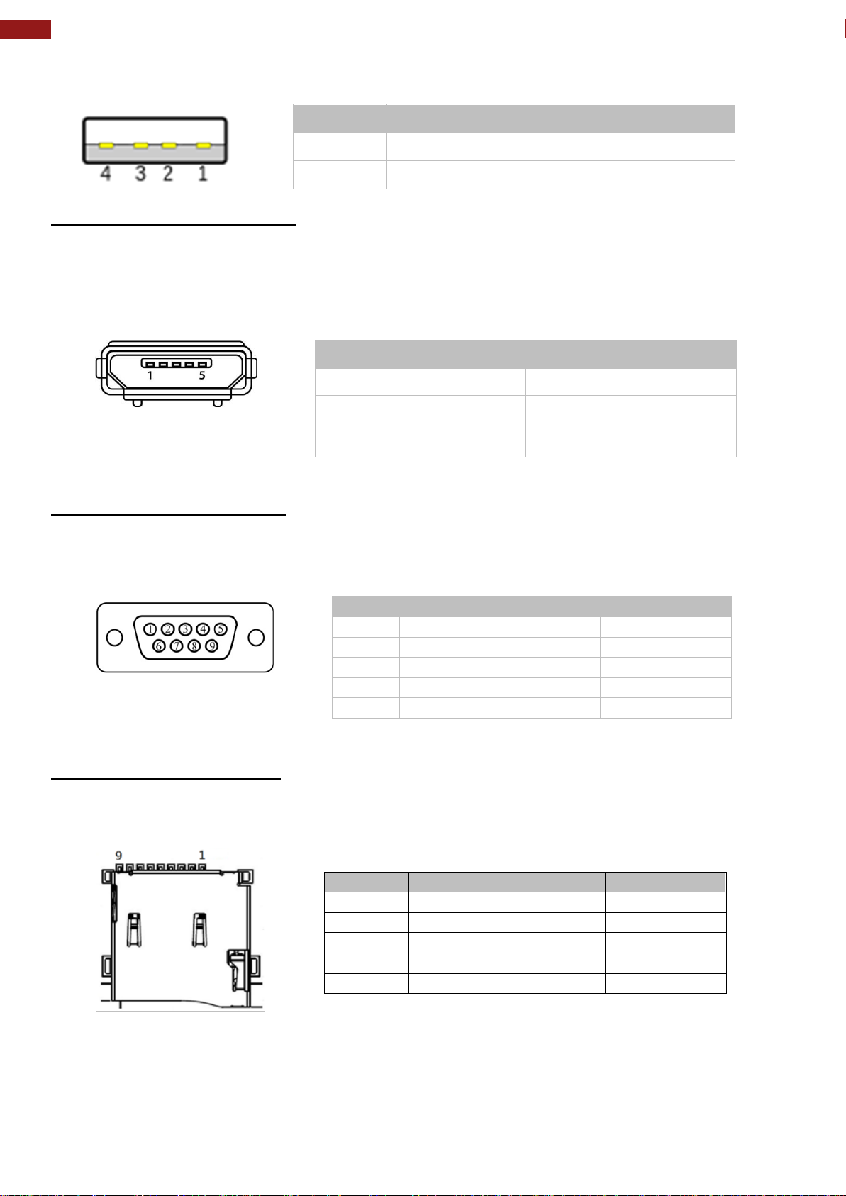
2.2.4 USB Connector
Use USB A Type (USB 2.0) connector to connect your HMI device to other USB 2.0 compatible
devices.
Page 18
18
7~15" S-Series HMI Quick Start Guide
Pin №
Signal Name
Pin№
Signal Name
1
+5V
2
USB_D-
3
USB_D+
4
GND
Pin №
Signal Name
Pin №
Signal Name
1
+5V
2
USB_OTG_D-
3
USB_OTG_D+
4
USB_OTG_ID
5
GND
Pin №
Signal Name
Pin №
Signal Name
1
GND
2
CAN_L
3
GND
4
NC
5
NC 6 NC
7
CAN_H
8
GND
9
+5V/NC
Pin №
Signal Name
Pin №
Signal Name
1
DATA2
2
DATA3
3
CMD
4
+3.3V
5
CLK
6
GND
7
DATA0
8
DATA1
9
Card_Det
Pin assignment and connector description of USB connector.
2.2.5 USB OTG Connector
Use USB OTG connector to connect the panel PC to other USB On-The-Go compliant devices
such as flash drives, digital cameras, mice or keyboards. Use USB OTG cable to install software
on the panel PC.
Pin assignment and connector description of USB OTG connector
2.2.6 CANBus Connector
The connector secured to the motherboard with two screws.
Pin assignment and connector description of CANBus connector
2.2.7 Micro SD Card Slot
Insert microSD card to microSD card slot to extend the memory of your HMI device.
Pin assignment and connector description of micro SD card slot.
Page 19

19
Chapter 3: Mounting
Chapter 3: Mounting
This chapter provides mounting guide for all available mounting options. Pay
attention to cautions and warning to avoid any damages.
Page 20
20
7~15" S-Series HMI Quick Start Guide
Size
Wall Cutout
Screw Hole Diameter
7”
249 x 157.6 mm
M3 x 4mm
10.1”
249 x 157.6 mm
M3x4 mm
15.6”
360 x 292 mm
M3x5 mm
Note:
Make sure that the eight holes on gasket can fit in the mounting
holes on the device.
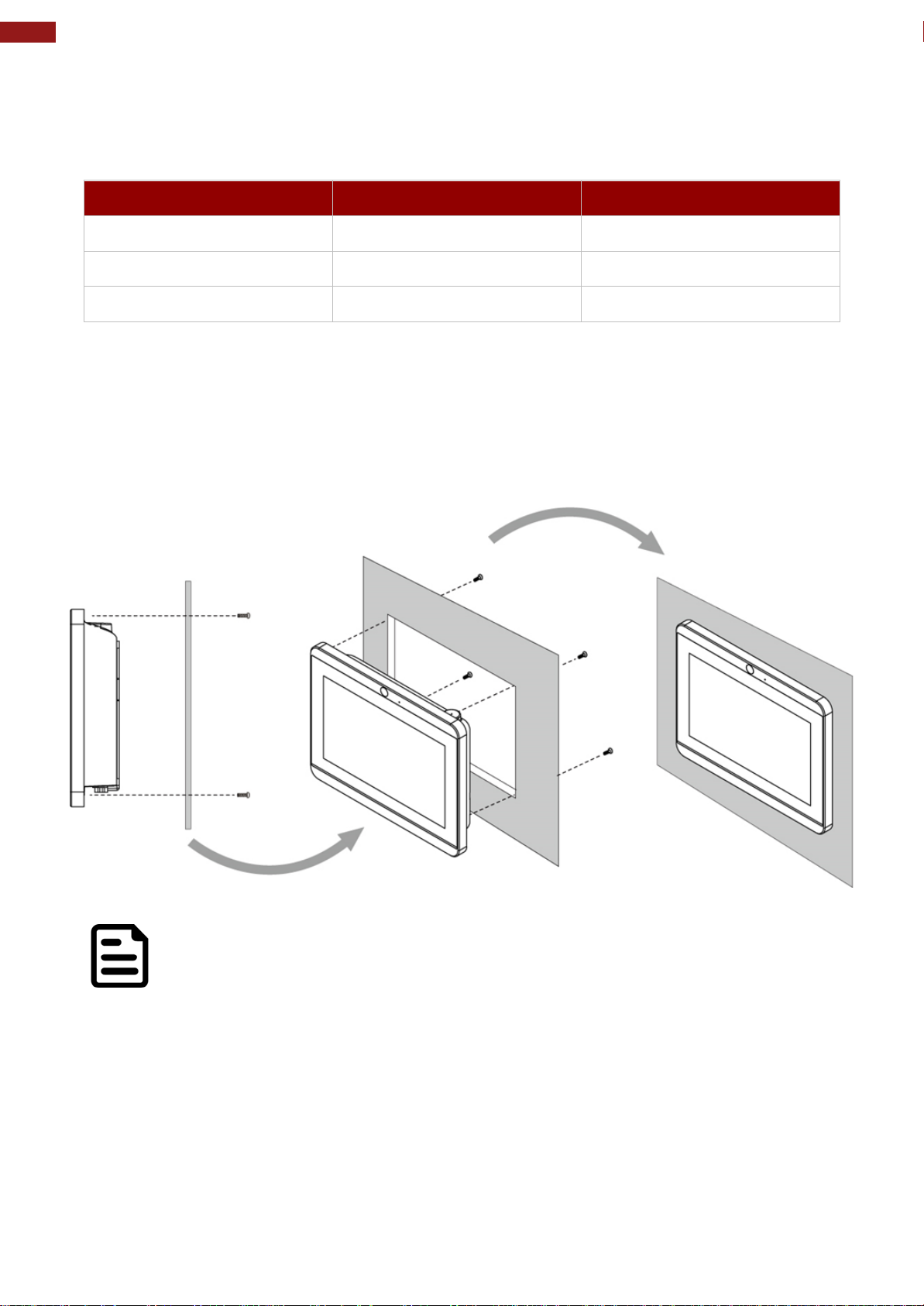
3.1 Panel Mount
Panel mount mounting solutions is suitable for many applications where HMI should be
embedded in the machine. With this mounting solution flat surface leave no bezel in the front.
Installation Instruction
1. Prepare a fixture for the specific dimensions of the device.
2. Cut a hole on a sub frame or panel according to the cutout dimensions.
3. Install the device properly onto the cutout area of the sub frame or panel with the sides of
the front bezel.
4. Fix the device to fixture with eight Philips M3x4 screws.
Page 21
21
Chapter 3: Mounting
3.2 VESA Mount
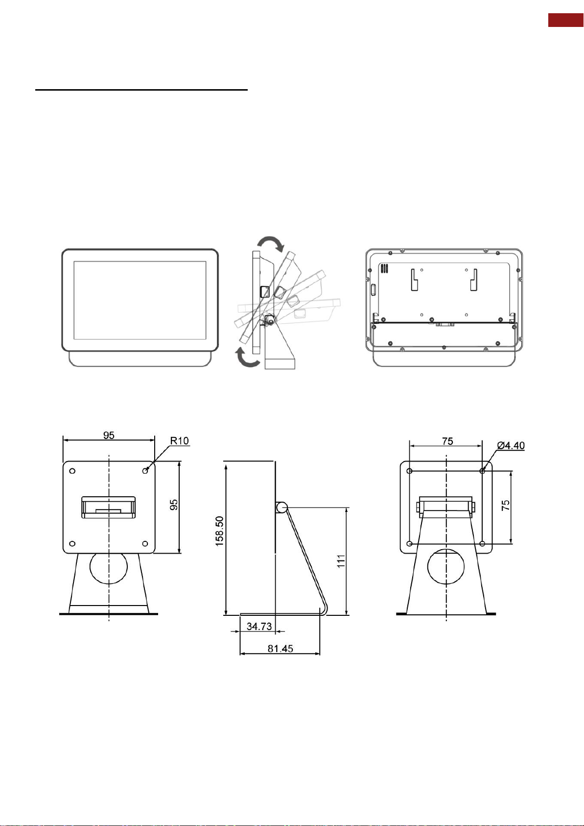
3.2.1 VESA Desk Stand PCVS-V1
The HMI device can be installed on a desk with the stand. You can purchase desk stand as an
optional accessory.
Model Name PCVS-V1
Part No. 99KK00A0000E
Installation Instruction
Use provided Philips M4x5 screws to fix the desk stand to VESA holes on the back cover of the
device.
Dimensions
Page 22
22
7~15" S-Series HMI Quick Start Guide
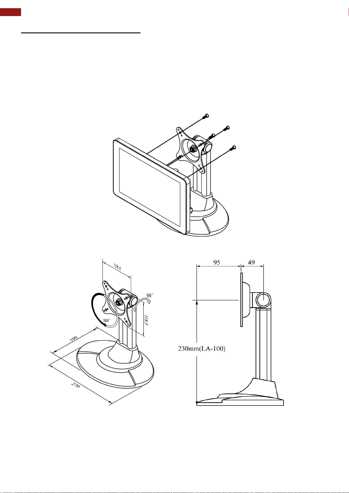
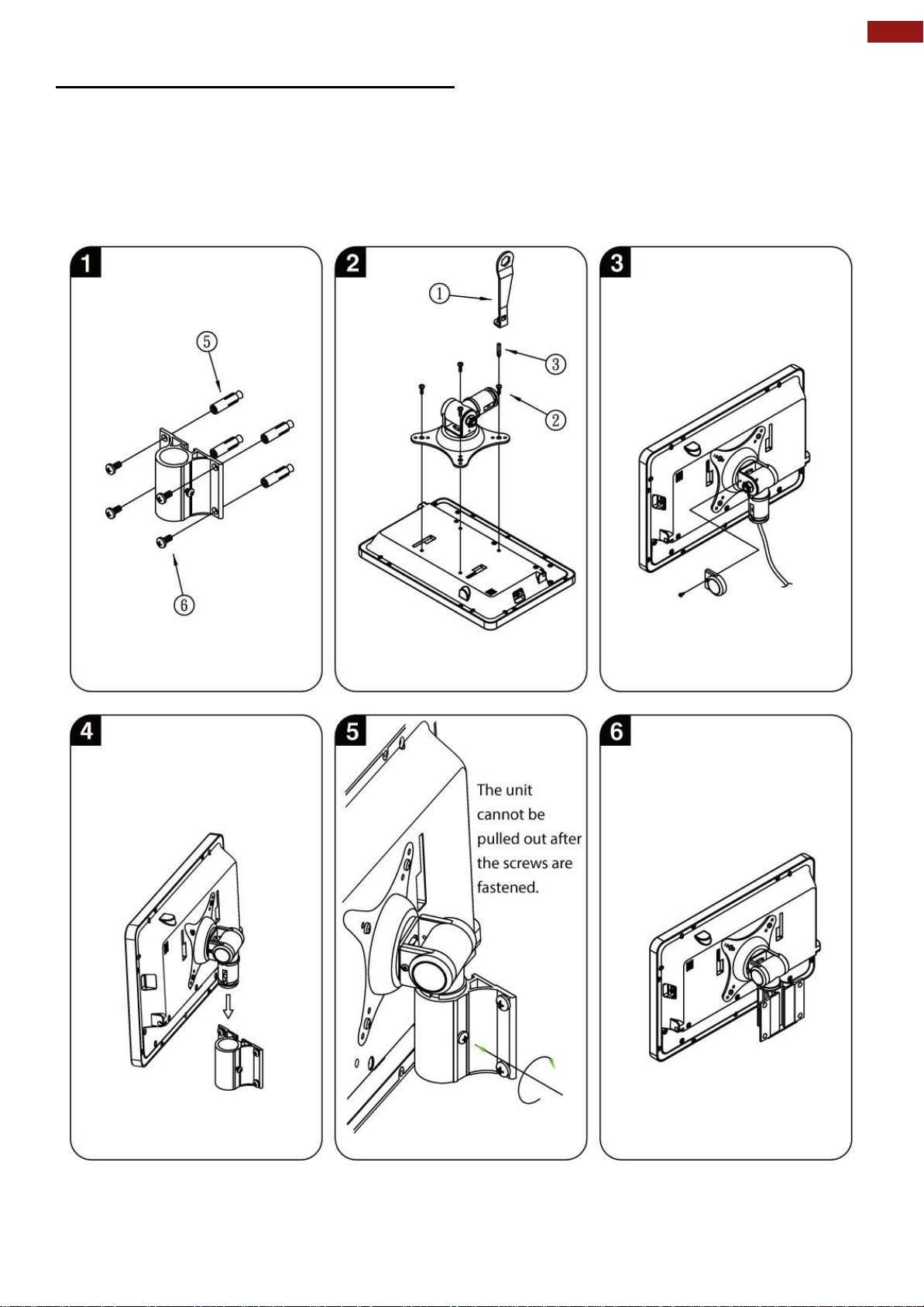
3.2.2 VESA Desk Stand LA-100
The HMI device can be installed on a desk with the stand. You can purchase desk stand as an
optional accessory.
Model Name: LA-100
Part No. 9B0000000128
Installation Instruction
Use provided Philips M4x5 screws to fix the desk stand to VESA holes on the back cover of the
device.
Dimensions
Page 23
23
Chapter 3: Mounting
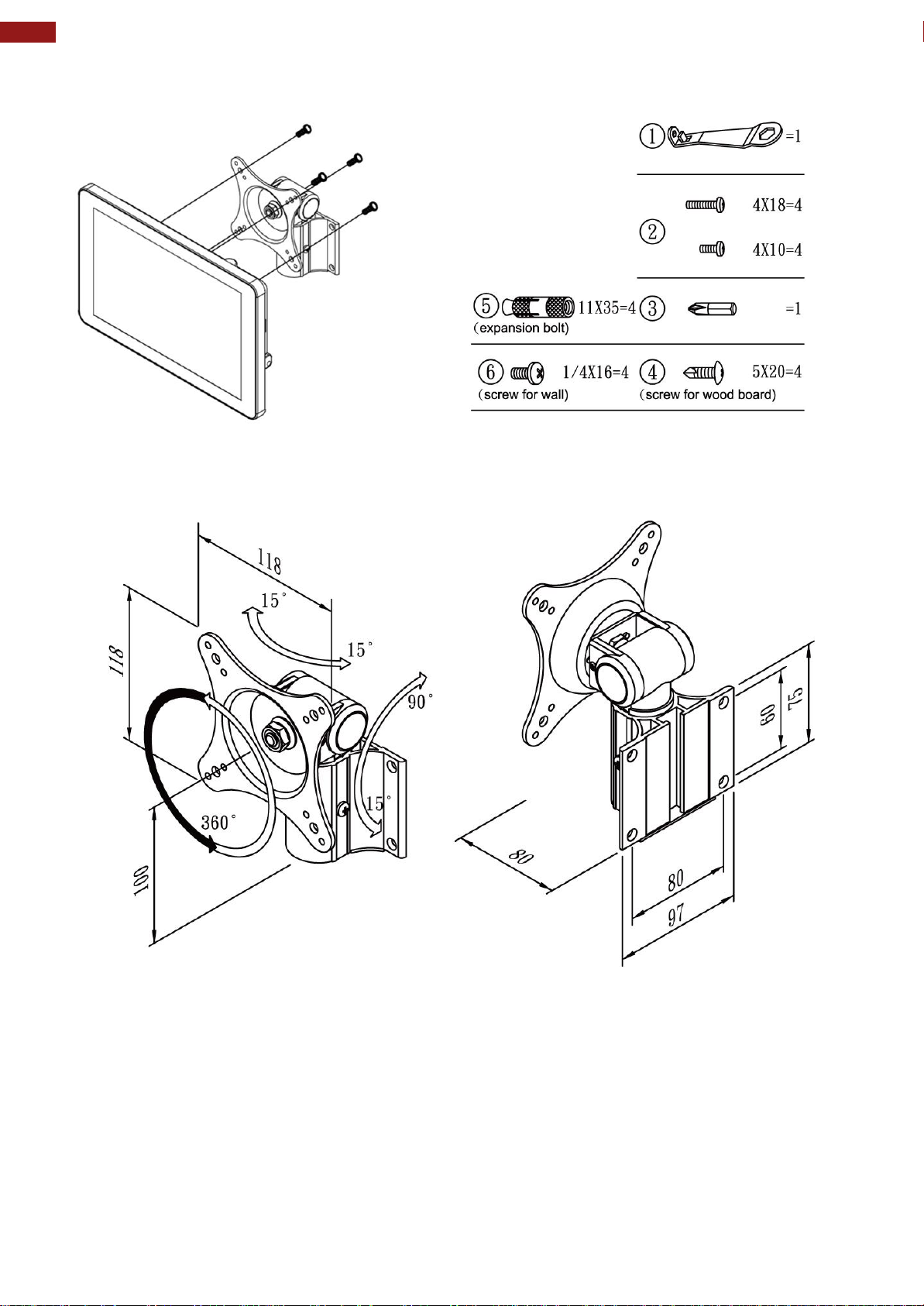
3.2.3 VESA Wall Mount Bracket LA-106
The HMI device can be installed on a desk with the stand. You can purchase desk stand as an
optional accessory.
Model Name LA-106
Part No. 9B0000000412
Installation Instruction
Page 24
24
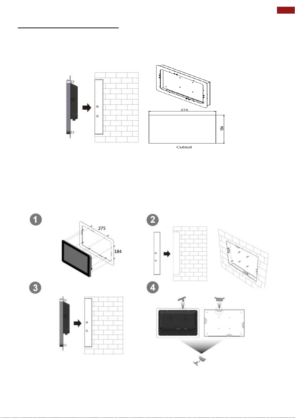
7~15" S-Series HMI Quick Start Guide
Accessories
Dimensions
Page 25
25
Chapter 3: Mounting
3.2.4 Front Side Wall Mounting
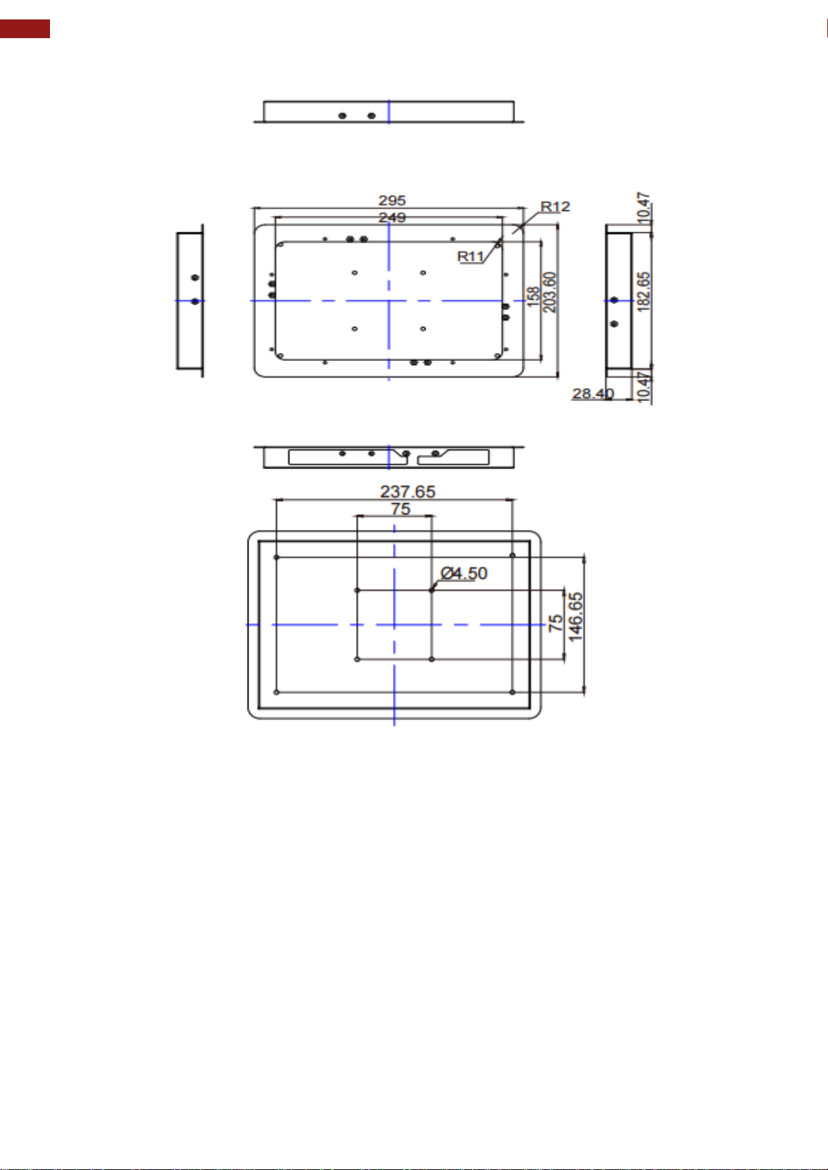
You can purchase Front Side Wall Mount Bracket from Winmate as an optional accessory to
10.1” S-Series HMI.
Model Name PCFW-V1
Part No. 99KK00A0000C
Mounting Instruction
1. Cut a hole in the wall according to the cutout dimensions.
2. Attach the bezel with clips to the device; fix the bezel with Philips M4x5 screws.
3. Connect the device to the power source with the power cord.
4. Install the device properly onto the in-wall cut-out area;
fix the device using the clips.
Page 26
26
7~15" S-Series HMI Quick Start Guide
Dimensions
Page 27

27
Chapter 4: Operating the Device
Chapter 4: Operating the Device
In this chapter you will find instructions on how to operate the HMI device.
Page 28
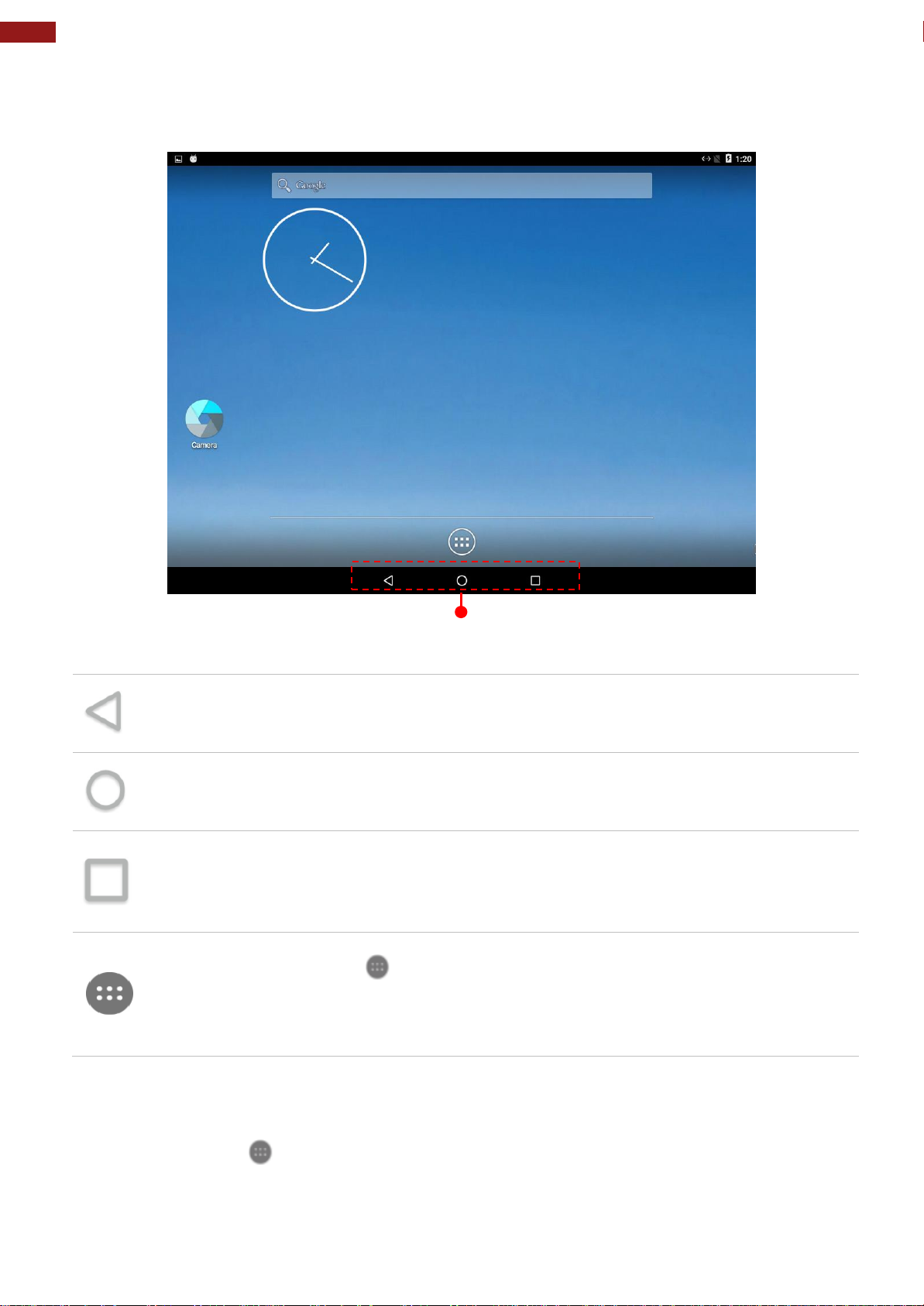
28
7~15" S-Series HMI Quick Start Guide
Back
Opens the previous screen you were working in, even if it was in a different app. Once you
back up to the Home screen, you can’t go back any further.
Home
Returns to the Home screen. To get suggestions based on the screen you’re currently
viewing, touch & hold this button.
Overview
Opens a list of thumbnail images of screens you’ve worked with recently. To open one,
touch it. To remove a screen from the list, swipe it left or right or touch the X.
Your apps
To see all your apps, touch in the Favorites tray on any Home screen. This is where you
can see all your apps, including those that come with your phone or tablet and those you
downloaded on Google Play. You can move app icons to any of your Home screens. The
apps you’ve used most recently appear in the first row.
Navigation Buttons
4.1 Home Screen
Your device runs on Android 7.1 Operation System (Default).
To add an app to a Home screen:
1. Go to the Home screen where you want to place the app.
2. Touch All Apps .
3. Swipe from left to right to find the app you want.
4. Touch & hold the app until the Home screen appears, slide it into place, and lift your
finger.
Page 29
29
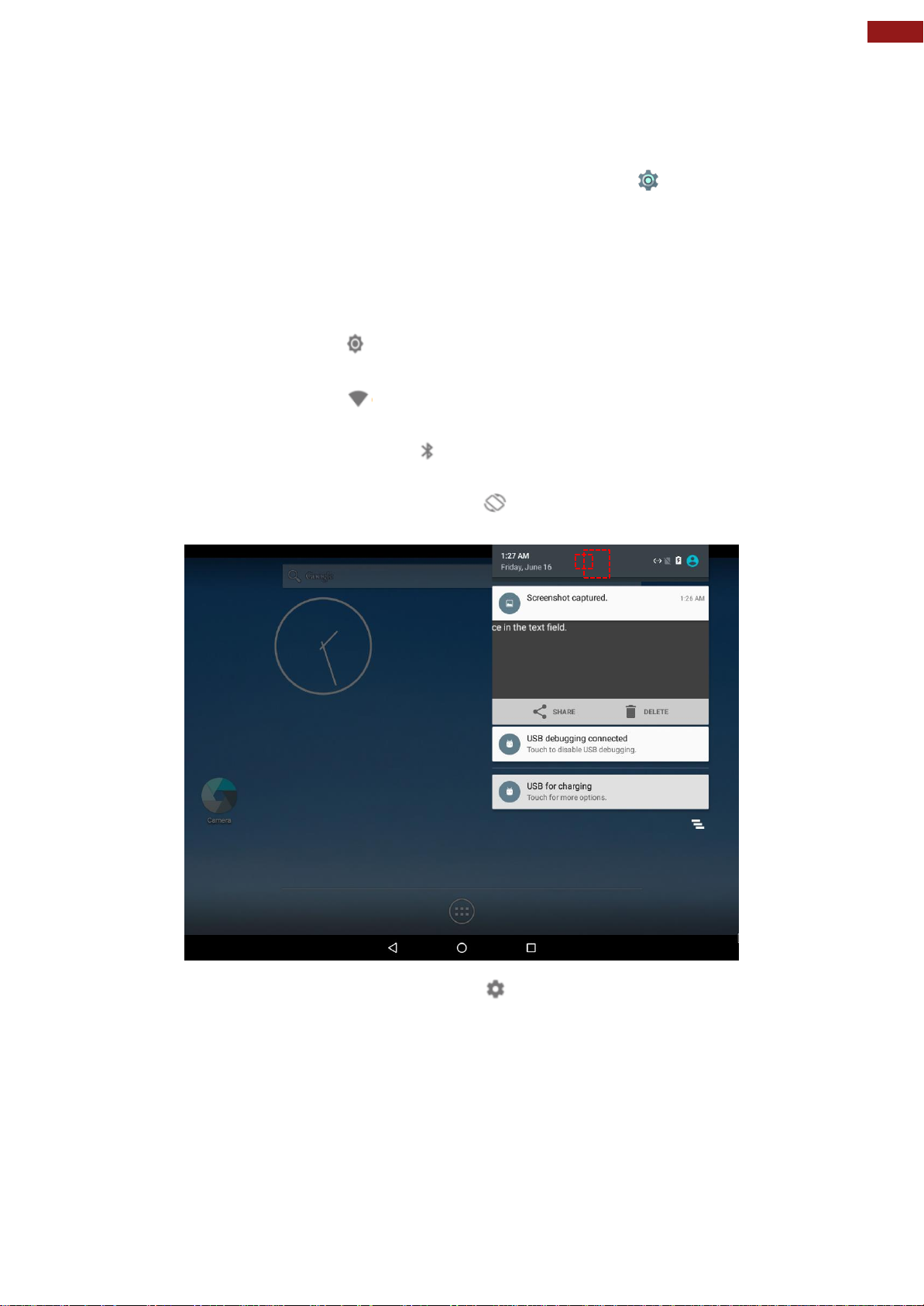
Chapter 4: Operating the Device
Use Quick Settings to easily change frequently used settings, like turning on
Wi-Fi. To open Quick Settings, swipe down from the top of the screen with two
fingers. To change a setting, just touch the icon:
Display brightness: Slide to lower or increase the brightness of
your screen.
Wi-Fi network: Turn Wi-Fi on or off or open the Wi-Fi settings
menu.
Bluetooth settings: Turn Bluetooth on or off or open the Bluetooth
settings menu.
Auto-rotate: Lock your device’s orientation in portrait or landscape
mode.
4.2 Quick Settings
You can open your device’s Settings app from the All Apps screen or from Quick Settings.
For example, to change notification sounds, and volume go to Settings > Device > Sound to
change the volume.
Open the main Settings menu by touching Settings at the top right.
Page 30
30
7~15" S-Series HMI Quick Start Guide
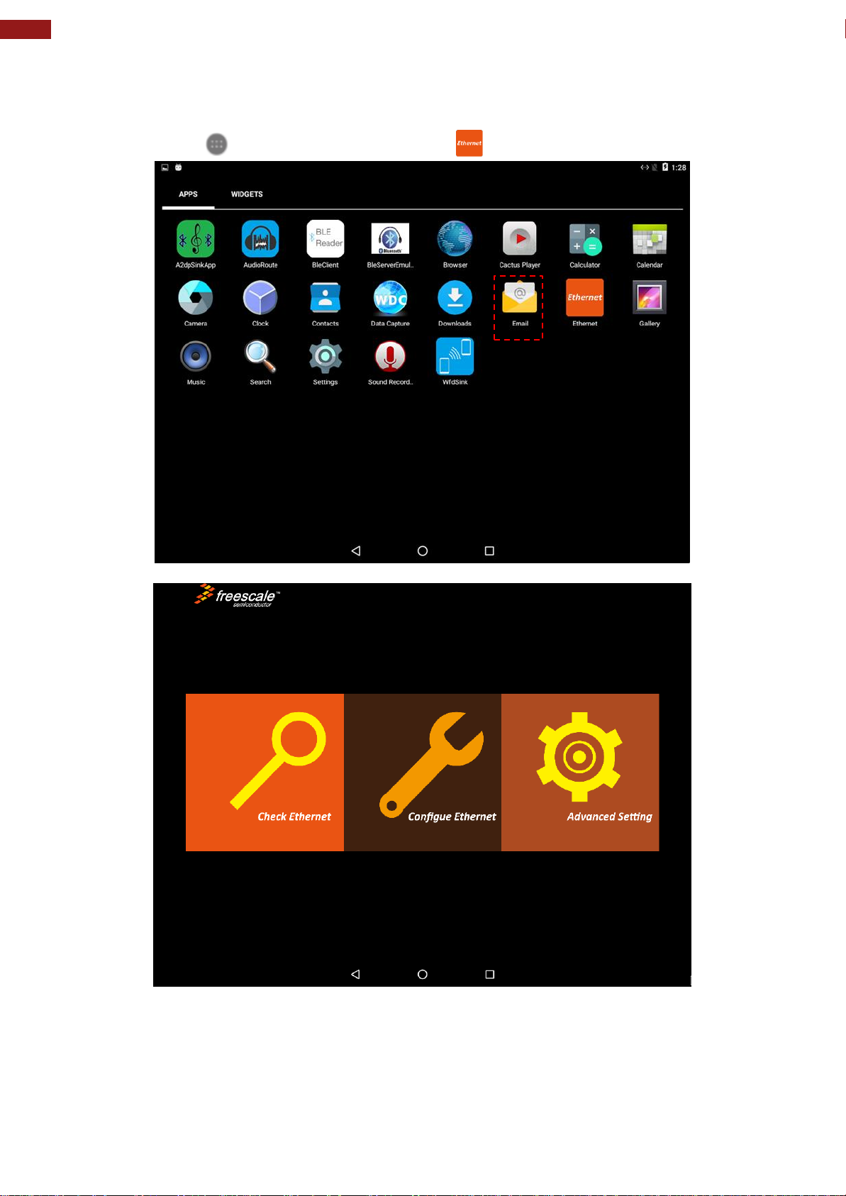
4.3 Ethernet
1. Connect Ethernet Cable to the HMI.
2. Touch All APPS icon, and the open Ethernet application.
3. Ethernet APP main menu appears
Page 31
31
Chapter 4: Operating the Device
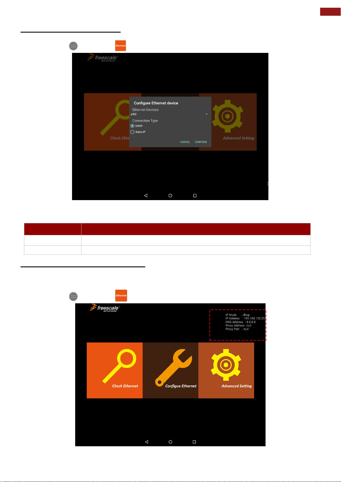
Setting
Description
DHCP
The device automatically capture IP-address from the router
Static IP
Allows to manually set up IP-address, DNS, Network and Gateway
4.3.1 Configuring Ethernet
Go to All Apps > Ethernet > Configure Ethernet
*Ethernet OFF is set by default. Swipe Ethernet ON to activate Ethernet connection.
Connection Type
4.3.2 Checking Ethernet Settings
To check Ethernet settings:
Go to All Apps > Ethernet > Check Ethernet
Ethernet settings menu appears on the top right side of the desktop.
Page 32
32
7~15" S-Series HMI Quick Start Guide
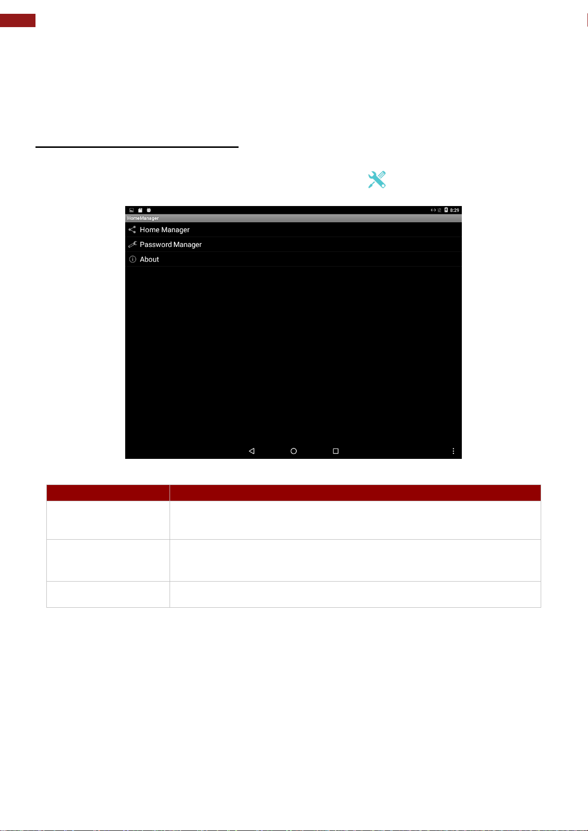
Menu
Description
Home Manager
Set which app you want to run up automatically after booting
Password Manager
Set the WHM password (Default password is “0000”).
About
Displays information about Home Manager
4.4 Winmate® Home Manager (WHM)
Winmate® S-Series HMI comes with preinstalled APP called Winmate® Home Manager (WHM)
which let the device manager to lock the launcher then the user can only use one application
assigned by the device manager.
4.4.1 How to Lock Applications
To lock applications:
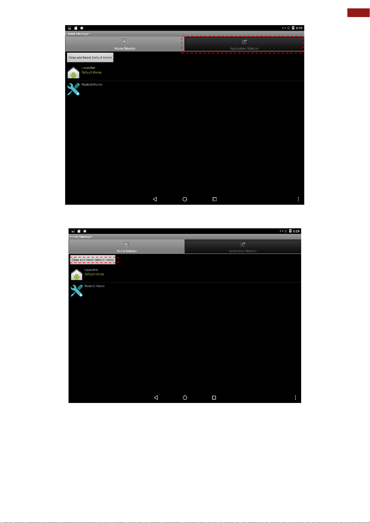
1. In the main APPS window, select the Home Manager APP and tap it to open.
2. Go to “Application Selector”, and choose the app which you want to run up automatically
after booting.
Page 33
33
Chapter 4: Operating the Device
3. Go back to “Home Selector” and press “Clear and Reset Default Home”.
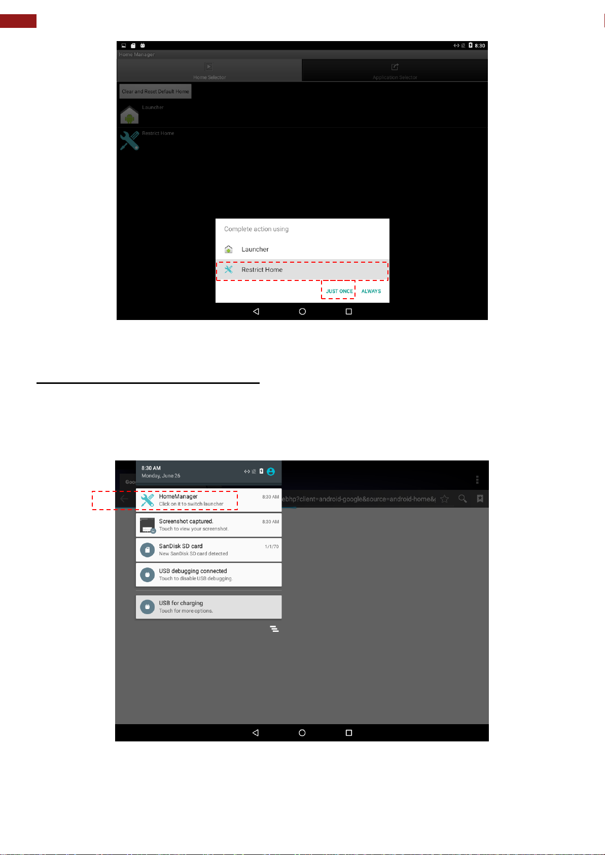
4. Select “Restrict Home” and “Always”, and then restart the computer to enable these settings.
Page 34
34
7~15" S-Series HMI Quick Start Guide
The system will automatically start the application which you selected and lock it. Any time user
presses home key or back key; the system will go back to the same application which you have
selected.
4.4.2 How to Unlock Applications
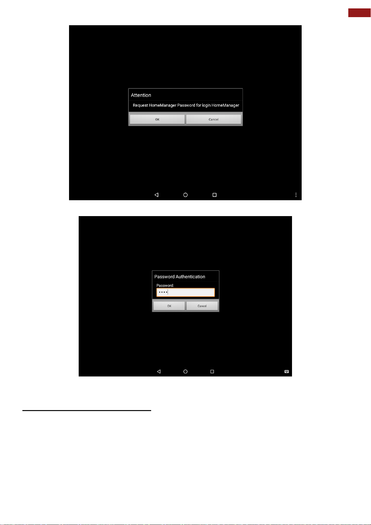
Follow the instruction below to reset Home Manager.
1. If you want to reset the home manager, pull down the left side to open the status bar and open
HomeManager.
2. System will request the password to login. Touch OK.
Page 35
35
Chapter 4: Operating the Device
Default password is “0000”.
3. Restart the system and you will go back to the normal Launcher.
4.4.3 How to Change Password
To change the password:
1. Go to Password Manager and set your own password for this APP.
2. The default password is “0000”. Enter a new password in New Password field, and then
tap Change Password.
Page 36
36
7~15" S-Series HMI Quick Start Guide
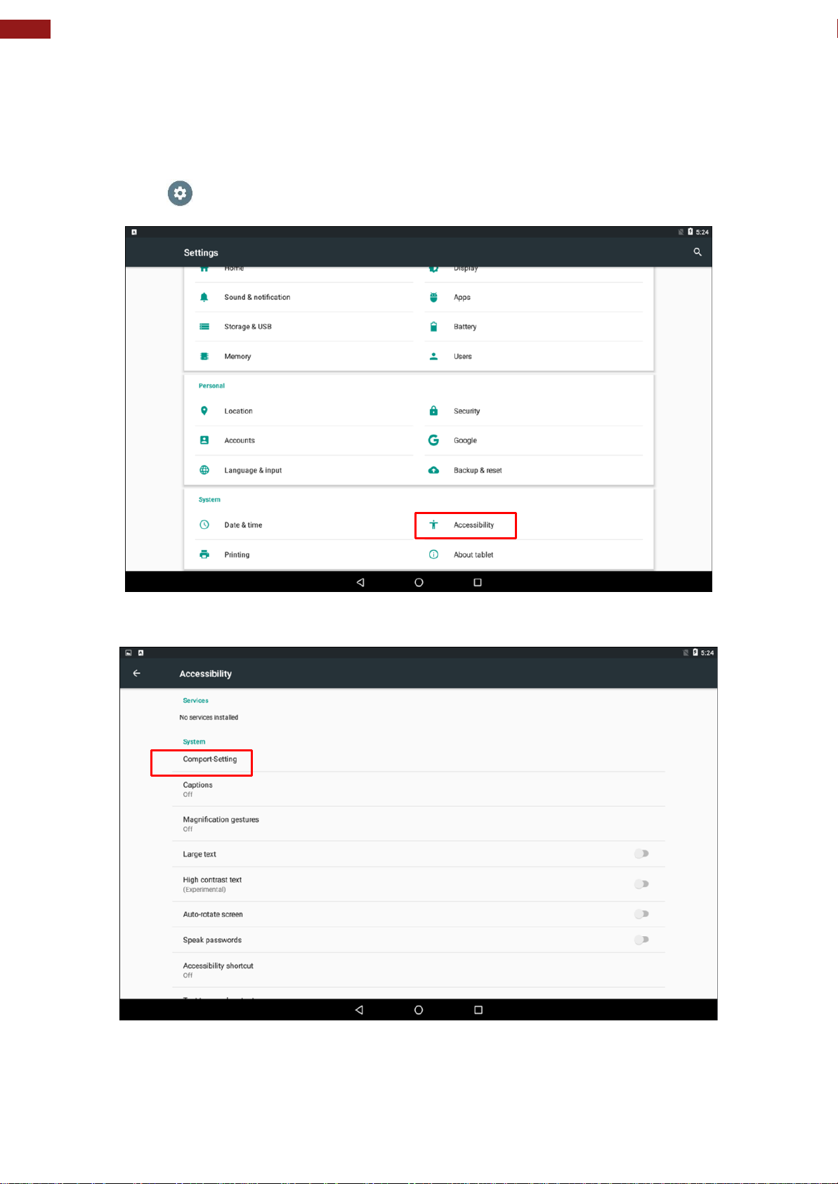
4.5 Configuring Serial Port Setting
Serial port setting can be configured for RS-232, RS-422 or RS-485. Winmate provide serial port
settings application for Android OS.
To configure serial port settings:
1. Settings > Accessibility.
2. Accessibility > System: Comport-Setting.
Page 37
37
Chapter 4: Operating the Device
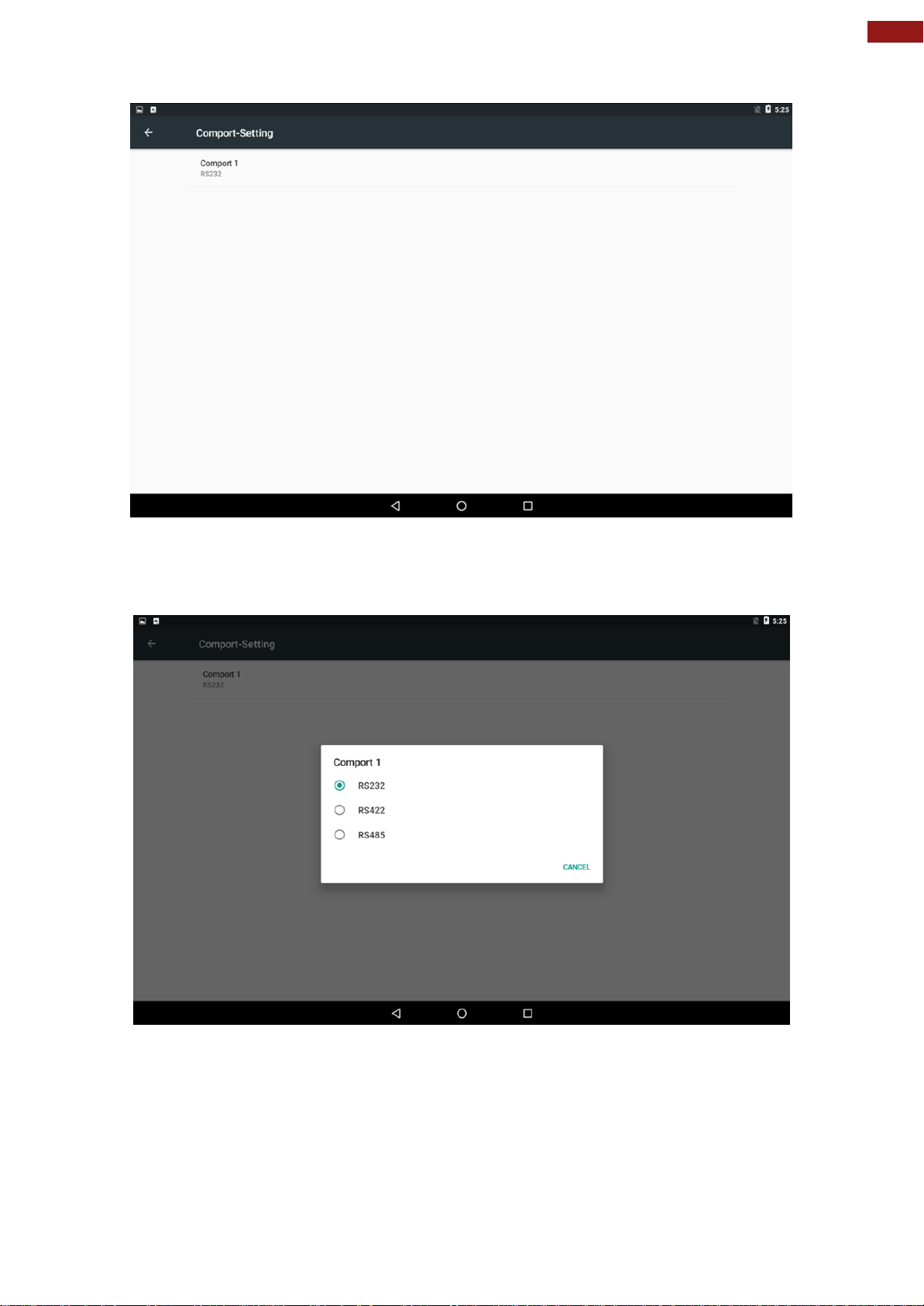
3. Comport-Setting > Comport 1/ Comport 2/ Comport 3
* Select Comport 1/ Comport 2/ Comport 3 that you want to configure.
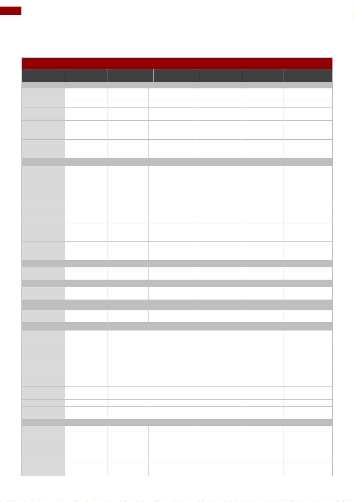
4. Comport 1 > RS232/RS422/RS485
* Configure Comport 1 settings
Page 38
38
7~15" S-Series HMI Quick Start Guide
Model Name
W07FA3SPCO1-POE
W07FA3SPCO1AC-POE
W10FA3SPCH2-POE
W10FA3SPCH2AC-PoE
W10FA3SPCH2LB
R15FA3S-PCC3PoE
Display
Size/ Type
7" TFT (Wide)
7" TFT (Wide)
10.1" TFT (Wide)
10.1" TFT
(Wide)
10.1" TFT
(Wide)
15"
Resolution
1024 x 600
1024 x 600
1280 x 800
1280 x 800
1280 x 800
1024 x 768
Brightness
1000 nit
1000 nit
350 nit
350 nit
350 nit
250 nit
Contrast Ratio
500:1 (typ.)
500:1 (typ.)
800:1 (typ.)
800:1 (typ.)
800:1 (typ.)
700:1 (typ.)
Viewing Angle
-75~75(H);75~70(V)
-75~75(H);75~70(V)
-85~85(H);
-85~85(V)
-85~85(H);85~85(V)
-85~85(H);85~85(V)
-80~80(H);70~70(V)
Max Colors
16.7M
16.7M
16.7M
16.7M
16.7M
16.7M
Touch
PCAP
PCAP
PCAP, AG
Coating
(Optional)
PCAP, AG
Coating
(Optional)
PCAP, AG
Coating
(Optional)
PCAP, AG
Coating(Optional)
System Specifications
Processor
Freescale®
Cortex® A9
i.MX6 Dual
Core 1GHz
(Optional
Quad Core)
Freescale®
Cortex® A9
i.MX6 Dual
Core 1GHz
(Optional
Quad Core)
Freescale®
Cortex® A9
i.MX6 Dual Core
1GHz
(Optional Quad
Core)
Freescale®
Cortex® A9
i.MX6 Dual
Core 1GHz
(Optional Quad
Core)
Freescale®
Cortex® A9
i.MX6 Dual
Core 1GHz
(Optional
Quad Core)
Freescale®
Cortex® A9 i.MX6
Dual Core 1GHz
(Optional Quad
Core)
Memory
1 GB LPDDR3
(Optional 2
GB)
1 GB LPDDR3
(Optional 2
GB
1 GB LPDDR3
(Optional 2 GB
1 GB LPDDR3
(Optional 2 GB
1 GB LPDDR3
(Optional 2 GB
1 GB LPDDR3
(Optional 2 GB
Storage
16 GB eMMC
(default), Micro
SD card
16 GB eMMC
(default),
Micro SD card
16 GB eMMC
(default), Micro
SD card
16 GB eMMC
(default), Micro
SD card
16 GB eMMC
(default),
Micro SD card
16 GB eMMC
(default), Micro
SD card
OS
Android 6.0
(Default),
Ubuntu 16.04
Android 6.0
(Default),
Ubuntu 16.04
Android 6.0
(Default),
Ubuntu 16.04
Android 6.0
(Default),
Ubuntu 16.04
Android 6.0
(Default),
Ubuntu 16.04
Android 6.0
(Default),
Ubuntu 16.04
Audio
Speaker
1 x 1 Watt
Speaker
1 x 1 Watt
Speaker
1 x 1 Watt
Speaker
1 x 1 Watt
Speaker
1 x 1 Watt
Speaker
1 x 1 Watt
Speaker
User Controls
LED Light Bar
N/A
RGB Light Bar
N/A
RGB Light Bar
All-Around
RGB Light Bar
N/A
Camera
Front Camera
2MP
(Optional)
2MP
(Optional)
2MP (Optional)
2MP (Optional)
N/A
2MP (Optional)
Input / Output Connectors
Power
2 Pin
Terminal Block
2 Pin
Terminal Block
2 Pin
Terminal Block
2 Pin
Terminal Block
2 Pin
Terminal Block
2 Pin
Terminal Block
Ethernet
1 x RJ 4510/100/1000
Mbps, LAN
support PoE
1 x RJ 4510/100/1000
Mbps, LAN
support PoE
1 x RJ 4510/100/1000
Mbps, LAN
support PoE
1 x RJ 4510/100/1000
Mbps, LAN
support PoE
1 x RJ 4510/100/1000
Mbps, LAN
support PoE
1 x RJ 4510/100/1000
Mbps, LAN
support PoE
USB Port
1 x USB 2.0
host, 1 x USB
OTG
1 x USB 2.0
host, 1 x USB
OTG
1 x USB 2.0
host, 1 x USB
OTG
1 x USB 2.0
host, 1 x USB
OTG
1 x USB 2.0
host, 1 x USB
OTG
1 x USB 2.0 host,
1 x USB OTG
Serial Port
1 x RS232/422/485
1 x RS232/422/485
1 x RS232/422/485
1 x RS232/422/485
1 x RS232/422/485
1 x RS232/422/485
CANBus
1 x CANBus
1 x CANBus
1 x CANBus
1 x CANBus
1 x CANBus
1 x CANBus
SD Card Slot
1 x Micro SD
Card Slot
1 x Micro SD
Card Slot
1 x Micro SD
Card Slot
1 x Micro SD
Card Slot
1 x Micro SD
Card Slot
1 x Micro SD
Card Slot
Power Specifications
Power Input
9~24V DC
9~24V DC
12V DC
12V DC
12V DC
12V DC
PoE
Power Device:
IEEE 802.3at
(25 W), IEEE
802.3af (15 W)
Power Device:
IEEE 802.3at
(25 W), IEEE
802.3af (15
W)
Power Device:
IEEE 802.3at
(25 W), IEEE
802.3af (15 W)
Power Device:
IEEE 802.3at
(25 W), IEEE
802.3af (15 W)
Power Device:
IEEE 802.3at
(25 W), IEEE
802.3af (15 W)
Power Device:
IEEE 802.3at
(25 W), IEEE
802.3af (15 W)
Power
Consumption
10 W
10 W
12 W
12 W
12 W
19W
Appendix
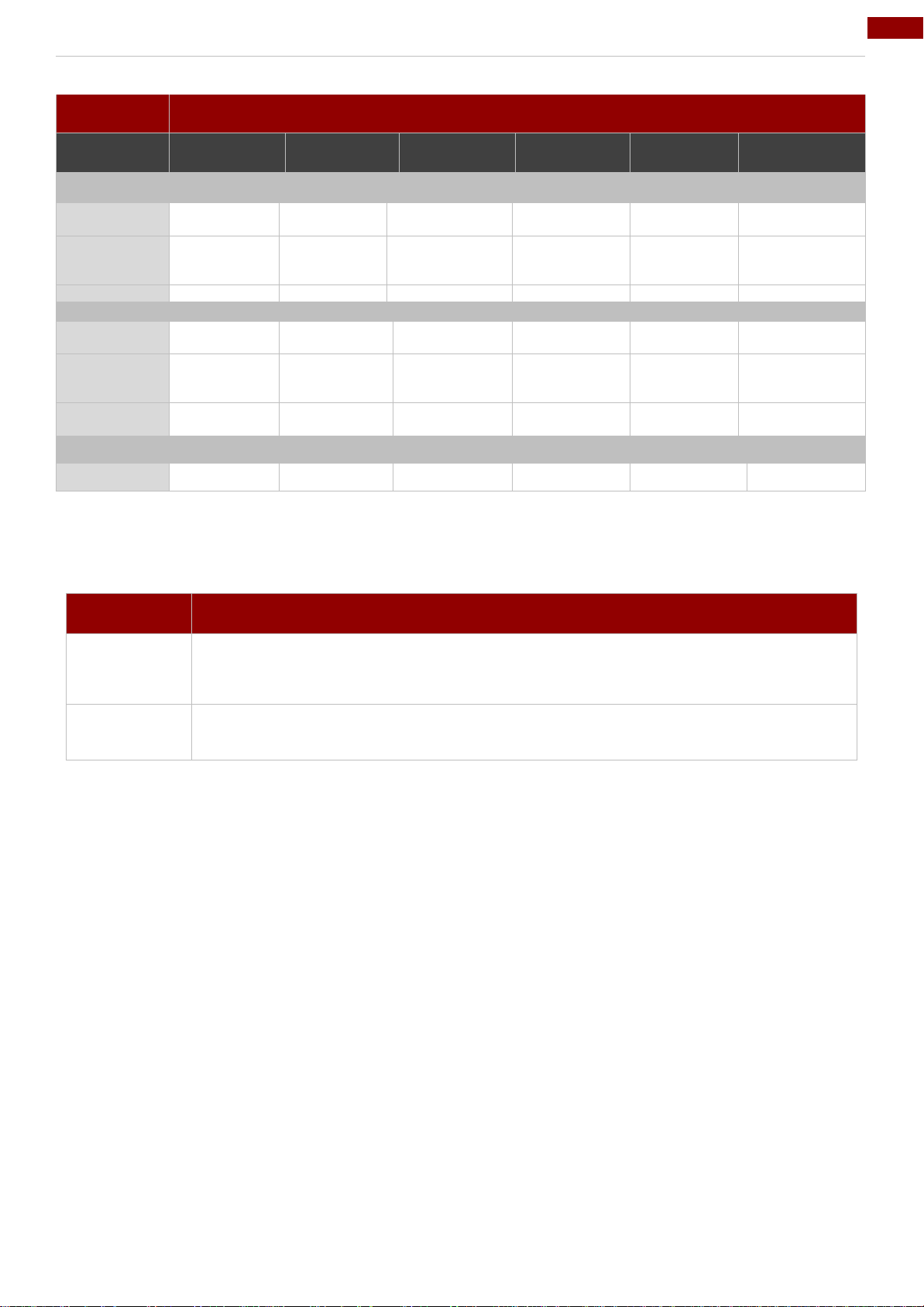
Appendix A: Product Specifications
Page 39
39
Appendix
Model Name
W07RK3SPCO1-POE
W07RK3SPCO1AC-POE
W10RK3SPCH2-POE
W10RK3SPCH2AC-POE
W10FA3SPCH2LB
R15RK3SPCC3-POE
Mechanical Specifications
Dimensions
189.4 x 145.4
x 36.1 mm
189.4 x 145.4
x 36.1 mm
263.28 x 171 x
35.7 mm
263.28 x 171 x
35.7 mm
263.28 x 171 x
35.7 mm
363.40 x 277.86
x 44.50 mm
Mounting
Panel mount,
VESA 75x75
Panel mount,
VESA 75x 75
Panel mount,
VESA 75x75,
Front Mount
Panel mount,
VESA 75x75,
Front Mount
Panel mount,
VESA 75x75,
Front Mount
Panel mount,
VESA 100x100
Cooling
Fanless
Fanless
Fanless
Fanless
Fanless
Fanless
Environment Considerations
Operating
Temp.
0 °C to 50 °C
0 °C to 50 °C
0 °C to 50 °C
0 °C to 50 °C
0 °C to 50 °C
0 °C to 50 °C
Humidity
10% to 90%
(noncondensing)
10% to 90%
(noncondensing
10% to 90%
(noncondensing
10% to 90%
(noncondensing
10% to 90%
(noncondensing
10% to 90%
(non-condensing
IP Rating
Front: IP65,
Full: IP22
Front: IP65,
Full: IP22
Front: IP65,
Full: IP22
Front: IP65,
Full: IP22
Front: IP65,
Full: IP22
Front: IP65,
Full: IP22
Certification
Safety
CE, FCC
CE, FCC
CE, FCC
CE, FCC
CE, FCC
CE, FCC
HF RFID
Standard
Purpose
ISO-14443 A
Standard for MIFARE technology, which used in smart cards and proximity cards
ISO-15693
Standard for tracking items
Appendix B: HF RFID Reader Specifications
The HF RFID Reader of this device supports the following card type.
Page 40

Winmate Inc.
9F, No.111-6, Shing-De Rd., San-Chung District,
New Taipei City 24158, Taiwan, R.O.C
www.winmate.com
Copyright © Winmate Inc. All rights reserved.
 Loading...