

Page 1

OMIW - OPS PC Module
Intel® Broadwell Core i5-5200U 2.2GHz Processor, two USB3.0, Display Port,
two audio jacks for microphone, line-in and line-out, optional Wi-Fi/3G.
Optional Pluggable Specification (OPS) enables easy integration of a digital
signage computing system or a pluggable module into the display panel.
User Manual
Version 1.0
Document Part Number: 915211171009
Page 2

OMIW- OPS PC Module
II
Preface
Copyright Notice
No part of this document may be reproduced, copied, translated, or transmitted in any
form or by any means, electronic or mechanical, for any purpose, without the prior
written permission of the original manufacturer.
Trademark Acknowledgement
Brand and product names are trademarks or registered trademarks of their respective
owners.
Disclaimer
We reserve the right to make changes, without notice, to any product, including circuits
and/or software described or contained in this manual in order to improve design and/or
performance. We assume no responsibility or liability for the use of the described
product(s), conveys no license or title under any patent, copyright, or masks work rights
to these products, and makes no representations or warranties that these products are
free from patent, copyright, or mask work right infringement, unless otherwise specified.
Applications that are described in this manual are for illustration purposes only. We
make no representation or warranty that such application will be suitable for the
specified use without further testing or modification.
Warranty
We warrant that each of its products will be free from material and workmanship defects
for a period of one year from the invoice date.(Standard is one year, extended warranty
will need to discuss with our sales representatives. If the customer discovers a defect, we
will, at its option, repair or replace the defective product at no charge to the customer,
provided it is returned during the warranty period of one year, with transportation
charges prepaid. The returned product must be properly packaged in its original
packaging to obtain warranty service.
If the serial number and the product shipping data differ by over 30 days, the
in-warranty service will be made according to the shipping date. In the serial numbers
the third and fourth two digits give the year of manufacture, and the fifth digit means
the month (e. g., with A for October, B for November and C for December).
For example, the serial number 1W16Axxxxxxxx means October of year 2016.
Page 3

OMIW- OPS PC Module
III
Packing List
Before using this product, please make sure that all the items listed below are present in
your package:
OMIW - OPS Module
User Manual & Driver CD
If any of these items are missing or damaged, contact your distributor or sales
representative immediately.
Customer Service
We provide a service guide as below for any problem by the following steps: First, contact
your distributor, sales representative, or our customer service center for technical support if
you need additional assistance. You need to prepare the following information before you
call:
Product serial number
Peripheral attachments
Software (OS, version, application software, etc.)
Detailed problem description
The exact wording of any error messages
In addition, free technical support is available from our engineers every business day. We are
always ready to give advice on application requirements or specific information on the
installation and operation of any of our products. Please do not hesitate to call or e-mail us.
Page 4
OMIW- OPS PC Module
IV
Advisory Conventions
NOTE:
A note is used to emphasize helpful information
IMPORTANT:
An important note indicates information that is important for you to know.
CAUTION
A Caution alert indicates potential damage to hardware and explains how to
avoid the potential problem.
WARNING!
An Electrical Shock Warning indicates the potential harm from electrical
hazards and how to avoid the potential problem.
WARNING!
Always completely disconnect the power from OPS module whenever
you work with the hardware. Do not make connections while the
power is on. Sensitive electronic components can be damaged by
sudden power surges.
Four types of advisories are used throughout the user manual to provide helpful
information or to alert you to the potential for hardware damage or personal injury.
These are Notes, Important, Cautions, and Warnings. The following is an example of each
type of advisory.
Safety Precautions
Page 5

OMIW- OPS PC Module
V
CAUTION
Always ground yourself to remove any static charge before touching
the CPU card. Modern electronic devices are very sensitive to static
electric charges. As a safety precaution, use a grounding wrist strap at
all times. Place all electronic components in a static-dissipative surface
or static-shielded bag when they are not in the chassis.
Version
Date
Note
Author
1.0
9-Aug-2016
Initial document release
Austin Chang
Safety and Warranty
1. Please read these safety instructions carefully.
2. Please keep this user manual for later reference.
3. Please disconnect this equipment from any AC outlet before cleaning. Do not use
liquid or spray detergents for cleaning. Use a damp cloth.
4. For pluggable equipment, the power outlet must be installed near the equipment
and must be easily accessible.
5. Keep this equipment away from humidity.
6. Put this equipment on a reliable surface during installation. Dropping it or letting it
fall could cause damage.
7. Make sure the voltage of the power source is correct before connecting the
equipment to the power outlet.
8. Position the power cord so that people cannot step on it. Do not place anything
over the power cord.
9. All cautions and warnings on the equipment should be noted.
10. If the equipment is not used for a long time, disconnect it from the power source to
avoid damage by transient over-voltage.
11. If any of the following situations arises, get the equipment checked by service
personnel:
A. The power cord or plug is damaged.
B. Liquid has penetrated into the equipment.
C. The equipment has been exposed to moisture.
D. The equipment does not work well, or you cannot get it to work according to
the user’s manual.
E. The equipment has been dropped and damaged.
F. The equipment has obvious signs of breakage.
Revision History
Page 6

OMIW- OPS PC Module
VI
Contents
CHAPTER 1 GENERAL INFORMATION ......................................................................................................... 1
1.1 INTRODUCTION .......................................................................................................................................... 1
1.2 FEATURES ................................................................................................................................................. 1
1.3 PRODUCT SPECIFICATIONS............................................................................................................................ 2
1.3.1 Hardware Specifications ............................................................................................................... 2
1.3.2 Software Support .......................................................................................................................... 3
1.4 PHYSICAL DESCRIPTION ............................................................................................................................... 4
1.4.1 I/O Placement ............................................................................................................................... 4
1.4.2 Dimensions .................................................................................................................................... 5
CHAPTER 2 HARDWARE INSTALLATION ..................................................................................................... 7
2.1 CONNECTORS ............................................................................................................................................ 7
2.1.1 Display Port 1.2 Connector ............................................................................................................ 8
2.1.2 USB 3.0 Connector ......................................................................................................................... 8
2.1.3 Audio Connector ............................................................................................................................ 8
2.1.4 Ethernet RJ45 Connector ............................................................................................................... 9
2.1.5 Power Button................................................................................................................................. 9
2.1.6 Reset Button .................................................................................................................................. 9
2.1.7 OPS Connector ............................................................................................................................... 9
2.2 HARDWARE INSTALLATION ......................................................................................................................... 11
2.2.1 HDD/SSD Installation .................................................................................................................. 11
2.2.2 SIM Card Installation ................................................................................................................... 12
2.2.3 External Antenna Installation ...................................................................................................... 13
2.2.4 Other Internal Parts..................................................................................................................... 13
2.3 PLUGGABLE MODULE INSTALLATION ............................................................................................................ 15
CHAPTER 3 AMI BIOS SETUP ................................................................................................................... 17
3.1 HOW AND WHEN TO USE BIOS SETUP ........................................................................................................ 17
3.2 BIOS FUNCTIONS .................................................................................................................................... 18
3.2.1 Main Menu .................................................................................................................................. 18
3.2.2 Advanced Settings ....................................................................................................................... 20
3.2.3 Chipset Menu .............................................................................................................................. 39
3.2.4 Boot Menu................................................................................................................................... 41
3.2.5 Security Menu ............................................................................................................................. 42
3.2.6 Save & Exit .................................................................................................................................. 43
Page 7

OMIW- OPS PC Module
VII
3.3 USING RECOVERY WIZARD TO RESTORE COMPUTER ........................................................................................ 45
CHAPTER 4 DRIVER INSTALLATION .......................................................................................................... 48
4.1 CHIPSET DRIVER ...................................................................................................................................... 48
4.2 GRAPHICS DRIVER .................................................................................................................................... 51
4.3 AUDIO DRIVER ........................................................................................................................................ 54
4.4 ETHERNET DRIVER .................................................................................................................................... 56
4.5 INTEL® MANAGEMENT ENGINE SOFTWARE ............................................................................................... 59
4.6 USB 3.0 DRIVER INSTALLATION (WINDOWS 7) .............................................................................................. 62
CHAPTER 5 TECHNICAL SUPPORT ............................................................................................................ 73
5.1 SOFTWARE DEVELOPER SUPPORT ................................................................................................................ 73
5.1.1 Winmate Download Center ......................................................................................................... 73
5.1.2 Winmate File Share ..................................................................................................................... 73
Page 8

OMIW- OPS PC Module
1
General Information
This chapter includes OMIW - OPS PC Module
background information.
Page 9

User Manual Chapter 1 General Information
OMIW- OPS PC Module
1
Chapter 1 General Information
This chapter includes Winmate® OMIW - OPS PC Module background information such
as features, hardware specification, dimensions and appearance.
1.1 Introduction
Thank you for choosing the Winmate® OMIW - OPS PC Module. Optional Pluggable
Specification (OPS) enables easy integration of a digital signage computing system or a
pluggable module into the display panel. The module is powered by Intel® Broadwell
Core i5-5200U 2.2 GHz processor that allows running on Window based operating
system.
OPS module that can be installed into the display panel through a single and standard
interfacing based on the 80-pin JAE plug and receptacle connectors. The power supply to
the motherboard together with the defined feature interfaces are being routed through
the set of connectors, and provide a functional system level computing solution for
digital signage.
There is an advanced full set of I/O ports including one display port, two USB 3.0
connectors, and two audio jacks for line-in and line-out. The current model allows adding
Wi-Fi or 3G models for better connectivity and information exchange.
1.2 Features
Winmate® OMIW - OPS Module has the following features:
Intel® Broadwell Core i5-5200U 2.2GHz processor
DDR3L 4GB system memory
Removable 2.5" SATA Drive Bay
Wi-Fi / 3G modules (optional)
Page 10

User Manual Chapter 1 General Information
OMIW- OPS PC Module
2
Model Name
OMIW – OPS PC Module
System
Specifications
CPU
Intel® Broadwell Core i5-5200U
BIOS
AMI System BIOS
System Chipset
SoC Integrated
System Memory
SO-DIMM DDR3L-1600, up tp 8GB (Default 4GB)
Storage
Removable 2.5 SATA Drive Bay (Default 2.5" HDD 500G)
Graphic Chipset
Intel® HD Graphic 5500
Ethernet
Intel Gigabit-LAN DHY I218
Audio
Realtek ALC 283 codec
I/O Interface
Front I/O
1 x RJ-45 Giga GbE
2 x USB 3.0
1 x Display Port 1.2
2 x Audio phone jack (Line-in/ Line-out)
1 x Power button
1 x Reset button
Rear (OPS
Interconnector)
1 x JAE 80-Pin connector (follow OPS Standard)
Internal I/O
1 x Sim card slot
1 x Mini-PCIe (for wireless module or 3G Module)
Power
Requirements
Power Consumption
25W (Burn-in Test)
Input Voltage
12V~19V DC in (via OPS interconnection)
Physical
Characteristics
Dimensions
(W x H x D)
200 x 30 x 118mm (OPS compliant)
Weight
1.5kg (3.3lb)
Environment
Operating
Temperature
0°C~+50°C
Storage
Temperature
-20°C~+60°C ( -4~1400F )
Operating Humidity
10%~ 95% (non-condensing, RH)
Certification
Electromagnetic
CE, FCC
Wireless
Communications
Wi-Fi
Mini PCIe Wi-Fi Module (Optional)
3G
Mini PCle 3G Module (Optional)
1.3 Product Specifications
1.3.1 Hardware Specifications
Page 11

User Manual Chapter 1 General Information
OMIW- OPS PC Module
3
Item
Driver
Windows 7
Windows 8
Windows 10
1
Chipset Driver
☑
☑
☑
2
Graphics Driver
☑
☑
☑
3
Audio Driver
☑
☑
☑
4
Ethernet Driver
☑
☒
☒
5
Intel Management Engine
Software
☑
☑
☑
6
USB 3.0 Driver
☑
☒
☒
1.3.2 Software Support
The following drivers are available for the OMIW-OPS PC Module.
Page 12

User Manual Chapter 1 General Information
OMIW- OPS PC Module
4
①
Removable HDD/SSD
⑥
RJ45 Giga GbE
②
Line Out
⑦
2 x USB 3.0
③
Line In
⑧
Display Port 1.2
④
Reset Button
⑨
Antenna (Optional)
⑤
Power Button
1.4 Physical Description
This section explains physical characteristics of OMIW-OPS PC Module.
1.4.1 I/O Placement
The module front panel consists of optional antenna slots, power/reset buttons,
audio jacks, RJ45 connector, a DSP port, and two USB ports.
Front View
Rear View
Page 13
User Manual Chapter 1 General Information
OMIW- OPS PC Module
5
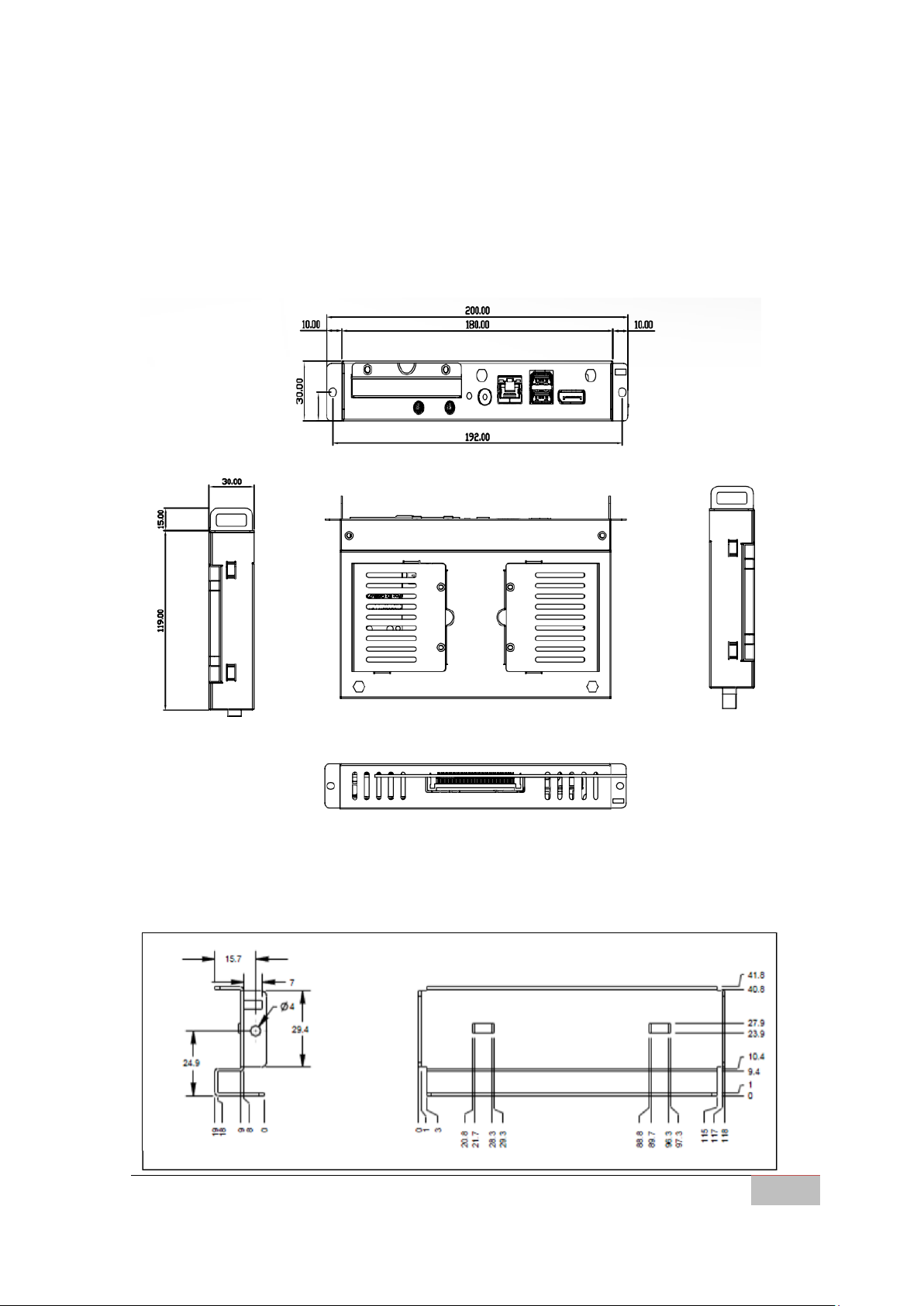
1.4.2 Dimensions
Figure below shows the dimensions of the Pluggable Module. The overall dimension
of the module including the mounting frame is 119mm x 30mm x 200 mm.
OMIW-OPS PC Module Dimensions
119 x 30 x 200 (unit: mm)
The sides of the module consist of four guide holes which, when come into contact
with the locking pins on the guide rail, lock the module during docking/undocking.
Dimensions of the Guide Rail
Page 14

OMIW- OPS PC Module
6
Hardware Specifications
This chapter provides information on how to use
jumpers and connectors on the motherboard, and
OMIW - OPS PC Module hardware installation
instruction.
Page 15

User Manual Chapter 2 Hardware Installation
OMIW- OPS PC Module
7
Chapter 2 Hardware Installation
This chapter provides information on the connectors located on the motherboard
and hardware installation instruction.
2.1 Connectors
Connectors connect this board with other parts of the system. The table below shows
all connectors on the OMIW – OPS PC Module.
Front Side
Rear Side
Page 16
User Manual Chapter 2 Hardware Installation
OMIW- OPS PC Module
8
Pin №
Symbol
Pin №
Symbol
1
Lane 0 +
2
GND
3
Lane 0 -
4
Lane 1 +
5
GND
6
Lane 1 -
7
Lane 2 +
8
GND
9
Lane 2 -
10
Lane 3 +
11
GND
12
Lane 3 -
13
AUX_EN
14
GND
15
AUX +
16
GND
17
AUX -
18
Hot Plug
19
GND
20
DP_PWR
Pin №
Name
Pin №
Name
1
+5V
2
USB_D-
3
USB_D+
4
GND
5
STDA_SSRX-
6
STDA_SSRX+
7
GND_DRAIN
8
STDA_SSTX-
9
STDA_SSTX+
10
+5V
11
USB_D-
12
USB_D+
13
GND
14
STDA_SSRX-
15
STDA_SSRX+
16
GND
17
STDA_SSTX-
18
STDA_SSTX+
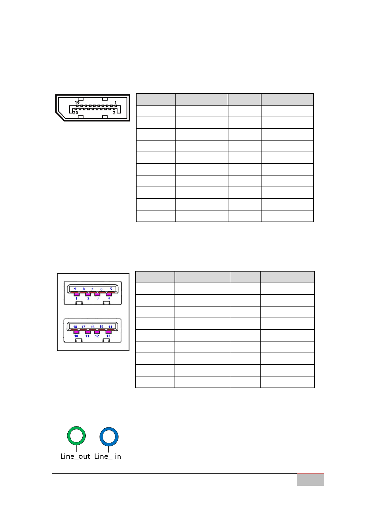
2.1.1 Display Port 1.2 Connector
Use Display Port 1.2 to connect a video source to a display device such as a computer
monitor.
2.1.2 USB 3.0 Connector
OMIW – OPS PC Module provides two USB 3.0 connectors.
2.1.3 Audio Connector
OMIW – OPS PC Module offers stereo audio ports by two 3.5 ear phone jack connectors of
Line_ out and Line_ in.
Page 17
User Manual Chapter 2 Hardware Installation
OMIW- OPS PC Module
9
Pin №
Signal Name
1
Transfer Data+
2
Transfer Data-
3
Receive Data+
4
Bi-directional Data+
5
Bi-directional Data-
6
Receive Data-
7
Bi-directional Data+
8
Bi-directional Data-
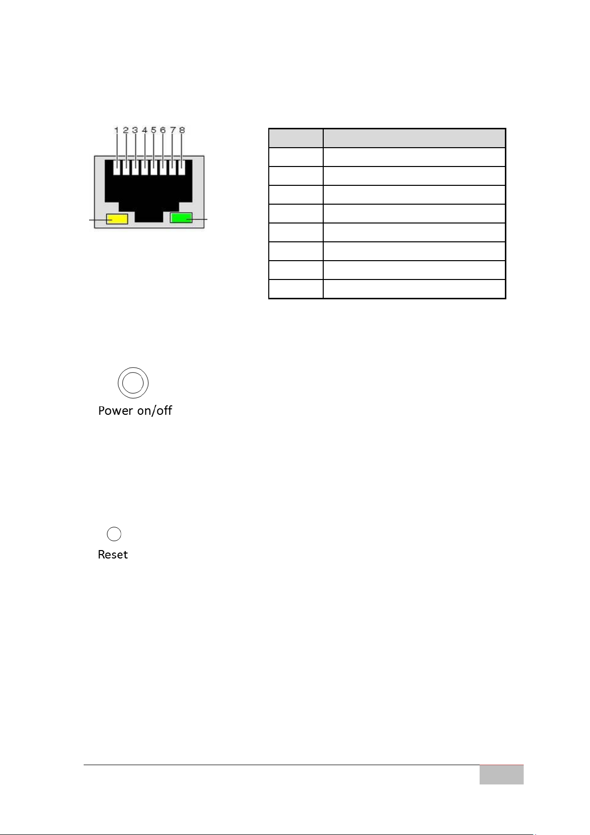
2.1.4 Ethernet RJ45 Connector
The Ethernet port uses a standard RJ-45 jack connector with LED indicators on the
front side to show Active/Link status and Speed status.
2.1.5 Power Button
OMIW – OPS PC Module comes with a Power On/ Off button on the front side.
2.1.6 Reset Button
OMIW – OPS PC Module comes with a Reset button. If user needs to reset the device,
user needs to use thin object to press reset button.
2.1.7 OPS Connector
OMIW uses JAE 80-pin connector to connect to the display board. The connectors
have a total of 80 pins, supporting power and signal lines.
Page 18

User Manual Chapter 2 Hardware Installation
OMIW- OPS PC Module
10
Pin № Name
Pin № Name
Pin № Name
Pin № Name
1
DDP_3N
2
DDP_3P
3
GND
4
DDP_2N
5
DDP_2P
6
GND
7
DDP_1N
8
DDP_1P
9
GND
10
DDP_0N
11
DDP_0P
12
GND
13
DDP_AUXN
14
DDP_AUXP
15
DDP_HPD
16
GND
17
TMDS_CLK-
18
TMDS_CLK+
19
GND
20
TMDS0
21
TMDS0+
22
GND
23
TMDS1-
24
TMDS1+
25
GND
26
TMDS2-
27
TMDS2+
28
GND
29
H_DAT_OUT
30
H_CLK_OUT
31
HP_DET_OUT
32
GND
33
DC_IN
34
DC_IN
35
DC_IN
36
DC_IN
37
DC_IN
38
DC_IN
39
DC_IN
40
DC_IN
41
RSVD
42
RSVD
43
RSVD
44
RSVD
45
RSVD
46
RSVD
47
RSVD
48
RSVD
49
RSVD
50
CB_SYS_FAN
51
COM_RXD
52
COM_TXD
53
GND
54
StdA_SSRX
55
StdA_SSRX+
56
GND
57
StdA_SSTX-
58
StdA_SSTX+
59
GND
60
USB_PN2
61
USB_PP2
62
GND
63
USB_PN1
64
USB_PP1
65
GND
66
USB_PN0
67
USB_PP0
68
GND
69
REAR_L
70
REAR_R
71
HDMI_CEC_OUT
72
PB_DET
73
PS_ON#
74
PWR_STATUS
75
GND
76
GND
77
GND
78
GND
79
GND
80
GND
Page 19

User Manual Chapter 2 Hardware Installation
OMIW- OPS PC Module
11
WARNING!
Switch off the power and unplug the power cord. Each time the OPS
Module is serviced, users should be aware of this condition.
2.2 Hardware Installation
This section explains how to replace HDD/SDD, install SIM card and external
antennas, and access other internal parts of the OMIW-OPS PC Module.
2.2.1 HDD/SSD Installation
Follow the procedure below to install SIM Card:
1. Disconnect OPS module from the power source.
2. Loosen two Phillips M3x4 flathead black screws on the I/O side.
3. Open the cover door.
4. Carefully pull out the 2.5”hard disk bay.
Page 20

User Manual Chapter 2 Hardware Installation
OMIW- OPS PC Module
12
5. Exchange with the new hard disk. Be sure to check the orientation of the
hard disk is correct.
6. When finished, insert the cover door back and carefully tighten two Phillips
M3x4 flathead black screws.
2.2.2 SIM Card Installation
Follow the procedure below to install SIM Card:
1. Disconnect OPS module from the power source.
2. Loosen two Phillips M3x4 flathead black screws on the rear side.
3. Pull the cover lid up.
4. Carefully insert the SIM card to the SIM card slot. Be sure to check the
orientation of the SIM-card is correct.
7. When finished, insert the cover door back and carefully tighten two Phillips
M3x4 flathead black screws.
Page 21

User Manual Chapter 2 Hardware Installation
OMIW- OPS PC Module
13
IMPORTANT:
Both antennas should be installed.
2.2.3 External Antenna Installation
Follow the procedure below to install external antennas:
1. Mechanically fix the antenna to the holder and tighten the antenna stylus.
2. Adjust the antenna angle for better signal.
2.2.4 Other Internal Parts
Follow the procedure below to access other internal parts of the OMIW-OPS PC
Module:
1. Disconnect OPS module from the power source.
2. Loosen the four Phillips M3 x 5 truss head silver screws on the top cover.
Page 22

User Manual Chapter 2 Hardware Installation
OMIW- OPS PC Module
14
3. Remove the top cover.
4. Make all necessary modifications.
5. When finished, insert the cover door back and carefully tighten four Phillips M3
x 5 truss head silver screws.
Page 23

User Manual Chapter 2 Hardware Installation
OMIW- OPS PC Module
15
CAUTION
When plugging OPS PC module into an OPS display, make sure the
module’s heat sink is facing outside of the display.
NOTE:
Please contact Winmate to check the availability of OPS display.
2.3 Pluggable Module Installation
To install OMIW-OPS PC Module to the display:
1. Insert the box into the display.
2. Fasten two screws as illustrated.
OPS PC Box Installation
Page 24

OMIW- OPS PC Module
16
AMI BIOS Setup
This chapter contains BIOS Configuration and OS
Recovery information for OMIW motherboard.
Page 25

User Manual Chapter 3 AMI BIOS Setup
OMIW- OPS PC Module
17
IMPORTANT:
Updated BIOS version may be published after the manual released.
Check the latest version of BIOS on the website.
Key
Function
Del
Enters the BIOS setup menu.
F7
Display the boot menu. Lists all bootable devices that are connected to the
system. With cursor ↑and cursor ↓and by pressing <ENTER>, select the
device used for the boot.
Pause
Pressing this key stops the POST. Press any other key to resume the POST.
Key
Function
F1
General Help
F2
Previous Values
F3
Optimized Defaults
F4
Save & Exit
Esc
Exit
+/-
Change Opt.
Enter
Select or execute command
Cursor ↑
Moves to the previous item
Cursor ↓
Goes to the next item
Cursor ←
Moves to the previous item
Cursor →
Goes to the next item
Chapter 3 AMI BIOS SETUP
3.1 How and When to Use BIOS Setup
To enter the BIOS setup, you need to connect an external USB keyboard, press Del
key when the prompt appears on the screen during start up. The prompt screen
shows only few seconds so need press Del key quickly.
You may need to run BIOS setup utility for reasons listed below:
1. Error message on screen indicates to check BIOS setup
2. Restoring the factory default settings.
3. Modifying the specific hardware specifications
4. Necessity to optimize specifications
BIOS Navigation Keys
The following keys are enabled during POST:
The following Keys can be used after entering the BIOS Setup.
Page 26

User Manual Chapter 3 AMI BIOS Setup
OMIW- OPS PC Module
18
NOTE:
You can press the F1, F2, F3, F4, –/+, and Esc keys by connecting a
USB keyboard to your computer.
3.2 BIOS Functions
The OMIW motherboard has AMI BIOS built-in and a CMOS SETUP utility that allow
users to configure required settings or to activate certain system features. The
follwoing sections describe the configuration options found in the menu items.
3.2.1 Main Menu
The Main menu displays the basic information about yoursystem including BIOS
version, processor RC version, system language, time, and date.
When you enter BIOS setup, the first menu that appears on the screen is the main
menu.It contains the system information including BIOS version, processor RC version,
system language, time, and date.
Page 27

User Manual Chapter 3 AMI BIOS Setup
OMIW- OPS PC Module
19
BIOS
Setting
Description
Setting Option
Effect
System
Language
Displays the system
language. [English] is
set up by default.
Adjustment of the
language
Set the language in
other language. The
language in this
device is English.
System
Date/Time
This is current date
setting. The time is
maintained by the
battery when the
device is turned off.
Date and time
changes.
Set the date in the
format [mm/dd/yyyy];
The time in the
format:
[hh/mm/ss]
Access
Level
The current user
access settings
Changes to the level
of access
Administrator is set up
by the default
Page 28

User Manual Chapter 3 AMI BIOS Setup
OMIW- OPS PC Module
20
CAUTION
Handle advanced BIOS settings page with caution. Any changes can
affect the operation of your computer.
3.2.2 Advanced Settings
Select the Advanced Tab from the OMIW setup menu to enter the advanced BIOS
setup screen. You can select any of the items on the left frame of the screen to go to
the sub menu for the item, such as CPU Configuration. You can use the <Arrow> keys
enter all advanced BIOS setup options. The advanced BIOS setup menu is shown
below. The submenus described on the following pages.
Page 29

User Manual Chapter 3 AMI BIOS Setup
OMIW- OPS PC Module
21
BIOS Setting
Description
Setting
Option
Effect
CPU Configuration
Configures CPU settings
Enter
Opens submenu
Trusted Computing
Configures Trusted
Computing parameters
Enter
Opens submenu
ACPI Settings
Configures ACPI settings
Enter
Opens submenu
F81866 Super I/O
Configuration
Configures Super I/O settings
Enter
Opens submenu
Hardware Monitor
Configures H/W Monitor
settings
Enter
Opens submenu
S5 RTC Wake Settings
Configures RTC Wake
parameters
Enter
Opens submenu
SATA Configuration
Configures SATA parameters
Enter
Opens submenu
CSM Configuration
Configures CSM parameters
Enter
Opens submenu
USB Configuration
Configures USB parameters
Enter
Opens submenu
Intel ® Ethernet
Connection
Configures Network
Connection settings
Enter
Opens submenu
For items marked ► press <Enter> for more options.
Page 30

User Manual Chapter 3 AMI BIOS Setup
OMIW- OPS PC Module
22
3.2.2.1 CPU Configuration
CPU Configuration allows you to change CPU settings. Use key arrows to navigate
through the menu.
Page 31

User Manual Chapter 3 AMI BIOS Setup
OMIW- OPS PC Module
23
BIOS Setting
Description
Setting Option
Effect
Hyper-threading
Intel's proprietary
simultaneous
multithreading (SMT)
implementation used
to improve
parallelization of
computations (doing
multiple tasks at once)
Enable
*Enabled for
Windows XP and
Linux (OS
optimized for
Hyper-Threading
Technology)
Enables this
function
Disable
*Disabled for
other OS (OS not
optimized for
Hyper-Threading
Technology
When disabled only
one thread per
enabled core is
enabled
Execute Disable
Bit
Allows the processor
to classify areas in
memory where
application code can
or cannot execute and
reduce system
exposure to viruses
and malicious code.
Enabled
Prevents certain
classes of malisious
baffer overflow
attacks when
combined with a
supporting OS
Disabled
Disable this
function
Intel
Virtualization
Technology
Help accelerate virtual
machine applications.
Enabled/
Disabled
Enables or disables
this function
Boot
Performance
Mode
This feature selects the
performance state the
BIOS will set before
the OS hand-off.
Max Non-Turbo
Performance
Enables Max
Non-Turbo
Performance
Turbo
Performance
Enables Turbo
Performance
Page 32

Page 33

User Manual Chapter 3 AMI BIOS Setup
OMIW- OPS PC Module
25
EIST (Enhanced
Intel SpeedStep
Technology)
Aallows the system to
automaticallyadjust
processor voltage and
core frequency in an
effort to reduce power
consump-tion and
heat dissipation.
Enabled/
Disabled
Enables or disables
this function
Turbo Mode
This feature allows
processor cores to run
faster than the
frequency
recommendedby the
manufacturer.
Enabled/
Disabled
Enables or disables
this function
CPU C States
C-States architecture
can further reduce
power consumption
from the basic C1 (Halt
State) statethat blocks
clock cycles to the
CPU.
Enabled/
Disabled
Enables or disables
this function
CPU DTS
Determine which
temperature values
are used by ACPI
terminal management
Disabled
ACPI terminal
management uses
EC reported
temperature values
Enabled
ACPI terminal
management uses
DTS SMM
mechanism to
obtain temperature
CPU values.
Page 34

User Manual Chapter 3 AMI BIOS Setup
OMIW- OPS PC Module
26
BIOS Setting
Description
Setting Option
Effect
Security Device
Support
Enable or disable BIOS
support for security
device
Enabled/Disabled
Set required
configuration
TPM State
Enable or disable TPM
state.
Enabled/Disabled
Set required
configuration
Pending
Operation
Control the Security
Device.
None/TPM Clear
Schedule an
Operation for
the Security
Device.
Device Select
Select devices will be
enumerated.
Auto/TPM 1.2
/TPM 2.0
TPM 1.2 will
restrict
support to
TPM 1.2
devices, TPM
2.0 will
3.2.2.2 Trusted Computing
Page 35

User Manual Chapter 3 AMI BIOS Setup
OMIW- OPS PC Module
27
restrict
support to
TPM 2.0
devices ,Auto
will support
both with the
default set to
TPM 2.0
devices if not
found, TPM
1.2 devices
will be
enumerated
Page 36

User Manual Chapter 3 AMI BIOS Setup
OMIW- OPS PC Module
28
BIOS Setting
Description
Setting Option
Effect
Enable ACPI
Auto
Configuration
BIOS ACPI Auto
Configuration
Enable/ Disable
Enables or disables this
function
Enable
Hibernation
Control hibernation
Enable/ Disable
Enables or disables this
function
APCI Sleep State
This option allows
you to specify which
mode will be used
during the transition
to power-saving
state
S1 (Power
On-Suspend)
Removes power from
the hard drive, some
expansion cards, plus
extinguished monitor.
All other components
(processor, memory,
chipset) operate in
normal mode, only a
transition to a low
frequency.
3.2.2.3 ACPI Settings
Page 37

User Manual Chapter 3 AMI BIOS Setup
OMIW- OPS PC Module
29
S3 (Suspended
to RAM)
Before going into S3 all
the information about
the state of the various
components is stored in
the memory.
Lock Legacy
Resources
Prevents the OS
from changing
resources to serial,
parallel, or diskette
controller.
Enabled/
Disabled
Enables or disables this
function
S3 Video Report
Re-initializes the
video BIOS after
waking up from an
S3 sleep.
Enabled/
Disabled
Enables or disables this
function
ACPI Low Power
SO Idle
In this state, the
system can very
quickly switch from
a low-power state to
high-power state, so
that it can respond
quickly to hardware
and network events.
Enabled/
Disabled
Enables or disables this
function
Page 38

User Manual Chapter 3 AMI BIOS Setup
OMIW- OPS PC Module
30
BIOS Setting
Description
Setting Option
Effect
Setting Serial
Port Parameters
User can Enable/Disable
the serial port and select
optimal settings for the
Super IO Device.
Enable/Disable
Default:
Enable
Enable or
Disable Serial
Port (COM).
Super IO Watch
Dog Timer Setting
The watchdog timer circuit has to be triggered within a
specified time by the application software. If the watchdog is
not triggered because proper software execution fails or a
hardware malfunction occurs, it will reset the system.
3.2.2.4 F81866 Super IO Configuration
Page 39

User Manual Chapter 3 AMI BIOS Setup
OMIW- OPS PC Module
31
BIOS Setting
Description
Setting Option
Effect
Serial Port
Select Serial Port
RS232 / RS422
RS485 (Rx)/
RS485(Tx)
Choose Serial
Port Settings
Change Settings
Allow Change Serial
Port Settings
[AUTO]
UART Mode
Show which serial port is used
3.2.2.4.1 Serial port Configuration
Page 40

User Manual Chapter 3 AMI BIOS Setup
OMIW- OPS PC Module
32
3.2.5.5 Hardware Monitor
Hardware Monitor shows PC health status information.
Page 41

User Manual Chapter 3 AMI BIOS Setup
OMIW- OPS PC Module
33
BIOS Setting
Description
Setting Option
Effect
Wake System
from S5
Enables or disables
system wake on alarm
event. It allows you to
wake up the system in a
certain time.
Disabled
Disable this
function
Fixed Time
System will
awake at the
hr: min: sec
specified
Dynamic Time
System will
awake at current
time + increase
min (s)
3.2.2.6 S5 RTC Wake Settings
Page 42

User Manual Chapter 3 AMI BIOS Setup
OMIW- OPS PC Module
34
BIOS Setting
Description
Setting Option
Effect
SATA Controller (s)
Allows users to enable
or disable the SATA
controller (s)
Enabled/
Disabled
Enables or
disables this
function
SATA Mode
Selection
Allows users to select
mode of SATA
controller (s)
Enabled/
Disabled
Enables or
disables this
function
SATA Controller
Speed
Allows users to select
mode of SATA
Controller Speed
Enabled/
Disabled
Enables or
disables this
function
3.2.2.7 SATA Configuration
Page 43

User Manual Chapter 3 AMI BIOS Setup
OMIW- OPS PC Module
35
BIOS Setting
Description
Setting Option
Effect
CSM Support (The
Compatibility
Support Module)
Provides legacy BIOS
compatibility by
emulating a BIOS
environment, allowing
legacy operating
systems and some
option ROMs that do
not support UEFI to
still be used.
Enabled/
Disabled
Enables or
disables this
function
GateA20 Active
Allows to control the
inclusion way of the
address of bus A20
Upon Request
Set the required
parameters
3.2.2.8 CSM Configuration
Page 44

User Manual Chapter 3 AMI BIOS Setup
OMIW- OPS PC Module
36
Optional ROM
Messages
Allows to control
optional ROM
messages settings
Force BIOS
This value
displays the
option ROM
even if the
option
ROM is set to
not display
during boot.
Keep Current
This value allows
the option ROM
to determine
whether or not it
is displayed
Boot Option Filter
Allows to control Boot
Option Filter settings
Legacy Only
Enable Legacy
Boot Mode
UEFI
Enables UEFI
Boot Mode
Network
Allows to control
Network boot settings
Legacy
Enable Legacy
Boot Mode
UEFI
Enables UEFI
Boot Mode
Storage
Allows to control
Storage boot settings
Legacy
Enable Legacy
Boot Mode
UEFI
Enables UEFI
Boot Mode
Video
Allows to control
Video boot settings
Legacy
Enable Legacy
Boot Mode
UEFI
Enables UEFI
Boot Mode
Other PCI devices
Allows to control
Other PCI Devices
boot settings
Legacy
Enable Legacy
Boot Mode
UEFI
Enables UEFI
Boot Mode
Page 45

User Manual Chapter 3 AMI BIOS Setup
OMIW- OPS PC Module
37
BIOS Setting
Description
Setting Option
Effect
Legacy USB
Support
User can enable or
disable USB port.
Disabled
Will keep USB devices
available only for EFI
applications.
Enabled
Enable all the USB
devices
XHCI Hand‐off
This is a workaround
for OSs without XHCI
hand‐ off support.
Disabled
Disables this function
Enabled
Enables this function
EHCI Hand‐off
This is a workaround
for OSs without ECHI
hand‐ off support.
Disabled
Disables this function
Enabled
Enables this function
USB Mass
Storage Driver
Support
User can Enable or
disable USB mass
storage driver
support.
Disabled
Disables this function
Enabled
Enables this function
USB Transfer
time‐ out
The time‐out value for
control, bulk, and
1 Sec
5 Sec
Depends on the time‐out
value
3.2.2.9 USB Configuration
Page 46

User Manual Chapter 3 AMI BIOS Setup
OMIW- OPS PC Module
38
interrupt transfers.
10 Sec
20 Sec
Device Reset
time‐ out
USB mass storage
device start unit
command time‐ out.
10 Sec
20 Sec
30 Sec
40 Sec
Depends on the time‐out
value
Device power‐
up delay
Maximum time the
device will take before
it properly reports
itself to the host
controller.
Auto
Uses default value: for a
root port it is 100 ms, for
a Hub port the delay is
taken from Hub
descriptor
Mass Storage
Device
Mass storage device
emulation type.
[AUTO]
enumerates
devices less
than 530MB as
floppies.
Forced FDD
option can be
used to force
HDD
formatted
drive to boot
as FDD
Configure mass storage
device emulation type
Page 47

User Manual Chapter 3 AMI BIOS Setup
OMIW- OPS PC Module
39
BIOS Setting
Description
Setting Option
Effect
System Agent
(SA)
Configuration
Configures System Agent
(SA) settings
Enter
Opens
submenu
PCH-IO
Configuration
Congigures PCH-IO settings
Enter
Opens
submenu
3.2.3 Chipset Menu
Page 48

User Manual Chapter 3 AMI BIOS Setup
OMIW- OPS PC Module
40
BIOS Setting
Description
Setting
Option
Effect
VT-d (Intel®
Virtualization
Technology for
Directed I/O)
Provides hardware mechanisms for
building a virtualized environment
with complete application-to-I/O
device data transfer isolation.
Enabled
Enable this
function
Graphics
Configuration
Configures graphics settings
Enter
Opens
submenu
3.2.3.1 System Agent (SA) Configuration
Page 49

User Manual Chapter 3 AMI BIOS Setup
OMIW- OPS PC Module
41
BIOS Setting
Description
Setting
Option
Effect
Setup Prompt
Timeout
Allows user to configure the
number of seconds to stay in BIOS
setup prompt screen.
Enter
Set the prompt
timeout
Boot NumLock
State
Enables or disables NumLock
feature on the numeric keypad of
the keyboard after the POST
(Default: On).
On
Remains On
Off
Remains OFF
Quite Boot
Determines if POST message or
OEM logo is displayed.
Disabled
Disables this
function
Enabled
Enables this
function
3.2.4 Boot Menu
The Boot menu sets the sequence of the devices to be searched for the operating
system. The bootable devices will be automatically detected during POST and shown
here, allowing you to set the sequence that the BIOS use to look for a boot device
from which to load the operating system.
Page 50

User Manual Chapter 3 AMI BIOS Setup
OMIW- OPS PC Module
42
Fast Boot
Enables or disables Fast Boot to
shorten the OS boot process.
(Default: Disabled).
Disabled
Disables this
function
Enabled
Enables this
function
Boot Option
Priorities
Specifies the overall boot order
from the available devices
Ex: Boot
Option#1
(hard
drive)
Hard drive as
the first priority
BIOS Setting
Description
Setting
Option
Effect
Administrator
Password
Displays whether or not an
administrator password has
been set.
Enter
Enter password
User Password
Display whether or not a user
Password has been set.
Enter
Enter password
Secure Boot
Opens secure boot menu
Enter
Opens sub-menu
3.2.5 Security Menu
This section allows to configure and improve system, and set up some system
features according to your preferences.
Page 51

User Manual Chapter 3 AMI BIOS Setup
OMIW- OPS PC Module
43
BIOS Setting
Description
Setting
Option
Effect
Save Changes
and Exit
This saves the changes to the
CMOS and exits the BIOS Setup
program.
Enter <YES>
Save changes
Discard
Changes and
Exi
This exits the BIOS Setup
without saving the changes
made in BIOS Setup to the
CMOS.
Enter <YES>
Saves the
changes
Enter <NO>
Return to the
BIOS Setup
Main Menu
Save Changes
and Reset
Reset the system after saving
the changes.
Enter <YES>
Saves the
changes
Enter <NO>
Return to the
BIOS Setup
Main Menu
Discard
Changes and
Reset system setup without
saving any changes
Enter <YES>
Saves the
changes
3.2.6 Save & Exit
Page 52

User Manual Chapter 3 AMI BIOS Setup
OMIW- OPS PC Module
44
Reset
Enter <NO>
Return to the
BIOS Setup
Main Menu
Save Changes
Save changes done so far to any
of the setup options.
Enter <YES>
Saves the
changes
Enter <NO>
Return to the
BIOS Setup
Main Menu
Discard
Changes
Discard changes done so far to
any of the setup options.
Enter <YES>
Saves the
changes
Enter <NO>
Return to the
BIOS Setup
Main Menu
Restore
Default
Restore/load default values for
all the setup options.
Enter <YES>
Saves the
changes
Enter <NO>
Return to the
BIOS Setup
Main Menu
Save as User
Defaults
Save the changes done so far as
User defaults.
Enter <YES>
Saves the
changes
Enter <NO>
Return to the
BIOS Setup
Main Menu
Restore User
Defaults
Restore the User Defaults to all
the setup options.
Enter <YES>
Saves the
changes
Enter <NO>
Return to the
BIOS Setup
Main Menu
Boot Override
Boot device selection can
override your boot priority
Enter <YES>
Saves the
changes
Enter <NO>
Return to the
BIOS Setup
Main Menu
Page 53

User Manual Chapter 3 AMI BIOS Setup
OMIW- OPS PC Module
45
IMPORTANT:
Before starting the recovery process, be sure to backup all user data, as
all data will be lost after the recovery process.
3.3 Using Recovery Wizard to Restore Computer
OMIW motherboard has a dedicate recovery partition stored on the hard drive of the
PC to enable quick one-key recovery process. This partition occupies about 11GB of
the storage space, and comes built-in to each OMIW series PC.
Follow the procedure below to enable quick one-key recovery procedure:
Plug-in the AC adapter to OMIW computer. Make sure the computer
stays plugged in to power source during the recovery process
Turn on the computer, and when the boot screen shows up, press the F6
to initiate the Recovery Wizard
The following screen shows the Recovery Wizard. Click on “Recovery”
button to continue.
Page 54

User Manual Chapter 3 AMI BIOS Setup
OMIW- OPS PC Module
46
A warning message about data loss will show up. Make sure the data is backed up
before recovery, and click “Yes” to continue.
Wait the recovery process to complete. During the recovery process, a command
prompt will show up to indicate the percent of recovery process complete. The
computer will restart automatically after recovery completed.
Page 55

OMIW- OPS PC Module
47
Driver Installation
This chapter describes how to install all
necessary drivers.
Page 56

User Manual Chapter 4 Driver Installation
OMIW- OPS PC Module
48
Chapter 4 Driver Installation
This chapter describes how to install all necessary drivers.
4.1 Chipset Driver
The Intel Chipset Drivers should be installed first before the software drivers enable
Plug & Play INF support for Intel chipset components. Follow the instructions below
to complete the installation.
Step 1 Insert the CD that comes with the motherboard. Open the file document
“Chipset Driver” and click “Setup.exe” to install driver.
Page 57

User Manual Chapter 4 Driver Installation
OMIW- OPS PC Module
49
Step 2 Click “Next” to start the installation.
Step 3 Click “Next” to continue the installation.
Page 58

User Manual Chapter 4 Driver Installation
OMIW- OPS PC Module
50
C H A P T E R
5
Step 4 Click “Yes, I want to restart this computer now” to finish installation.
Page 59

User Manual Chapter 4 Driver Installation
OMIW- OPS PC Module
51
4.2 Graphics Driver
OMIW Motherboard comes with Intel mobile Core i5 Dual Core CPU and integrated
graphic controller. You need to install the Graphic driver to enable the function. Intel
Graphic supports versatile display options and 32-bit 3D graphics engine. Triple
independent display, enhanced display modes for widescreen flat panels for extend,
twin, and clone display mode.
Step 1 Insert the driver CD into your system's CD-ROM drive. You can see the driver
folders items. Navigate to the “Graphic Driver” folder and click "setup.exe" to
complete the installation.
Page 60

User Manual Chapter 4 Driver Installation
OMIW- OPS PC Module
52
Step 2 Click “Next” to install the driver.
Step 3 Click “Yes” to agree with the license terms.
Page 61

User Manual Chapter 4 Driver Installation
OMIW- OPS PC Module
53
Step 4 Click “Next” to install the driver.
Step 5 Click “Yes, I want to restart this computer now” to finish installation.
Page 62

User Manual Chapter 4 Driver Installation
OMIW- OPS PC Module
54
4.3 Audio Driver
The ALC886 series are high-performance 7.1+2 Channel High Definition Audio Codecs
providing ten DAC channels that simultaneously support 7.1 sound playbacks, plus 2
channels of independent stereo sound output (multiple streaming) through the front
panel stereo outputs. The series integrates two stereo ADCs that can support a
stereo microphone, and feature Acoustic Echo Cancellation (AEC), Beam Forming (BF),
and Noise Suppression (NS) technology.
The user must confirm which operating system is running on the OMIW
Motherboard before installing the Audio drivers. Follow the steps below to complete
the installation of the Realtek ALC886 Audio drivers. You will quickly complete the
installation.
Step 1 Insert the CD that comes with the motherboard. Open the folder “Audio
Driver” and click on “Audio” (64bit_Vista_Win7_Win8_R271) to execute the setup.
Page 63

User Manual Chapter 4 Driver Installation
OMIW- OPS PC Module
55
Step 2 Click “Next” to start the installation.
Step 3 Click “Yes, I want to restart my computer now” to finish the installation.
Page 64

User Manual Chapter 4 Driver Installation
OMIW- OPS PC Module
56
4.4 Ethernet Driver
The users must confirm which operating system is used on the OMIW Motherboard
before installing the Ethernet drivers. Follow the steps below to complete the
installation of the Intel® I210IT Gigabit-LAN Controller + I218LM Gigabit-LAN drivers.
You will quickly complete the installation.
Step 1 Insert the driver CD and select the “LAN Driver” folder.
Page 65

User Manual Chapter 4 Driver Installation
OMIW- OPS PC Module
57
Step 2 Extract the “PROWinX64_19.0” file and click “Next” to install the driver.
Step3 Click “Next” to agree with the license terms.
Page 66

User Manual Chapter 4 Driver Installation
OMIW- OPS PC Module
58
Step 4 Click “Next” to install the driver.
Step 5 Click “Finish” to complete the driver installation.
Page 67

User Manual Chapter 4 Driver Installation
OMIW- OPS PC Module
59
4.5 Intel® Management Engine Software
This installation program installs the Intel® ME software components required for the
platform on which you are installing, and installs only those components that match
your platform’s capabilities.
Step 1 Insert the driver CD and select the “Intel ME 9.0” folder and click “Setup.exe”
.
Page 68

User Manual Chapter 4 Driver Installation
OMIW- OPS PC Module
60
Step 2 Click “Next” to continue the installation.
Step 3 Click “Yes” to agree with the License terms.
Page 69

User Manual Chapter 4 Driver Installation
OMIW- OPS PC Module
61
Step 4 Choose “I accept the terms of the license agreement”, and click “Next” to
continue.
Step 5 Click “Finish” to complete the software installation.
Page 70

User Manual Chapter 4 Driver Installation
OMIW- OPS PC Module
62
NOTE:
If the operating system of the device is Windows Embedded 8.1
Industry or Windows Embedded 8 Standard, users can skip this
installation.
4.6 USB 3.0 Driver Installation (Windows 7)
Step 1 Locate the hard drive directory where the driver files are stored with the
browser or the explore feature of Windows*.
Step 2 Double-click the “Setup.exe” from this directory.
Step 3 Click “Next” to continue
Page 71

User Manual Chapter 4 Driver Installation
OMIW- OPS PC Module
63
Step 4 Read the License Agreement and click “Yes” to proceed.
Step 5 Review Readme File Information and click “Next” to proceed
Step 6 When the Setup Progress is complete click “Next” to proceed.
Page 72

User Manual Chapter 4 Driver Installation
OMIW- OPS PC Module
64
Page 73

User Manual Chapter 4 Driver Installation
OMIW- OPS PC Module
65
Step 7 Click “Yes, I want to restart this computer now” to finish and then restart your
computer.
Page 74

OMIW- OPS PC Module
66
Technical Support
This chapter contains directory to technical
support.
Page 75

User Manual Chapter 5 Technical Support
OMIW- OPS PC Module
67
Chapter 5 Technical Support
This chapter includes technical support pathway and software developing kit (SDK). If
any problem occurs fill in problem report form enclosed and immediately contact us.
5.1 Software Developer Support
You can download SDK and Drivers from Winmate Download Center or Winmate File
Share.
5.1.1 Winmate Download Center
http://www.winmate.com.tw/>Support > Download Center > OPS Module > OMIW >
Drivers/ Development Kit
Follow the link below:
http://www.winmate.com/DownCenter/DownLoadCenter.asp?DownType=1906
5.1.2 Winmate File Share
http://www.winmate.com/> Support > Download Center >Public Documents > OPS
PC Module>OMIW (Intel Broadwell) > Drivers / Development Kit
Follow the link below: https://winmate.box.com/v/OMIW
Page 76

Winmate Inc.
9F, No.111-6, Shing-De Rd., San-Chung District,
Taipei 241, Taiwan, R.O.C
Tel: 886-2-8511-0288
Fax: 886-2-8511-0211
Email: sales@winmate.com.tw
Official website: www.winmate.com
 Loading...