

Page 1

LDS410DF-1P
Quick Start Guide
Page 2
1
Chapter 1: Introduction
Product Features
Wide 19” Rack Mount Military Display
1 x VGA
1U drawer design
Compliance MIL-STD 810G / MIL STD 461E
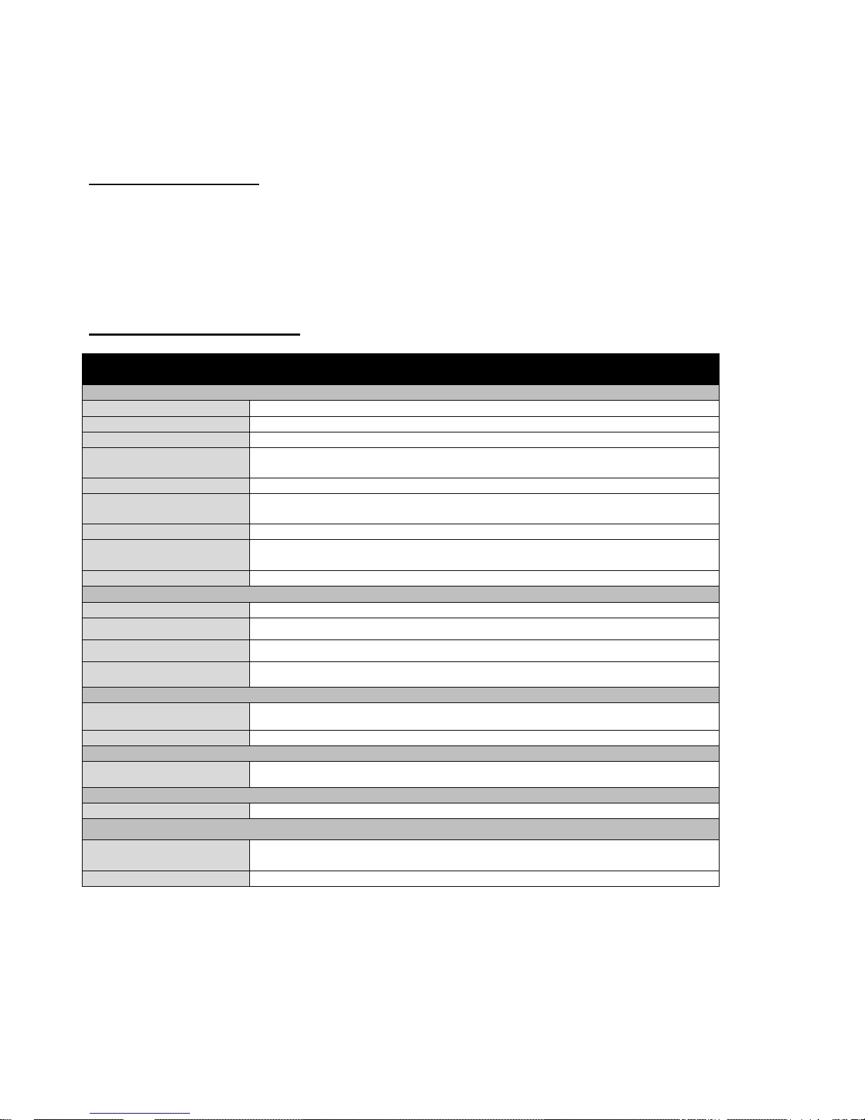
Product Specification
Model Name
LDS410DF-1P
Display
Panel Size
19”
Resolution
1280 x 1024
Pixel Pitch
0.294 (H) x 0.294 (V)
Brightness
250 cd/
Contrast Ratio
500:1 (typ.)
Viewing Angles
(Up/Down/Left/Right)
85°/85°/85°/85°
Active Display Area,
216.96 (H) x 135 (V)
Max Colors
16.2 M colors,
8 bits/color
Glass
AR Glass
Mechanical
Dimensions, mm
517 x 399.7 x 44 mm
Housing
1U Drawer
Display angle adjustment
0° ~ 110°
Mounting
Rack Mount
Input/ Output Connectors
VGA Input
1 x D-SUB 15pin (Female)
DC Input
1 x AC Power Input
User Controls
OSD Control
+, - , power , Left , Right
Power Specifications
Power Input
AC 100-240V
Certificate
Military (Compliance)
MIL-STD 810G
MIL-STD 461F
CE / FCC
CE / FCC
Page 3

2
Outline drawing
Front Side
With Rack Chassis
Page 4

3
Dimension
Page 5

4
I/O Description
VGA
VGA
Pin №
Signal
Name
Pin №
Signal
Name 1 L 2 N 3 E
Pin №
Signal
Name
Pin №
Signal
Name
1
RED
2
GREEN
3
BLUE
4
NC 5 GND
6
AGND
7
AGND
8
AGND
9
+5V
10
GND
11
NC
12
SDA
13
H Sync
14
V Sync
15
SCL
Page 6

5
Chapter2: Installation
Step 1
Mount the Rack Drawer LCD on Rack-Mount Chassis with screws
Step 2
Connect the power cord to the rack LCD monitor and AC outlet
Connect the VGA to the PC source
Step 3
Turn on the unit by the front side OSD “Power On”
Page 7

6
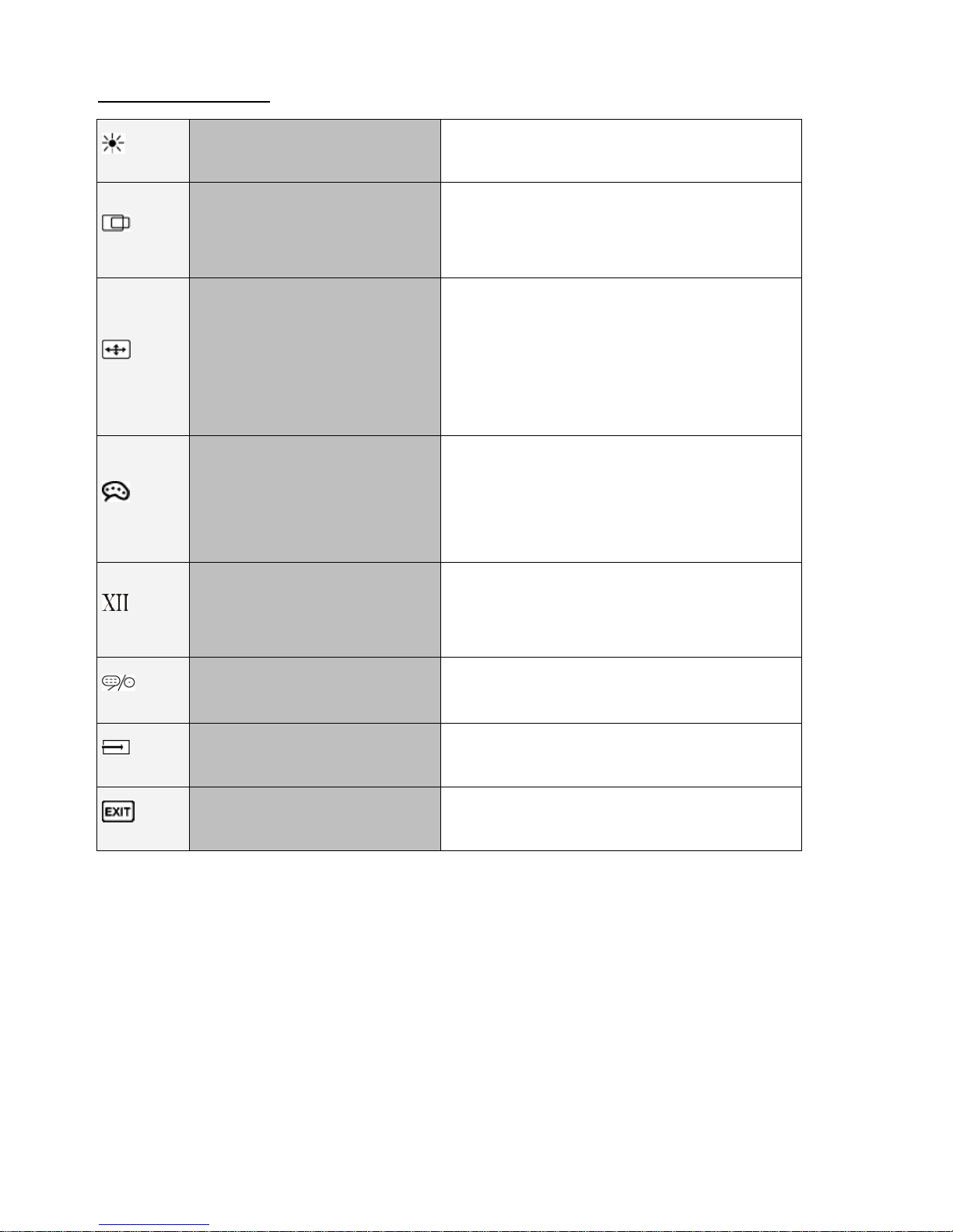
Chapter3: OSD Operation
OSD Key define
Icon
Function
Decrease the value / Select up
Increase the value / Select down
Power switch
Select left
Select right / Call main OSD menu
Page 8
7
OSD Navigation
BRICONTRAST
BRIGHTNESS
CONTRAST
POSITION
Only support VGA mode
H position
V position
IMAGE
Only support VGA mode
Auto Adjustment
Clock
Phase
White Balance
COLOR
USER
9300K
6500K
ADC RIGHTNESS
GAMMA
GAMMA0
GAMMA1
GAMMA2
CHANNEL
ANALOG
RECALL
YES
NO
OSD EXIT
YES
NO
Page 9

8
BRICONTRAST
OSD Icon
Sub-menu
Settings
Note
BRICONTRAST
BRIGHTNESS
slider bar
Default 50
Use to adjust the screen’s brightness. Range 0 to 100
CONTRAST
slider bar
Default 50
Use to adjust the screen’s contrast. Range 0 to 100
POSITION (VGA mode only)
OSD Icon
Sub-menu
Settings
Note
POSITION
H POSITION
slider bar
Default 50
Use to adjust the image to the left or right on the screen.
Range 0 to 100
V POSITION
slider bar
Default 50
Use to adjust the image up or down on the screen. Range 0 to 100
IMAGE (VGA mode only)
OSD Icon
Sub-menu
Settings
Note
IMAGE
AUTO
Select and execute
Use to choose the best settings for the current input signal
CLOCK
slider bar
Default 50
Use to adjust the value of horizontal image. Range 0 to 100
PAHSE
slider bar
Default 50
Use to adjust the phase control (Phase adjustment may be required to
optimize the display quality)
WHITE BALANCE
Select and execute
Use to set RGB signal voltage level
Page 10

9
COLOR
OSD Icon
Sub-menu
Settings
Note
COLOR
USER
R.G.B slider bar
Choose RED/GREEN/BLUE to set value of color temperature
brightness to suit your own preference
9300K
Select and execute
Use to set value of monitor for the CIE coordinate 9300 color
temperature
6500K
Select and execute
Use to set value of monitor for the CIE coordinate 6500 color
temperature
ADC RIGHTNESS
slider bar
Default 50
Set value of monitor for ADC Brightness. Range 0 to 100
GAMMA
OSD Icon
Sub-menu
Settings
Note
GAMMA
GAMMA 0
Select and execute
Default
GAMMA0
Choose the parameter of GAMMA 0 as default setting.
GAMMA 1
Select and execute
Choose the parameter of GAMMA 1 as default setting.
GAMMA 2
Select and execute
Choose the parameter of GAMMA 2 as default setting.
CHANNEL
OSD Icon
Sub-menu
Settings
Note
CHANNEL
ANALOG
Select and execute
Switch the setting of signal input to Analog mode
Page 11

10
RECALL
OSD Icon
Sub-menu
Settings
Note
RECALL
YES
Select and execute
Recall the factory default setting
NO
Select and execute
Return to main menu
EXIT
OSD Icon
Sub-menu
Settings
Note
EXIT
YES
Select and execute
Exit the OSD menu
NO
Select and execute
Return to main menu
Page 12
11
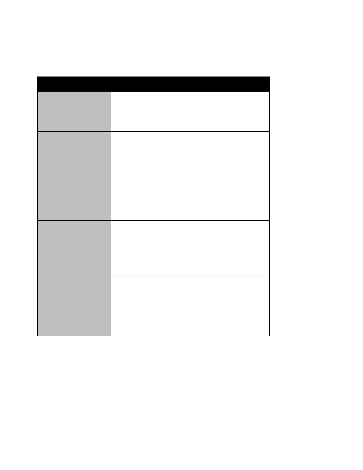
Chapter 4: Troubleshooting
If your monitor fails to operate correctly, check the following chart for possible solution before
calling for repairs:
Condition
Check Point
The picture does not
appear
• Check if the signal cable is firmly seated in the
socket.
• Check if the Power is ON at the computer
• Check if the brightness control is at the
appropriate position, not at the minimum.
The screen is not
synchronized
• Check if the signal cable is firmly seated in the
socket.
• Check if the output level matches the input level
of your computer.
• Make sure the signal timings of the computer
system are within the specification of the
monitor.
• If your computer was working with a CRT
monitor, you should check the current signal
timing and turn off your computer before you
connect the VGA Cable to this monitor.
The position of the
screen is not in the
center
• Adjust the H-position, and V-position, or
Perform the Auto adjustment.
The screen is too
bright (too dark)
• Check if the brightness or contrast control is at
the appropriate position, not at the Maximum
(Minimum).
The screen is
shaking or waving
• Perform the Auto adjustment.
• Moving all objects which emit a magnetic field
such as motor or transformer, away from the
monitor.
• Check if the specific voltage is applied.
• Check if the signal timing of the computer
system is within the specification of monitor.
Page 13

12
Appendix A: Frequency Table
The choice of supported modes depends on the monitor native resolution.
VGA
№
Resolution
Frequency
(Hz)
1
640x480
60 2 640x480
72
3
640x480
75
4
800x600
56
5
800x600
60 6 800x600
72 7 800x600
75 8 1024x768
60
9
1024x768
70
10
1024x768
75
11
1280x1024
60
12
1280x1024
75
13
1366x768
60
14
1600x1200
60
15
1680x1050
60
16
1920x1200
60
17*
1920x1080
60
Page 14

13
Appendix B: Military Grade Standard
Page 15

14
NOTES
_____________________________________________________________________________
_____________________________________________________________________________
_____________________________________________________________________________
_____________________________________________________________________________
_____________________________________________________________________________
_____________________________________________________________________________
_____________________________________________________________________________
_____________________________________________________________________________
_____________________________________________________________________________
_____________________________________________________________________________
_____________________________________________________________________________
_____________________________________________________________________________
_____________________________________________________________________________
_____________________________________________________________________________
_____________________________________________________________________________
_____________________________________________________________________________
_____________________________________________________________________________
_____________________________________________________________________________
_____________________________________________________________________________
_________________________
Page 16

15
Winmate Inc.
9F, No.111-6,Shing-De Rd., San-Chung City,
Taipei 241, Taiwan, R.O.C
Tel: 886-2-8511-0288
Fax: 886-2-8511-0211
Email: sales@winmate.com.tw
Official website: http://www.winmate.com.tw
 Loading...