

Page 1

ID31 Motherboard
3.5” Fanless SBC with Intel ® Atom Dual Core N2600 1.6GHz Processor,
VGA, LVDS, Dual Giga Ethernet,
and Mini-PCIe Interface
User Manual / Engineering Spec.
Version 1.1
Page 2

ID31 Motherboard User Manual
II
ID31 Motherboard User Manual /
Engineering Spec.
FCC Statement
This device complies with part 15 FCC rules. Operation is subject to
the following two conditions:
This device may not cause harmful interference.
This device must accept any interference received including
interference that may cause undesired operation.
This equipment has been tested and found to comply with the limits for a class "a"
digital device, pursuant to part 15 of the FCC rules. These limits are designed to
provide reasonable protection against harmful interference when the equipment is
operated in a commercial environment. This equipment generates, uses, and can
radiate radio frequency energy and, if not installed and used in accordance with the
instruction manual, may cause harmful interference to radio communications.
Operation of this equipment in a residential area is likely to cause harmful
interference in which case the user will be required to correct the interference at him
own expense.
Page 3

ID31 Motherboard User Manual
III
ID31 Motherboard User Manual /
Engineering Spec.
Copyright Notice
No part of this document may be reproduced, copied, translated, or transmitted in any
form or by any means, electronic or mechanical, for any purpose, without the prior
written permission of the original manufacturer.
Trademark Acknowledgement
Brand and product names are trademarks or registered trademarks of their respective
owners.
Disclaimer
We reserve the right to make changes, without notice, to any product, including
circuits and/or software described or contained in this manual in order to improve
design and/or performance. We assume no responsibility or liability for the use of the
described product(s), conveys no license or title under any patent, copyright, or masks
work rights to these products, and makes no representations or warranties that these
products are free from patent, copyright, or mask work right infringement, unless
otherwise specified. Applications that are described in this manual are for illustration
purposes only. Winmate Communication Inc. makes no representation or warranty
that such application will be suitable for the specified use without further testing or
modification.
Warranty
We warrant that each of its products will be free from material and workmanship
defects for a period of one year from the invoice date. If the customer discovers a
defect, We will, at its option, repair or replace the defective product at no charge to
the customer, provided it is returned during the warranty period of one year, with
transportation charges prepaid. The returned product must be properly packaged in its
original packaging to obtain warranty service.
If the serial number and the product shipping data differ by over 30 days, the inwarranty service will be made according to the shipping date. In the serial numbers
the third and fourth two digits give the year of manufacture, and the fifth digit means
the month (e. g., with A for October, B for November and C for December).
For example, the serial number 1W11Axxxxxxxx means October of year 2011.
Page 4

ID31 Motherboard User Manual
4
ID31 Motherboard User Manual /
Engineering Spec.
Packing List
Before using this Motherboard, please make sure that all the items listed below are
present in your package:
ID31 Motherboard
User Manual
HDD SATA Cable
User’s Manual & Driver CD
If any of these items are missing or damaged, contact your distributor or sales
representative immediately.
Customer Service
We provide service guide for any problem as follow steps: The first, contact with
your distributor, sales representative, or our customer service center for technical
support if you need additional assistance. You may have the following information
ready before you call:
Product serial number
Peripheral attachments
Software (OS, version, application software, etc.)
Description of complete problem
The exact wording of any error messages
In addition, free technical support is available from our engineers every business day.
We are always ready to give advice on application requirements or specific
information on the installation and operation of any of our products. Please do not
hesitate to call or e-mail us.
Page 5

ID31 Motherboard User Manual
5
ID31 Motherboard User Manual /
Engineering Spec.
Safety Precautions
Warning!
Always completely disconnect the power cord from your chassis
whenever you work with the hardware. Do not make connections
while the power is on. Sensitive electronic components can be
damaged by sudden power surges. Only experienced electronic
personnel should open the PC chassis.
Caution!
Always ground yourself to remove any static charge before
touching the CPU card. Modern electronic devices are very
sensitive to static electric charges. As a safety precaution, use a
grounding wrist strap at all times. Place all electronic components
in a static-dissipative surface or static-shielded bag when they are
not in the chassis.
Page 6

ID31 Motherboard User Manual
6
ID31 Motherboard User Manual /
Engineering Spec.
Safety and Warranty
1. Please read these safety instructions carefully.
2. Please keep this user's manual for later reference.
3. Please disconnect this equipment from any AC outlet before cleaning. Do not use
liquid or spray detergents for cleaning. Use a damp cloth.
4. For pluggable equipment, the power outlet must be installed near the equipment
and must be easily accessible.
5. Keep this equipment away from humidity.
6. Put this equipment on a reliable surface during installation. Dropping it or letting
it fall could cause damage.
7. The openings on the enclosure are for air convection. Protect the equipment from
overheating. DO NOT COVER THE OPENINGS.
8. Make sure the voltage of the power source is correct before connecting the
equipment to the power outlet.
9. Position the power cord so that people cannot step on it. Do not place anything
over the power cord.
10. All cautions and warnings on the equipment should be noted.
11. If the equipment is not used for a long time, disconnect it from the power source
to avoid damage by transient over-voltage.
12. Never pour any liquid into an opening. This could cause fire or electrical shock.
13. Never open the equipment. For safety reasons, only qualified service personnel
should open the equipment.
14. If any of the following situations arises, get the equipment checked by service
personnel:
A. The power cord or plug is damaged.
B. Liquid has penetrated into the equipment.
C. The equipment has been exposed to moisture.
D. The equipment does not work well, or you cannot get it to work according to
the user’s manual.
E. The equipment has been dropped and damaged.
F. The equipment has obvious signs of breakage.
15. Do not leave this equipment in an uncontrolled environment where the storage
temperature is below -20° C (-4°F) or above 60° C (140° F). It may damage the
equipment.
Page 7

ID31 Motherboard User Manual
VII
ID31 Motherboard User Manual /
Engineering Spec.
Revision History
Version
Date
Note
Author
1.0
2012.07.23
Initial Draft
Henry Hsu
1.1
2015.05.08
Revise content
Tom Huang
Page 8

ID31 Motherboard User Manual
VIII
ID31 Motherboard User Manual /
Engineering Spec.
Contents
CHAPTER 1 GENERAL INFORMATION ........................................ 2
1.1 INTRODUCTION................................................................................ 2
1.2 FEATURE ................................................................................................. 2
1.3 MOTHERBOARD SPECIFICATIONS ....................................................... 3
1.4 FUNCTION BLOCK ........................................................................... 4
1.5 BOARD DIMENSIONS ........................................................................ 5
CHAPTER 2 INSTALLATIONS ............................................................ 7
2.1 MEMORY MODULE(SO-DIMM)INSTALLATION ........................... 7
2.2 I/O EQUIPMENT INSTALLATION ............................................................ 8
2.3 JUMPERS AND CONNECTORS............................................................ 9
2.4 JUMPER SETTING ........................................................................... 11
2.5 CONNECTORS AND PIN ASSIGNMENT ............................................. 14
CHAPTER 3 GRAPHIC DRIVER INSTALLATION ..................... 21
3.1 STANDARD CMOS FEATURE ..................................................................... 21
3.2 PANEL RESOLUTION SETTING ............................................................ 25
CHAPTER 4 CHIPSET DRIVER INSTALLATION ....................... 28
4.1 STANDARD CMOS FEATURES ................................................................ 28
CHAPTER 5 ETHERNET DRIVER INSTALLATION ................... 32
INSTALLATION OF ETHERNET DRIVER ........................................................ 32
CHAPTER 6 AUDIO DRIVER INSTALLATION ........................... 36
6.1 INTRODUCTION ................................................................................. 36
6.2 INSTALLATION OF AUDIO DRIVER .................................................. 36
CHAPTER 7 AMI BIOS SETUP ...................................................... 43
7.1 ADVANCED SETTING .......................................................................... 44
Page 9

ID31 Motherboard User Manual
1
ID31 Motherboard User Manual /
Engineering Spec.
1
General Information
This chapter includes the ID31 Motherboard background
information.
Sections include:
Introduction
Feature
Motherboard Specification
Function Block
Board Dimensions
C H A P T E R
Page 10

ID31 Motherboard User Manual
2
ID31 Motherboard User Manual /
Engineering Spec.
Chapter 1 General Information
1.1 Introduction
The ID31 SBC is integrated with Intel
®
NM10 express chipset, 17x17mm,
and Atom N2600 Processor. Intel Atom Processor with 32nm low power
design enables down to 50% less average power consumption and the
chipset delivers up to 4x improvement in graphics performance and
enables up to 50% higher data transfer bus speed rate.
In peripheral connectivity, ID31 SBC features with Mini-PCIe I/O ports,
one Serial ATA connectors, five Serial Port (One Connector; Four Pin
Header ) and Six Hi-Speed USB 2.0 connectors( Two Connector ; Four Pin
Header ) .Additionally, ID31 SBC build-in a 12~24V DC-IN power
adapter.
Thus, the ID31 SBC is designed to satisfy most of the applications in the
industrial computer market, such as Gaming, POS, KIOSK, Industrial
Automation, and Programmable Control System. It is a compact design to
meet the demanding performance requirements of today’s business and
industrial applications.
1.2 Feature
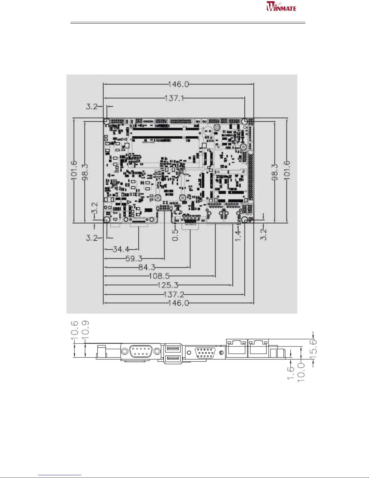
3.5-inch Form Factor ( 146mm x 102mm)
Supports Intel
®
Atom N2600 1.6GHz processor
System memory up to 4GB DDR3 800/1066, SO-DIMM
Intel NM10 Chipset
Intel
®
Graphic Accelerator 3600 Integrated Graphics Engine.
Dual Broadcom BCM57780 GbE controller
2 x Mini PCIe(one for wireless, one for SATA SSD), 5 X COM, 6 x
USB2.0, 1 x SATA, 8 x GPIO ports, 1 x DVI
Page 11

ID31 Motherboard User Manual
3
ID31 Motherboard User Manual /
Engineering Spec.
1.3 Motherboard Specifications
CPU Type
Intel Atom Dual Core N2600 Processor
CPU Speed
1.6GHz
Chipset
Intel NM10
BIOS
AMI 4Mbit Flash
Graphic
Intel® Graphic Accelerator 3600 support DX9, OGL3.0
LCD interface
Single-channel 24 bit LVDS Up to 1440 x 900 @ 60Hz
Resolution
VGA mode: Up to 1920 x 1200 @ 60Hz
DVI: 1920 x 1200 @ 60Hz
LAN
2 x Giga LAN (Broadcom BCM57780 GbE controller )
Memory Type
1 x SO-DIMM socket, supports up to 4GB DDR3 800/1066
Super I/O
Fintek F81865
Sound
Realtek ALC886 HD Audio Codec
USB
6 ports, USB 2.0 (2 x USB Connector, 4 x USB
pin-header )
Edge Connectors
1 x DC-IN Jack (+12~24V)
1 x VGA out connector
2 x Gigabit LAN RJ-45
1 x RS232/422/485
1 x Dual USB stack connector
On Board
Pin-Header
Connectors
1 x SATA connector for SATAI/II 3.0 Gb/s 1
x 10pins pin-header for Front Panel(2x5)
1 x 8pins pin-header for 5V/12V external power
1 x 3pins pin-header for CPU Fan
1 x 2pins pin-header for 5V external power
1 x 2pins pin-header for 12V external power
1 x 12pins pin-header for Front Audio(2x6) 2
x 8pins pin-header for USB (2X4)
1 x 10pins Digital I/O(2x5)
4 x 10pins pin-header for COM2/3/4/5 (2X5)
1 x 2-pin Power-input connector
1 x 20pins Connector for LVDS
1 x 20pins Connector for DVI
1 x 3pins digital panel backlight brightness controller
1 x 7pins digital panel inverter
Power Connector
Input: 2-pin Power-input connector
Expansion Slots
1 x Mini PCIe slot for wireless, 1 x Mini PCIe slot for SATA
SSD
Form Factor
3.5 inch
Dimensions
146mm x 102mm
Mechanical &
environmental
Operating temperature: 0 deg. C to 60 deg. C
Operating Humidity: 10 ~ 90% Relative humidity,
non-condensing
Shock: Operating 15G, 11ms duration
Vibration: Operating 5 Hz~500Hz / 1Grms / 3 Axis
Certification: CE, FCC, RoHS
Page 12
ID31 Motherboard User Manual
4
ID31 Motherboard User Manual /
Engineering Spec.
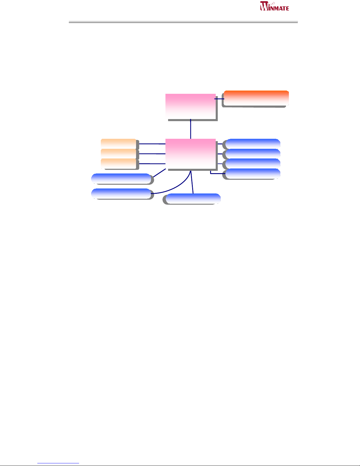
1.4 Function Block
D2600 CPU
SO-DIMM x 1
DDR3 800/1066 Max.4GB
3GB/s
VGA
LVDS
DVI
SATA II
Intel NM10
Chipset
LAN
USB
Audio
Super IO
1GB/s
480MB/s
RReeaalltteekk AALLCC88886
6
FFiinntteekk FF881188666
6
Mini PCIe
BIOS
AAMMI
I
Page 13
ID31 Motherboard User Manual
5
ID31 Motherboard User Manual /
Engineering Spec.
1.5 Board dimensions
Page 14

ID31 Motherboard User Manual
6
ID31 Motherboard User Manual /
Engineering Spec.
2
Installations
This chapter provides information on how to use the
jumps and connectors on the ID31 Motherboard.
The Sections include:
Memory Module Installation
I / O Equipment Installation
Setting the Jumpers
Connectors on ID31 Motherboard
C H A P T E R
Page 15
ID31 Motherboard User Manual
7
ID31 Motherboard User Manual /
Engineering Spec.
Chapter 2 Installations
2.1 Memory Module(SO-DIMM)Installation
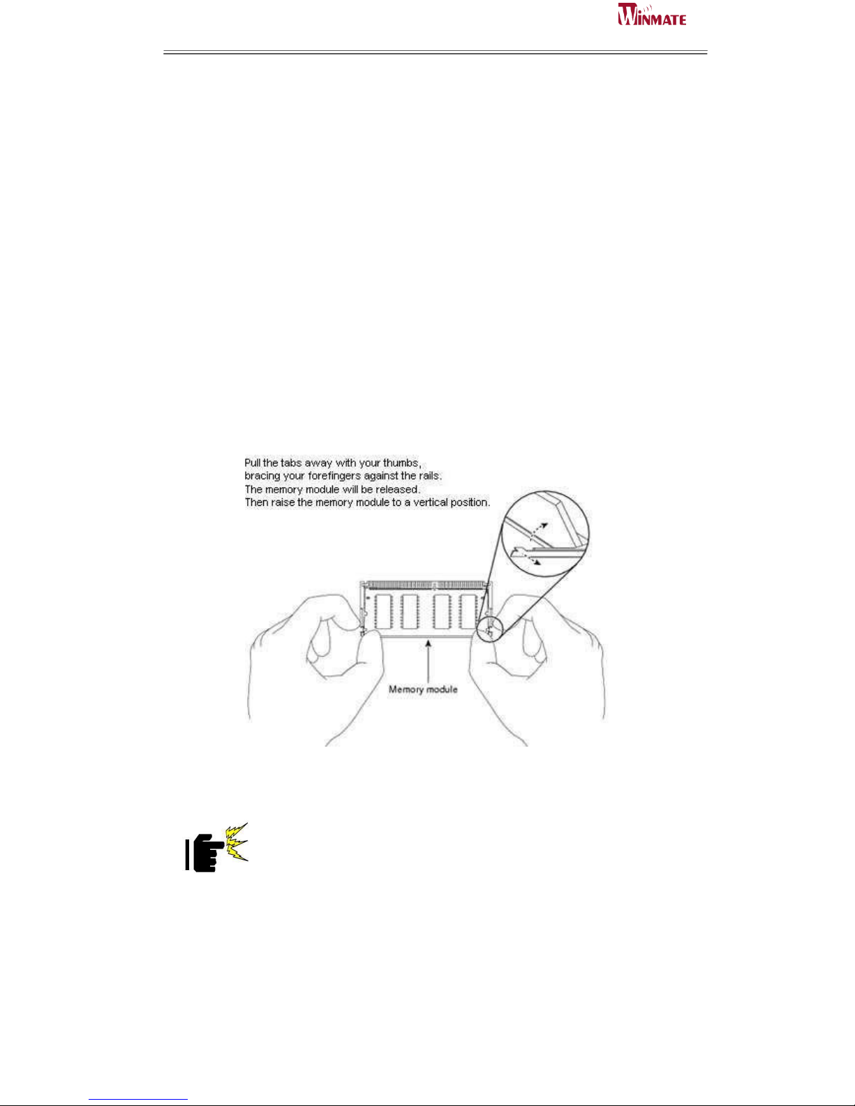
The ID31 Motherboard provides one 204-pin SODIMM slot. The socket supports up
to 4GB DDR3 1066 SDRAM. When installing the Memory device, please follow the
steps below:
Step.1. Firmly insert the SO-DIMM at an angle into its slot. Align the SO-DIMM on
the slot such that the notch on the SO-DIMM matches the break on the slot.
Step.2. Press downwards on SO-DIMM until the retaining clips at both ends fully
snap back in place and the SO-DIMM is properly seated.
Caution!
The SO-DIMM only fits in one correct orientation. It will cause
permanent damage to the development board and the SO-DIMM if
the SO-DIMM is forced into the slot at the incorrect orientation.
Page 16

ID31 Motherboard User Manual
8
ID31 Motherboard User Manual /
Engineering Spec.
2.2 I/O Equipment Installation
2.2.1 12~24V DC-IN
The Motherboard allows plugging 12~24V DC-IN jack on the board without another
power module converter under power consumption by Intel Atom N2600 1.6GHz
Processor in NM10 chipset.
2.2.2 Serial COM ports
Two RS-232 connectors build in the rear I/O. One optional COM ports support
RS-422/485. When an optional touch-screen is ordered with PPC, serial com port can
connect to a serial or an optional touch-screen.
※Without power/reset OSD, you can short circuit pin5 & 6 of the onboard panel
connector to boot up the motherboard.
2.2.3 External VGA
The Motherboard has one VGA port that can be connected to an external CRT/ LCD
monitor. Use VGA cable to connect to an external CRT / LCD monitor, and connect
the power cable to the outlet. The VGA connector is a standard 15-pin D-SUB
connector.
2.2.4 Ethernet interface
The Motherboard is equipped with Broadcom BCM57780 chipset which is fully
compliant with the PCI 10/100/1000 Mbps Ethernet protocol compatible. It is
supported by major network operating systems. The Ethernet ports provide two
standard RJ-45 jacks.
2.2.5 USB ports
Four USB devices (Two with pin headers) may be connected to the system though an
adapter cable. Various adapters may come with USB ports. USB usually connect the
external system to the system. The USB ports support hot plug-in connection.
Whatever, you should install the device driver before you use the device.
2.2.6 Audio function
The Audio 7.1 channel capabilities are provided by a Realtek ALC886 chipset
supporting digital audio outputs. The audio interface includes two jacks: line-in and
line-out.
Page 17
ID31 Motherboard User Manual
9
ID31 Motherboard User Manual /
Engineering Spec.
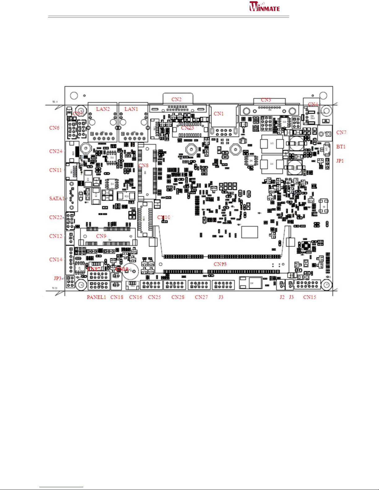
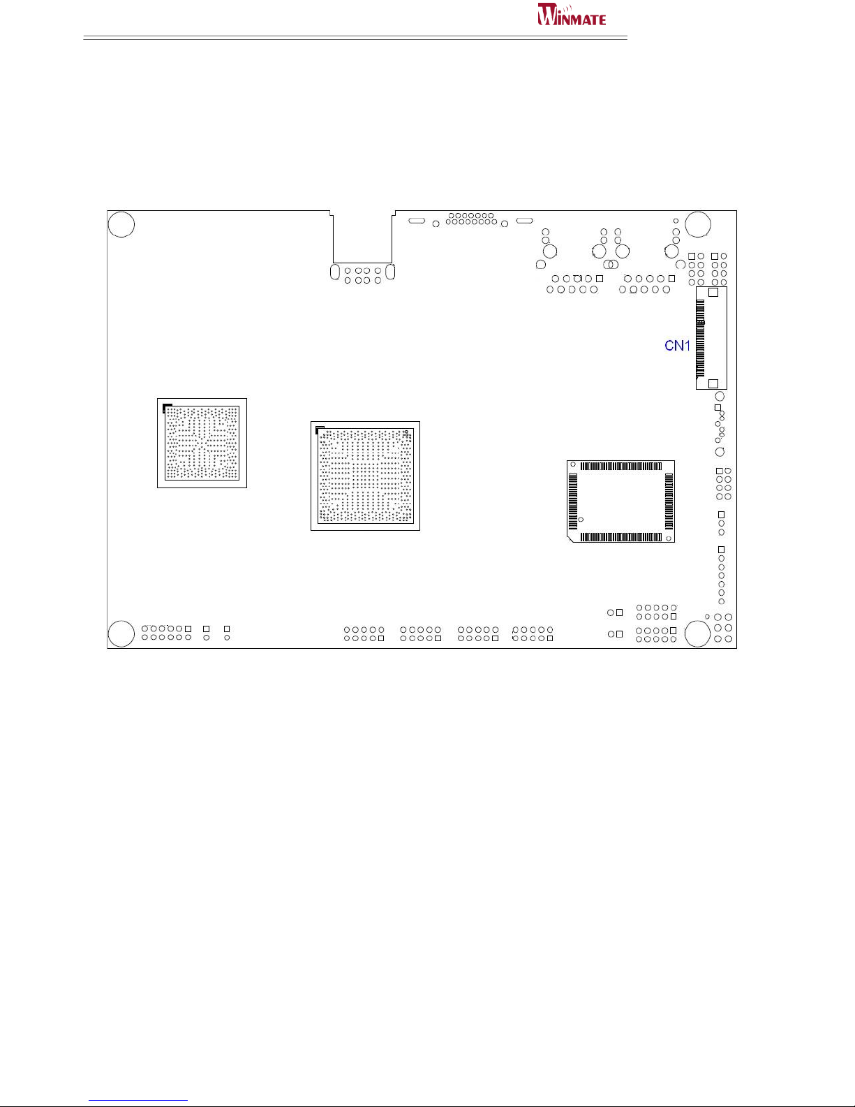
2.3 Jumpers and Connectors
TOP
Page 18
ID31 Motherboard User Manual
10
ID31 Motherboard User Manual /
Engineering Spec.
BOTTOM
Page 19
ID31 Motherboard User Manual
11
ID31 Motherboard User Manual /
Engineering Spec.
2.4 Jumper Setting
A pair of needle-nose pliers may be helpful when working with jumpers. If you have
any doubts about the best hardware configuration for your application, contact your
local distributor or sales representative before you make any changes. Generally, you
simply need a standard cable to make most connections.
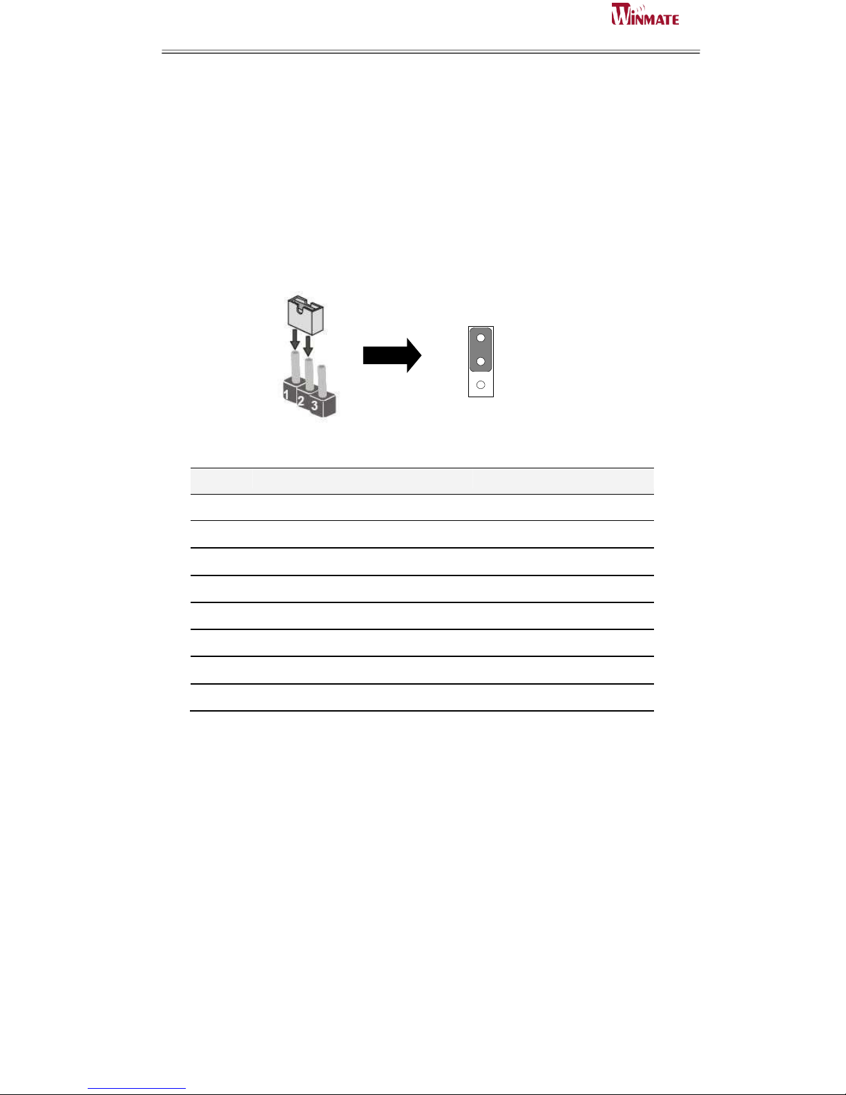
The jumper setting diagram is as below. If a jumper shorts pin 1 and pin 2, the setting
diagram is shown as the right one.
1
2
3
The following tables list the function of each of the board's jumpers.
Label
Function
Note
JP1
Clear CMOS
3x1 header , pitch 2.0mm
JP3
LVDS VOLTAGE
2x3 header , pitch 2.0mm
JP4
RS232 / RS422 / RS485 Selector
2x3 header , pitch 2.0mm
JP5
PWM /DC Selector
3x1 header , pitch 2.0mm
JP8
RS232 / RS422 / RS485 Selector
3x4 header , pitch 2.0mm
JP9
Inverter Power Selector
3x1 header , pitch 2.0mm
JP10
Inverter PWM Level Selector
3x1 header , pitch 2.0mm
JP11
Brightness Mode Selector
3x1 header , pitch 2.0mm
Page 20
ID31 Motherboard User Manual
12
ID31 Motherboard User Manual /
Engineering Spec.
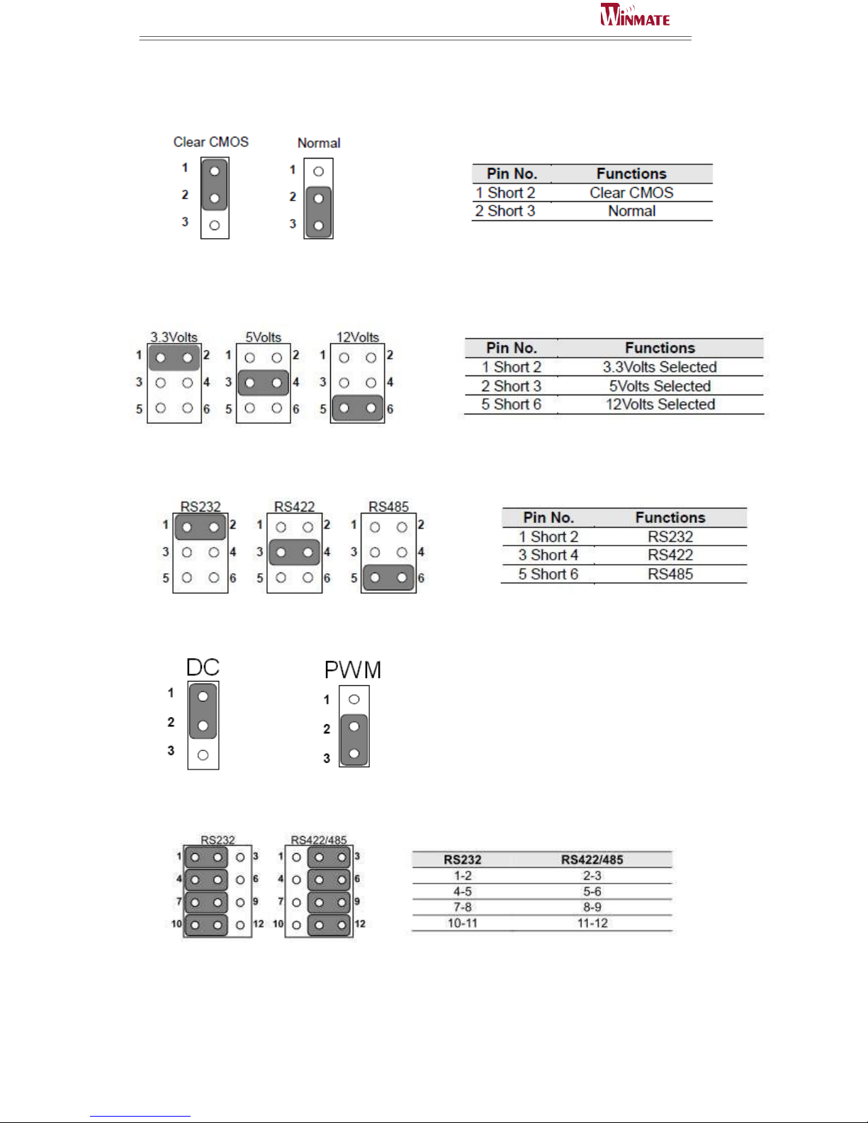
2.4.1 JP1 : Clear CMOS
2.4.2 JP3 : LCD Panel Voltage Select
2.4.3 JP4: RS232 / RS422 / RS485 Selector for CON port
2.4.4 JP5: PWM/DC Selector
2.4.5 JP8 : RS232 / RS422 / RS485 Selector for CON port
.
Page 21
ID31 Motherboard User Manual
13
ID31 Motherboard User Manual /
Engineering Spec.
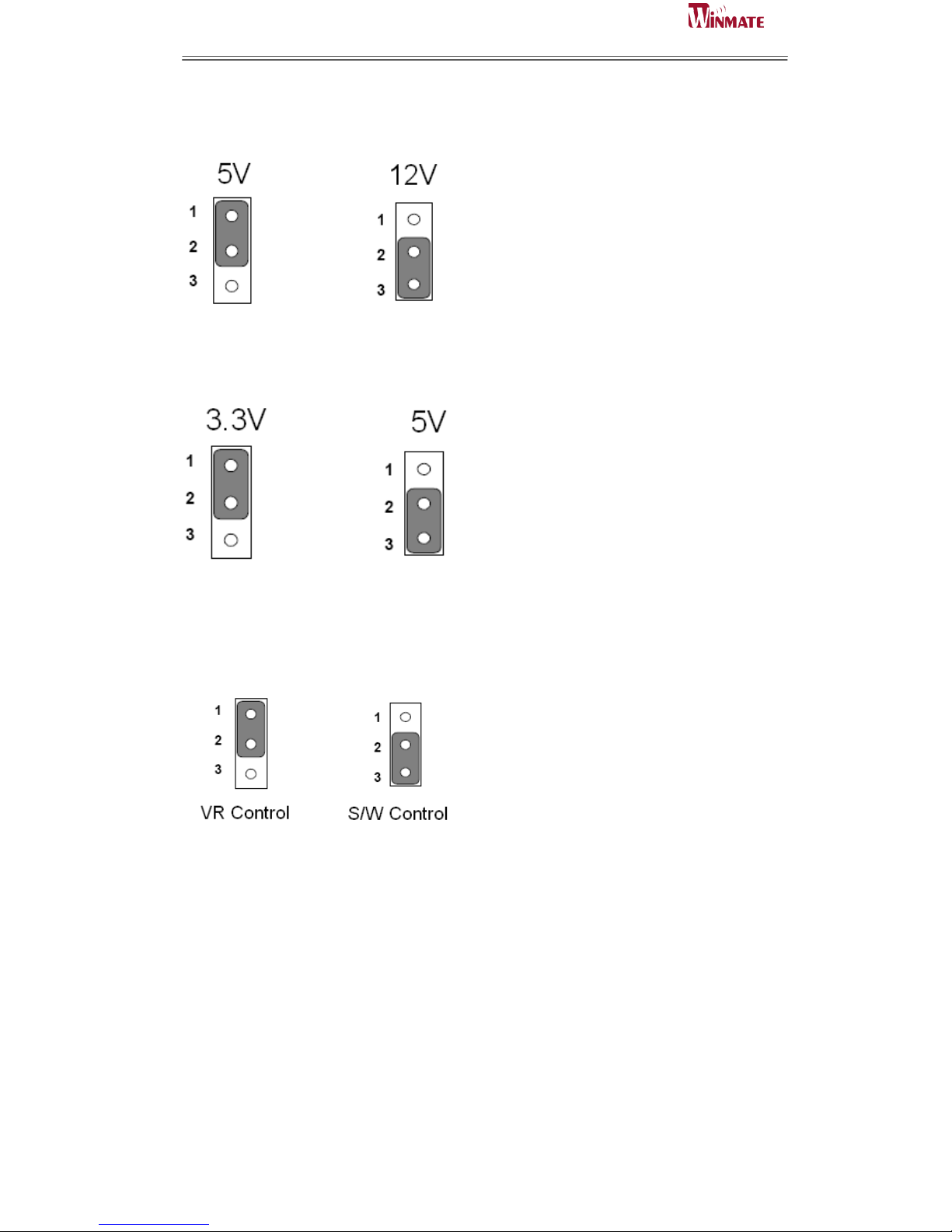
2.4.5 JP9 : Inverter Power Selector
2.4.6 JP10 : Inverter Power Selector
2.4.6 JP11 : Brightness Mode Selector
Page 22

ID31 Motherboard User Manual
14
ID31 Motherboard User Manual /
Engineering Spec.
2.5 Connectors and Pin Assignment
The table below lists the function of each of the board’s connectors.
Label
Function
Note
CN10
LVDS LCD Output Connector
2x10 Pin, 1.25mm
JP1
Digital Panel Backlight Brightness
Control
3x1 header, pitch 2.54mm
CON3
Digital Panel Backlight Inverter Power 7x1 header, pitch 2.54mm
VGA
VGA Output
DB15
COM Port
COM1 for RS232/422/485
DB9
J4
COM2 for RS232
2x5 header
CN27
COM3 for RS232
2x5 header
CN28
COM4 for RS232
2x5 header
CN25
COM5 for RS232
2x5 header
CN15
Audio connector
2x6 header
CN16
SM Bus Connector
1x4 header, pitch 1.0mm
CN5
USB PIN HEADER
4x2 Pin Header
CN6
USB PIN HEADER
4x2 Pin Header
CPU_FAN
FAN CONNECTOR
3x1 Pin Header
PANEL1
System Function Connector
5x2 header ,pitch 2.0mm
CN11
UART Connector
1x6 header, pitch 1.0mm
CN12
VR Connector
3x1 Pin Header
CN14
Inverter Connector
7x1 header, pitch 2.0mm
CN18
12V External Power
2x1 header, pitch 2.0mm
CN19
5V External Power
2x1 header, pitch 2.0mm
CN22
12V/5V External Power
4x2 header ,pitch 2.54mm
CN7
12~24V DC Jack
2 Pin Jack
CN17
Digital I/O
2x5 Pin header
J2/J3
Amplifier
2 Pin header
CN23
DVI LCD Output Connector
20DP-1.25V
CN9
Mini PCIe slot for SSD
Mini PCIe slot
CN10
Mini PCIe slot for WLAN
Mini PCIe slot
* Not Default Connector
Page 23
ID31 Motherboard User Manual
15
ID31 Motherboard User Manual /
Engineering Spec.
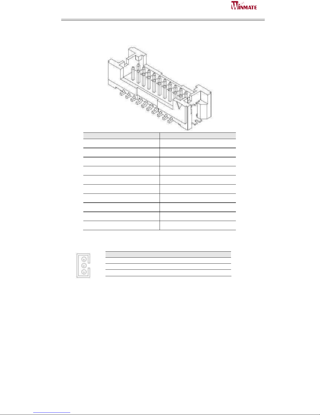
2.5.1 CN10: LVDS Connector
Pin No.
SYMBOL
Pin No.
SYMBOL
1
GND
2
LVDS_TX0_DN
3
GND
4
LVDS_TX0_DP
5
GND
6
LVDS_TX1_DN
7
GND
8
LVDS_TX1_DP
9
GND
10
LVDS_TX2_DN
11
N/C
12
LVDS_TX2_DP
13
LCDVDD
14
LVDS_CLK_DN
15
LCDVDD
16
LVDS_CLK_DP
17
LCDVDD
18
LVDS_TX3_DN
19
LCDVDD
20
LVDS_TX3_DP
2.5.2 CN12: Digital Panel Backlight Brightness Control
Pin No. SYMBOL
1 5V
2 Black Light Control
3 GND
Page 24
ID31 Motherboard User Manual
16
ID31 Motherboard User Manual /
Engineering Spec.
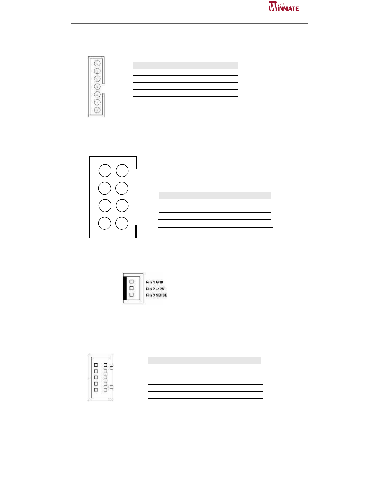
2.5.3 CN14: Inverter Power
1 Inverter Power
2 Inverter Power
3 Inverter Power
4 GND
5 Black Light Control
6 GND
7 Backlight ON/OFF
2.5.4 CN5/CN6: USB PIN HEADER
USB
Pin SYMBOL Pin SYMBOL
8 GND
7
GND
2.5.5 CPU_FAN: FAN CONNECTOR
CPU_FAN
2.5.6 PANEL1: Front Panel System Function Connector
Without power/reset OSD, short circuit pin 5 and 6 together to boot up the motherboard.
2 1
4 3
6 5
8 7
10
9
Pin SYMBOL Pin SYMBOL
2 3.3V 1
PW_LED+
4 HD_LED- 3
GND
6
GND
5
PW_BT1
8
Reset#
7
GND
10 5VSB
9 WiFi LED#
2
4
USB 5V
USB_P6-
1
3
USB 5V
USB_P7-
6
USB_P6+
5
USB_P7+
Pin No. SYMBOL
2 1
4 3
6 5
8
7
Page 25
ID31 Motherboard User Manual
17
ID31 Motherboard User Manual /
Engineering Spec.
1 2 3 4 5 6 7 8 9
10
11
12
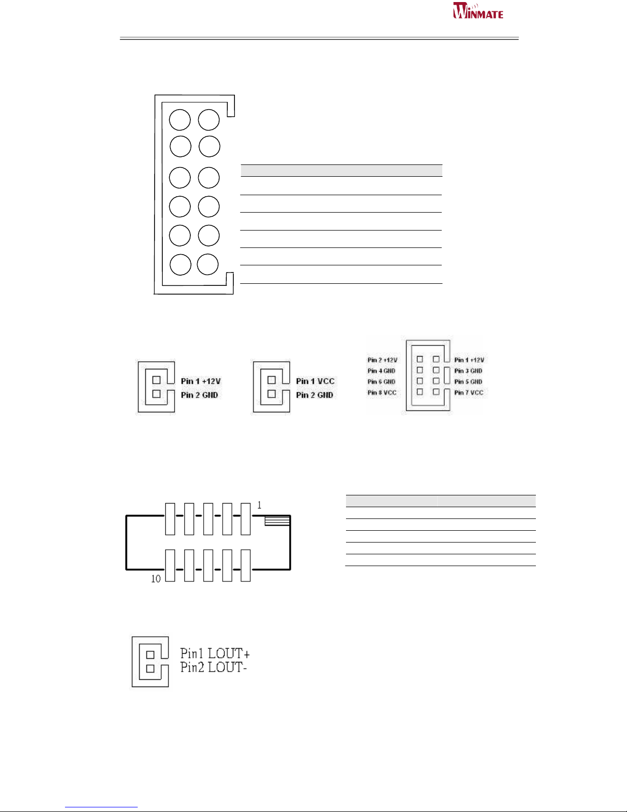
2.5.7 AUDIO1: Audio Connector
2
AZ_FOUT_L
1
AZ_FOUT_R
4
AUGND
3
+5VA
6
LINE1_L
5
LINE1_R
8
MIC1_L
7
MIC1_R
10
SW_D
9
AUGND
12
SW_C
11
SW_B
2.5.8 CN18/CN19/CN22: External Power
CN18 CN19
CN22
2.5.9 CN17: Digital I/O Connector
2.5.10 J2(Left)/J3(Right): Amplifier
Pin
SYMBOL
Pin
SYMBOL
2
Vcc
1
GND
4
Out1
3
Out3
6
Out0
5
Out2
8
IN1 7 IN3
10
IN0 9 IN2
Pin
SYMBOL
Pin SYMBOL
Page 26
ID31 Motherboard User Manual
18
ID31 Motherboard User Manual /
Engineering Spec.
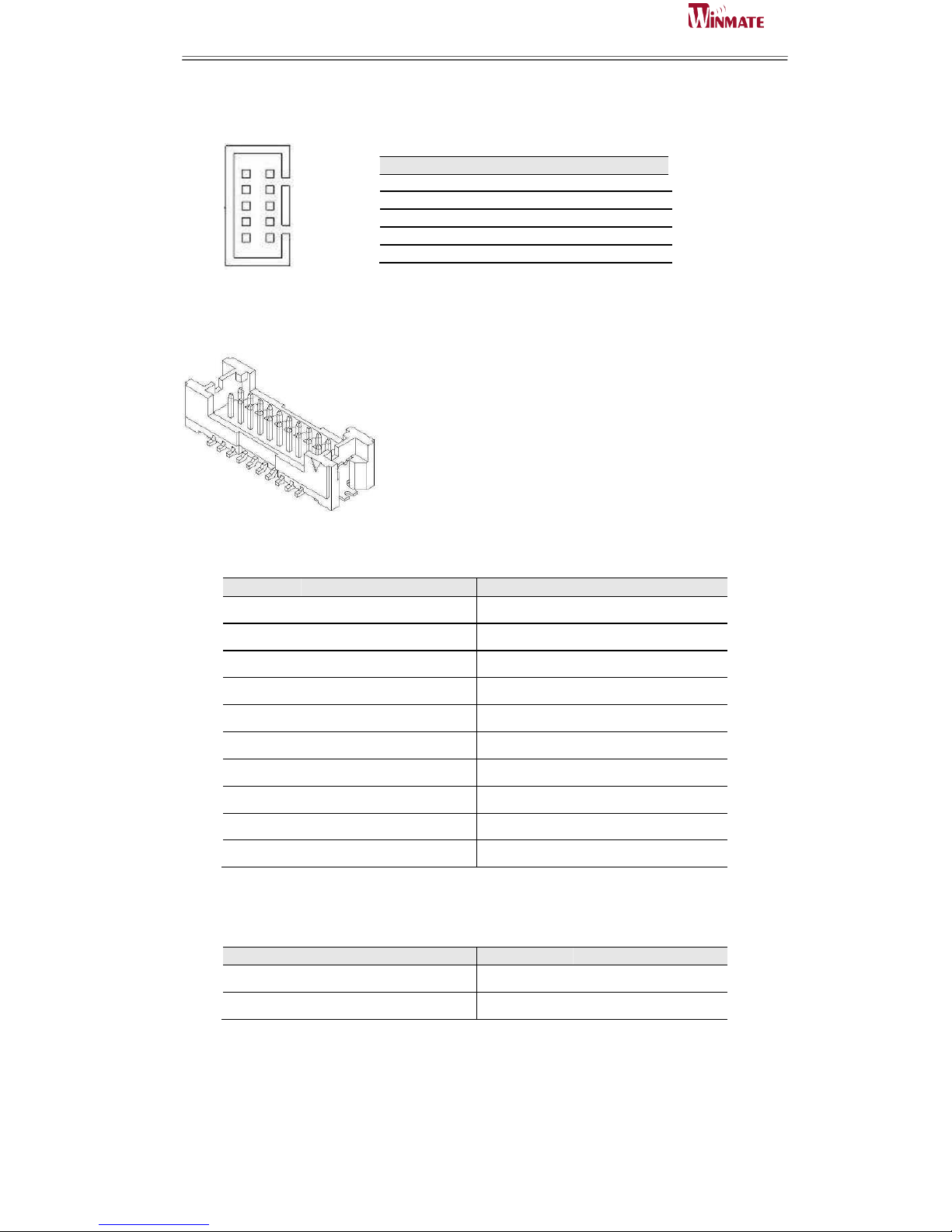
2.5.11 J4/CN27/CN28/CN25: Serial port COM2/COM3/COM4/COM5
10
9
8 7
6 5
4 3
2 1
Pin SYMBOL Pin SYMBOL
10
+5V 9
GND
8 NRI1A 7
NDTR1A
6
NCTS1A
5
NTXD1A
4
NRTS1A
3
NRXD1A
2 NDSR1A
1 NDCD1A
2.5.12 CN23: DVI connector
.
Pin No.
SYMBOL
Pin No.
SYMBOL
1
GND
2
TMDSB_DATA0-
3
GND
4
TMDSB_DATA0+
5
DVIC_LVDS_DET
6
TMDSB_DATA1-
7
DVIC_BKLTEN
8
TMDSB_DATA1+
9
DVIC_VDDEN
10
TMDSB_DATA2-
11
DVI_HOT_DETECT
12
TMDSB_DATA2+
13
LCDVDD
14
TMDSB_BLK-
15
LCDVDD
16
TMDSB_BLK+
17
+V5S
18
DVI1_DDC_CLK_R
19
+V5S
20
DVI_DDC_DAT_R
2.5.13 CN16: SM Bus Connector
Pin No.
SYMBOL
Pin No.
SYMBOL
1
+3.3V
2
MS_DATA
3
MS_CLK
4
GND+
Page 27

ID31 Motherboard User Manual
19
ID31 Motherboard User Manual /
Engineering Spec.
2.5.14 CN11: UART Connector
Pin No.
SYMBOL
Pin No.
SYMBOL
1
+3.3V(default)/5V
2
UART Tx
3
UART Rx
4
UART CTS
5
UART RTS
6
GND
2.5.15 CN9: Mini PCIe slot for SSD
Pin Number
Signal Name
Pin Number
Signal Name
1
NC
2
+V3.3DX_SSD
3
NC
4
GND
5
NC
6
+V1.5S_SSD
7
NC
8
NC
9
GND
10
NC
11
NC
12
NC
13
NC
14
NC
15
GND
16
NC
17
NC
18
GND
19
NC
20
NC
21
GND
22
NC
23
SATA_RXP2
24
+V3.3DX_SSD
25
SATA_RXN2
26
GND
27
GND
28
+V1.5S_SSD
29
GND
30
NC
31
SATA_TXN2
32
NC
33
SATA_TXP2
34
GND
35
GND
36
NC
37
GND
38
NC
39
+V3.3DX_SSD
40
GND
41
+V3.3DX_SSD
42
NC
43
GND
44
SATA2_DEVSLP
45
NC
46
NC
47
NC
48
+V1.5S_SSD
49
SSD_LED#
50
GND
51
+V3.3DX_SSD
52
+V3.3DX_SSD
M1
GND
M1
GND
M2
GND
M2
GND
Page 28

ID31 Motherboard User Manual
20
ID31 Motherboard User Manual /
Engineering Spec.
2.5.16 CN10: Mini PCIe slot for WLAN
Pin Number
Signal Name
Pin Number
Signal Name
1
NC
2
+V3.3DX_SSD
3
NC
4
GND
5
NC
6
+V1.5S_SSD
7
NC
8
NC
9
GND
10
NC
11
NC
12
NC
13
NC
14
NC
15
GND
16
NC
17
NC
18
GND
19
NC
20
NC
21
GND
22
NC
23
SATA_RXP2
24
+V3.3DX_SSD
25
SATA_RXN2
26
GND
27
GND
28
+V1.5S_SSD
29
GND
30
NC
31
SATA_TXN2
32
NC
33
SATA_TXP2
34
GND
35
GND
36
NC
37
GND
38
NC
39
+V3.3DX_SSD
40
GND
41
+V3.3DX_SSD
42
NC
43
GND
44
SATA2_DEVSLP
45
NC
46
NC
47
NC
48
+V1.5S_SSD
49
SSD_LED#
50
GND
51
+V3.3DX_SSD
52
+V3.3DX_SSD
M1
GND
M1
GND
M2
GND
M2
GND
Page 29

ID31 Motherboard User Manual
21
ID31 Motherboard User Manual /
Engineering Spec.
3
Graphic Driver Installation
This chapter offers information on the chipset software
Installation utility
Installation of Graphic Driver
Panel Resolution Setting
C H A P T E R
Page 30
ID31 Motherboard User Manual
22
ID31 Motherboard User Manual /
Engineering Spec.
Chapter 3 Graphic Driver Installation
3.1 Standard CMOS Feature
ID31 Motherboard is equipped with Intel NM10 Companion Device. The Intel
Graphic Drivers should be installed first, and it will enable “Video Controller
(VGA compatible). Follow the instructions below to complete the installation.
You will quickly complete the installation.
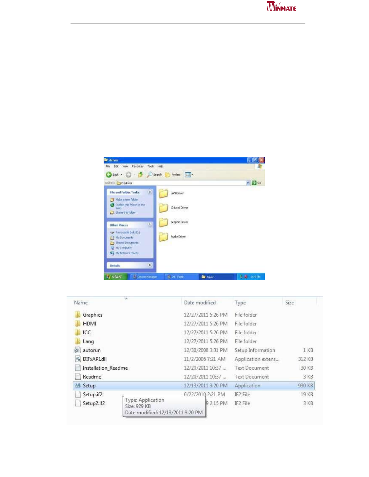
Step.1. Insert the CD that comes with the Motherboard. Open the file
document “Graphic Driver “.
Step.2. Click on “setup” to execute the setup.
Page 31
ID31 Motherboard User Manual
23
ID31 Motherboard User Manual /
Engineering Spec.
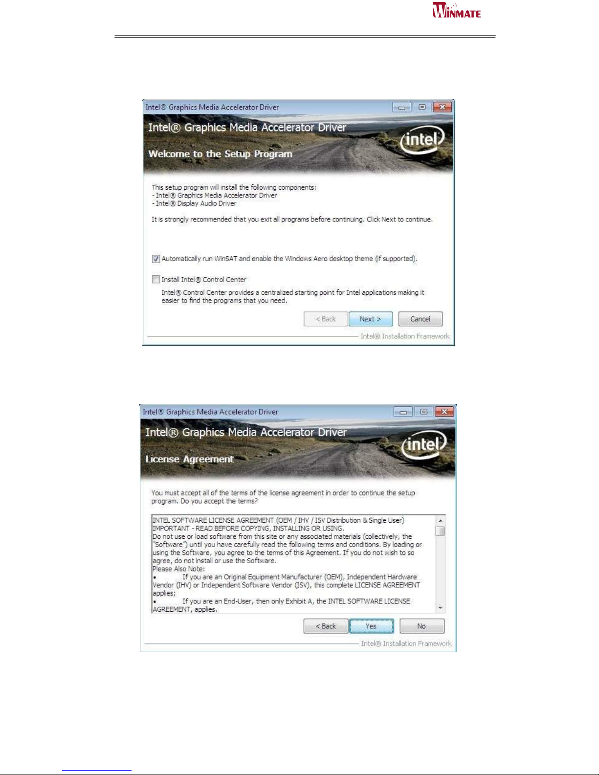
Step.3. Click on “Next “ to install Driver.
Step.4. Click on “Yes “ to agree License.
Page 32
ID31 Motherboard User Manual
24
ID31 Motherboard User Manual /
Engineering Spec.
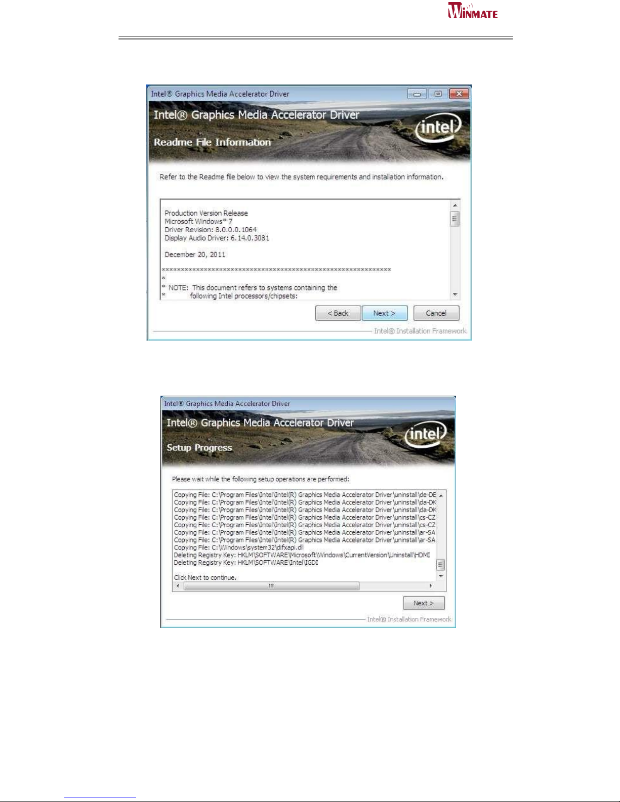
Step.5. Click on “Next “ to install Driver.
Step.6. Click on “Next “ to install Driver.
Page 33
ID31 Motherboard User Manual
25
ID31 Motherboard User Manual /
Engineering Spec.
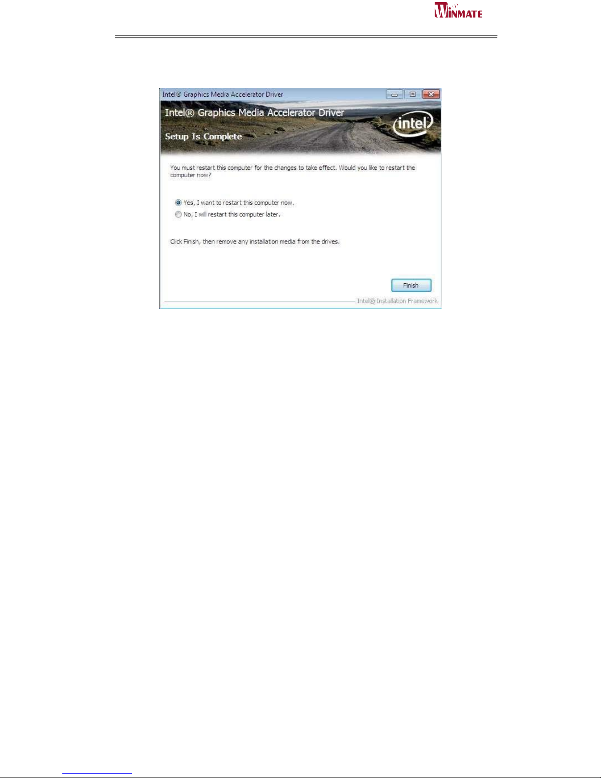
Step.7. Click on “Yes, I want to restart this computer now“ to go on.
Page 34
ID31 Motherboard User Manual
26
ID31 Motherboard User Manual /
Engineering Spec.
3.2 Panel Resolution Setting
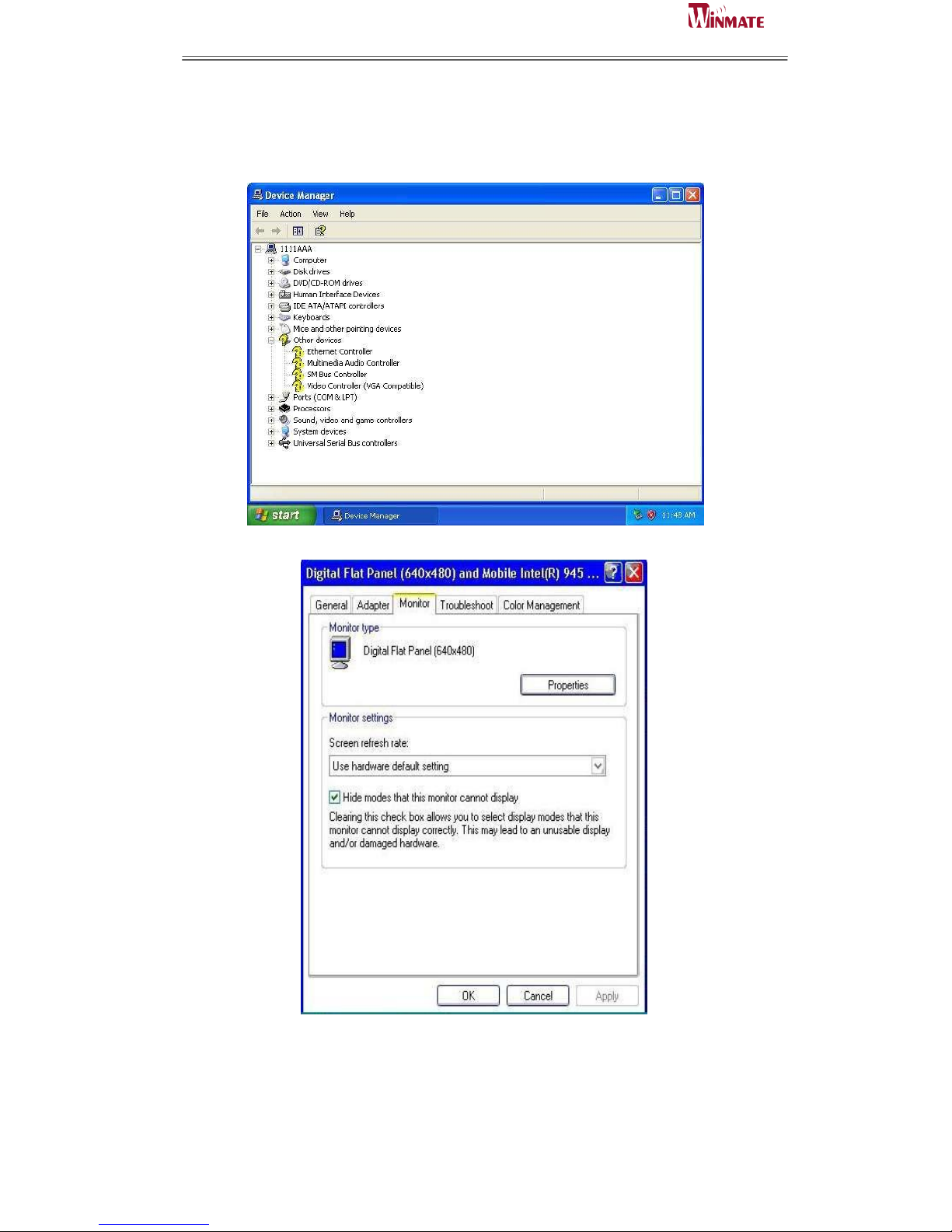
Step.1. Right-click the desktop, and then click Properties.
Step.2. In the Display Properties dialog box, click the Settings tab.
Step.3. Click on “Monitor”.
Page 35
ID31 Motherboard User Manual
27
ID31 Motherboard User Manual /
Engineering Spec.
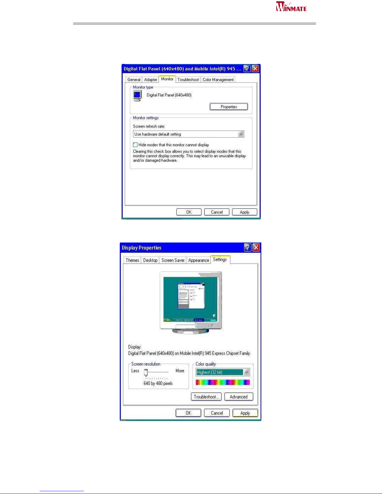
Step.4. Click on “Hide modes that this monitor cannot display” to remove this
option.
Step.5. Click on “Setting”, then could choose 32bit color qualify.
Page 36

ID31 Motherboard User Manual
28
ID31 Motherboard User Manual /
Engineering Spec.
4
Chipset Driver Installation
This chapter offers information on the chipset software
Installation utility
Installation of Chipset Driver
Further information
C H A P T E R
Page 37
ID31 Motherboard User Manual
29
ID31 Motherboard User Manual /
Engineering Spec.
Chapter 4 Chipset Driver Installation
4.1 Standard CMOS Features
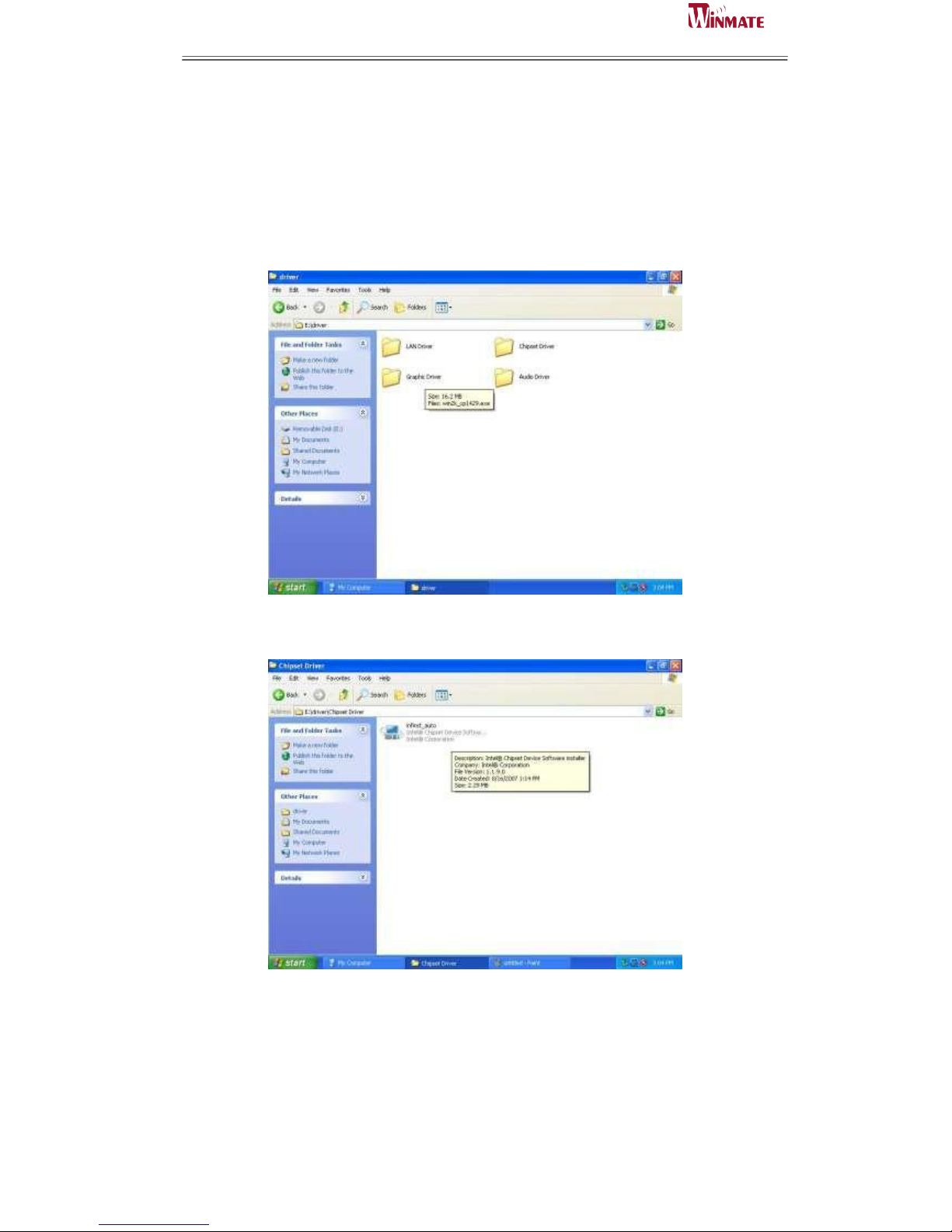
Setp.1. Insert the CD that comes with the motherboard. Open the file document
“Chipset Driver”.
Setp.2. Click on “infinst_auto.exe“ to install driver.
Page 38
ID31 Motherboard User Manual
30
ID31 Motherboard User Manual /
Engineering Spec.
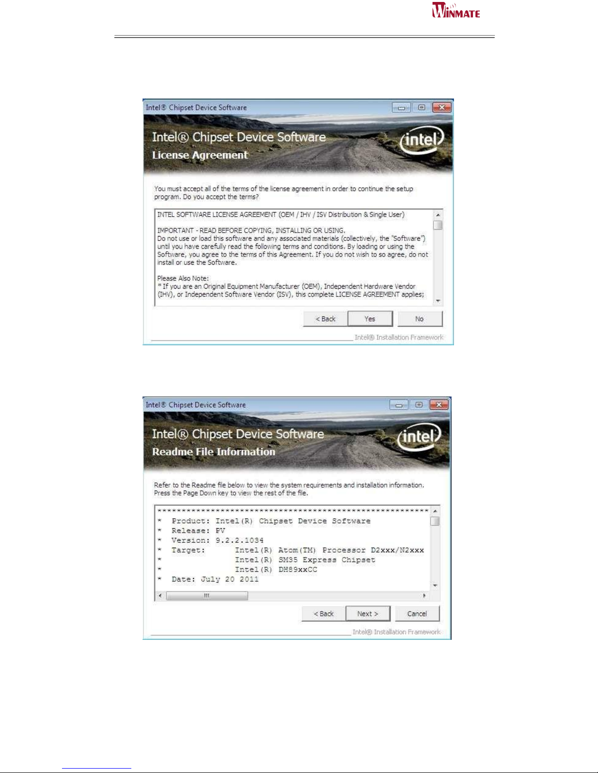
Setp.3. Click on “Yes “ to agree License
Setp.4. Click on “Next“ to install driver.
Page 39
ID31 Motherboard User Manual
31
ID31 Motherboard User Manual /
Engineering Spec.
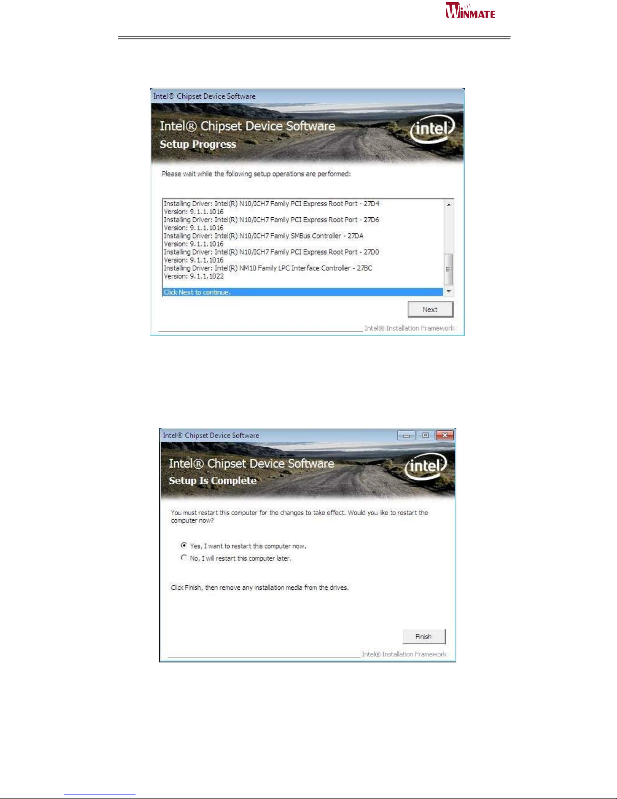
Setp.5. Click on “Next“ to install driver.
Step.7. Click on “Yes, I want to restart this computer now“ to go on.
Page 40

ID31 Motherboard User Manual
32
ID31 Motherboard User Manual /
Engineering Spec.
5
Ethernet Driver Installation
This chapter offers information on the Ethernet software
installation utility.
Sections include:
Introduction
Installation of Ethernet Driver
C H A P T E R
Page 41
ID31 Motherboard User Manual
33
ID31 Motherboard User Manual /
Engineering Spec.
Chapter 5 Ethernet Driver Installation
Installation of Ethernet Driver
The Users must make sure which operating system you are using in the ID31
Motherboard before installing the Ethernet drivers. Follow the steps below to
complete the installation of the Broadcom BCM57780 Gigabit Ethernet controller
LAN drivers. You will quickly complete the installation.
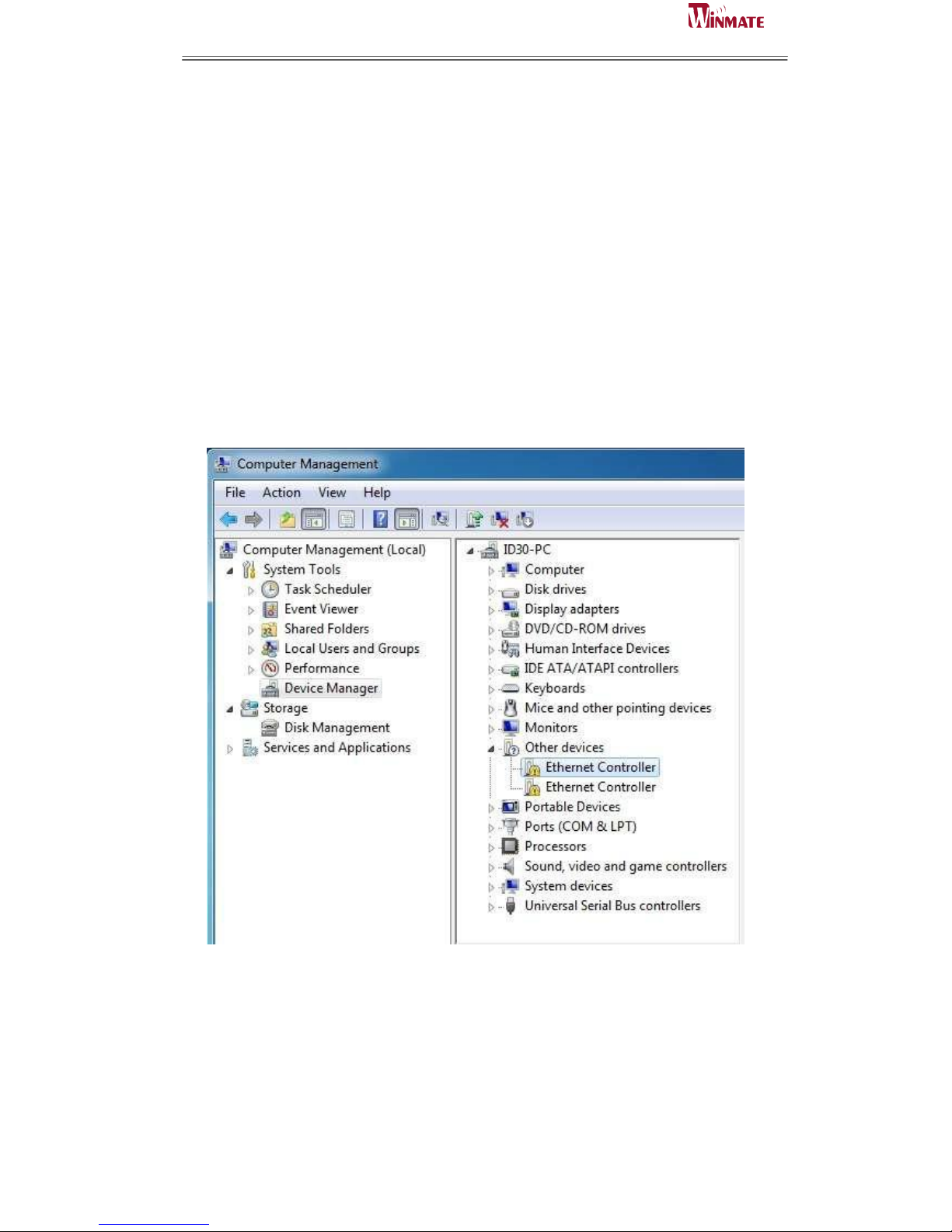
Step.1. Right-click the desktop, and then click Properties.
Step.2. In the Other device dialog box, click the Settings tab.
Page 42
ID31 Motherboard User Manual
34
ID31 Motherboard User Manual /
Engineering Spec.
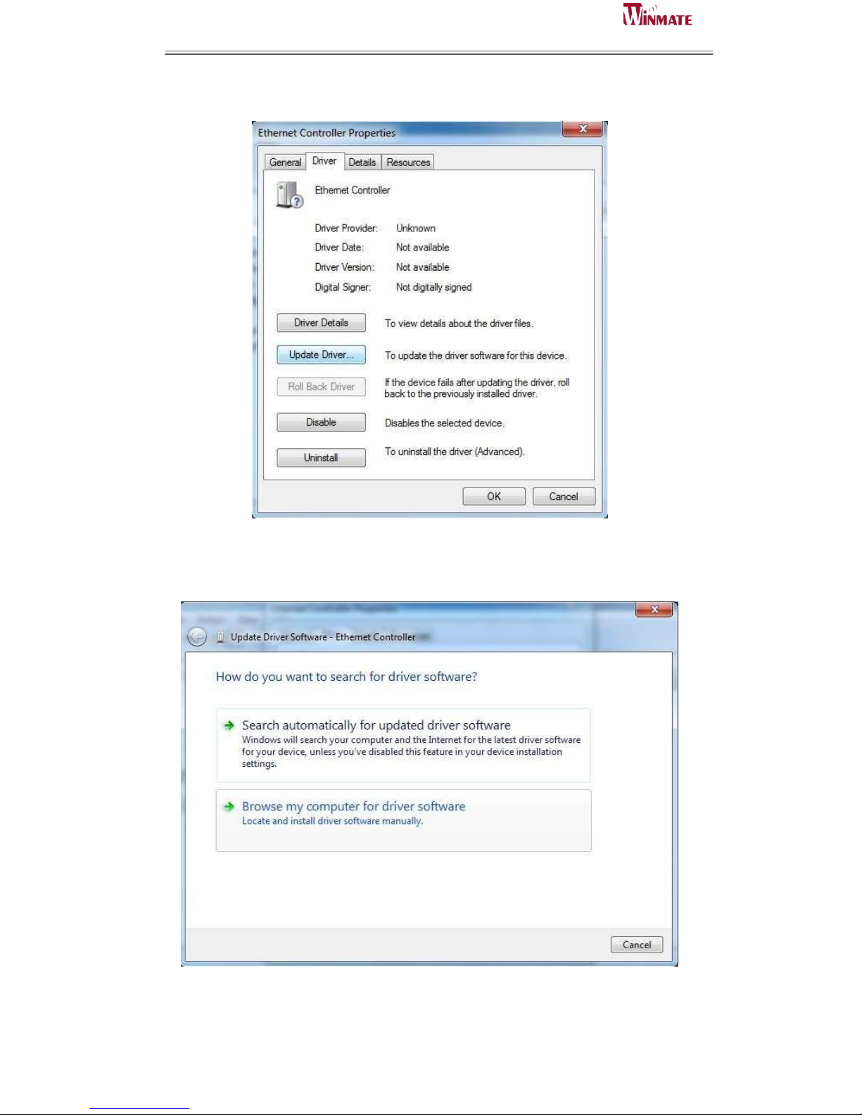
Step.2 Click on “Update Driver” to execute the setup.
Step.4. Click on “Browse my computer for driver software“ to install driver.
Page 43
ID31 Motherboard User Manual
35
ID31 Motherboard User Manual /
Engineering Spec.
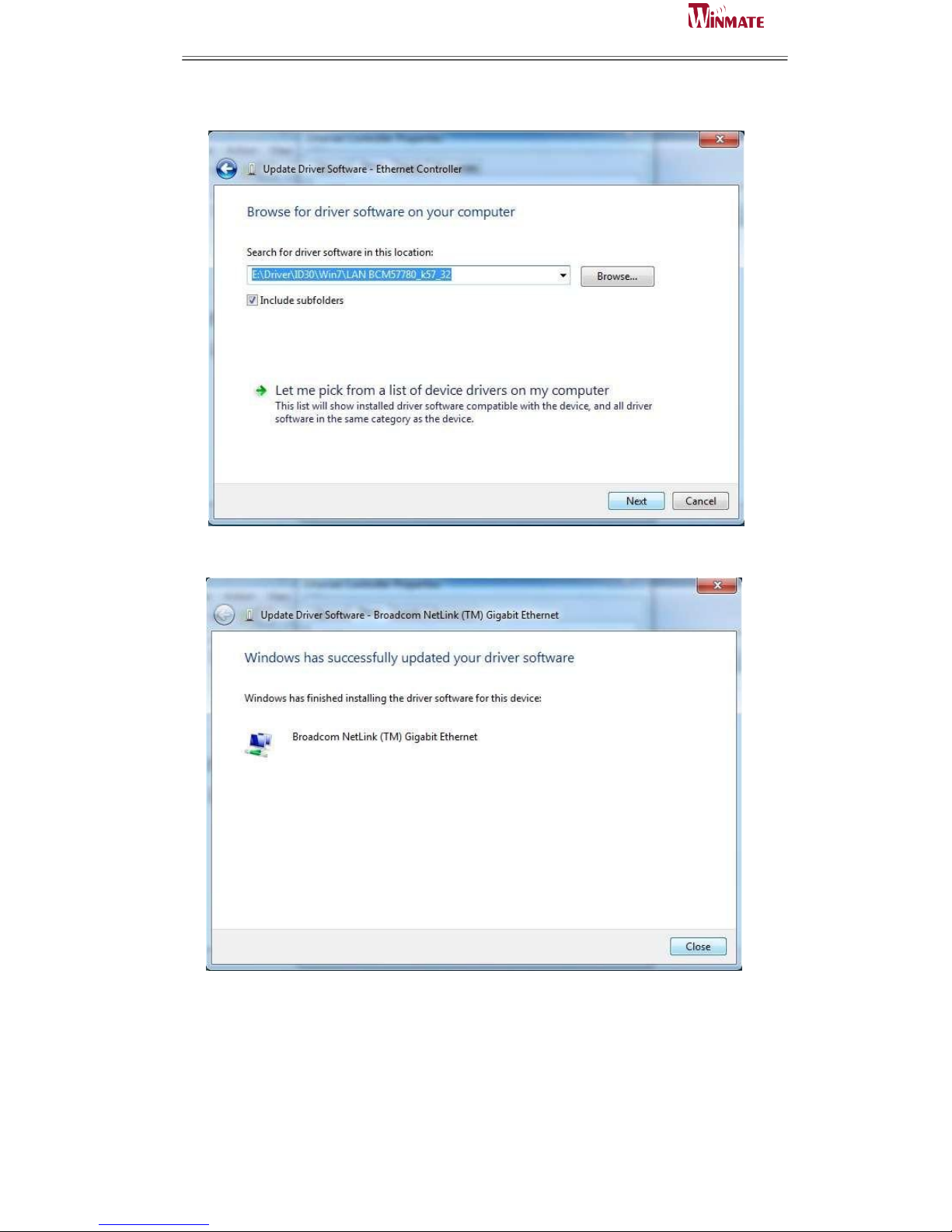
Step.5. Choose the path to install driver.
Setp.6. Click on “Close“ and go on.
Page 44

ID31 Motherboard User Manual
36
ID31 Motherboard User Manual /
Engineering Spec.
6
Audio Driver Installation
This chapter offers information on the Audio software
installation utility.
Sections include:
Introduction
Installation of Audio Driver
C H A P T E R
Page 45
ID31 Motherboard User Manual
37
ID31 Motherboard User Manual /
Engineering Spec.
Chapter 6 Audio Driver Installation
6.1 Introduction
The ALC888 series are high-performance 7.1+2 Channel High Definition Audio
Codecs providing ten DAC channels that simultaneously support 7.1 sound playback,
plus 2 channels of independent stereo sound output (multiple streaming) through the
front panel stereo outputs. The series integrates two stereo ADCs that can support a
stereo microphone, and feature Acoustic Echo Cancellation (AEC), Beam Forming
(BF), and Noise Suppression (NS) technology.
6.2 Installation of Audio Driver
The users must make sure which operating system you are using in the IA30
Motherboard before installing the Audio drivers. Follow the steps below to complete
the installation of the Realtek ALC655 Audio drivers. You will quickly complete the
installation.
Step.1. Insert the CD that comes with the motherboard. Open the file document
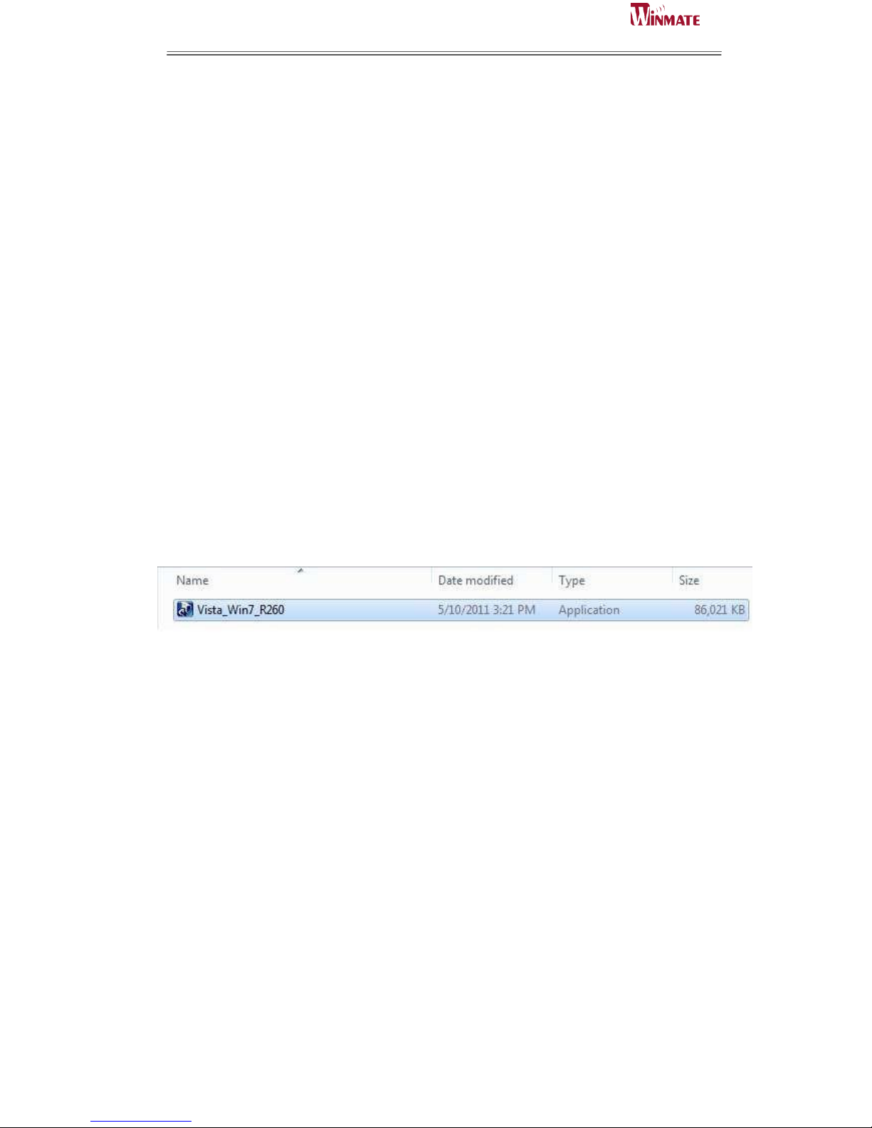
“alc655_driver” and click on “Vista_Win7_R260.exe” to execute the setup.
Page 46
ID31 Motherboard User Manual
38
ID31 Motherboard User Manual /
Engineering Spec.
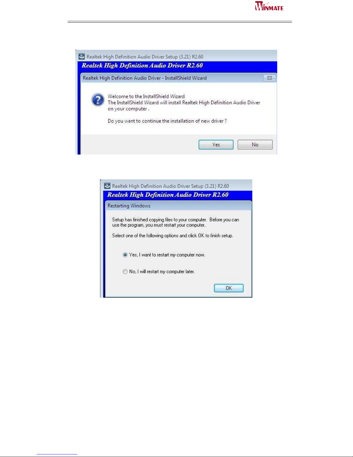
Step.2. Click on “Yes“ to install driver.
Step.3. Click on “Yes, I want to restart my computer now” to finish installation.
Page 47

ID31 Motherboard User Manual
39
ID31 Motherboard User Manual /
Engineering Spec.
7
Fintek COM Port
Driver Installation
This chapter describes the step by step
method to install the Fintek COM port driver.
C H A P T E R
Page 48
ID31 Motherboard User Manual
40
ID31 Motherboard User Manual /
Engineering Spec.
STEP 1.If the system is WIN7 please first do close UAC.(Refer following “Disabling
User Account
Control (UAC) in Windows 7”)
STEP 2.Extract the Patch_0408.zip to a folder.
STEP 3.Double-click batch file(patch.bat) will install driver.
STEP 4.Check driver install success.
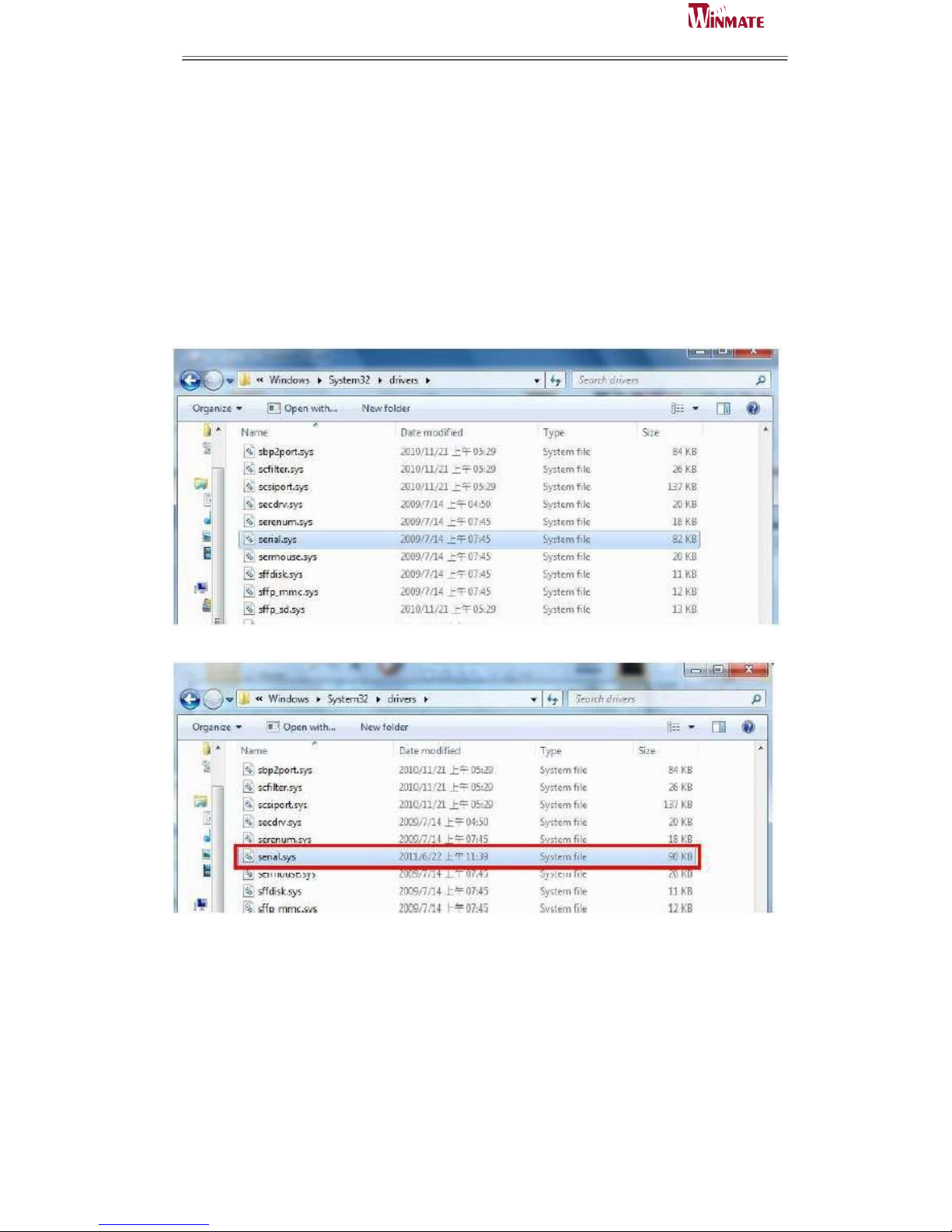
Before the update or update fail.
After the update and update success.
STEP 5.You will need to restart your computer for driver install success.
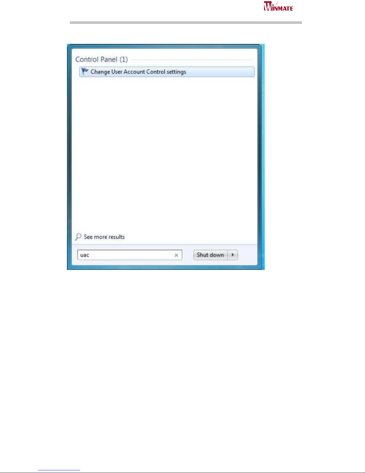
Type in this command from the Run menu:
C:\Windows\System32\UserAccountControlSettings.exe
or
uac
Page 49
ID31 Motherboard User Manual
41
ID31 Motherboard User Manual /
Engineering Spec.
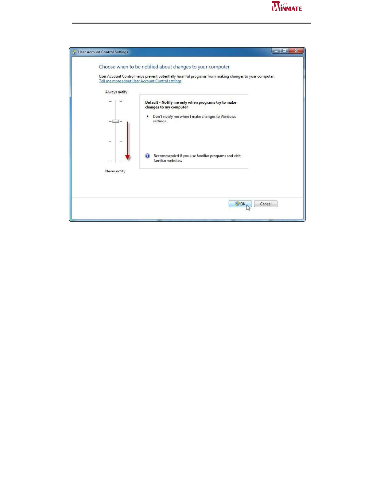
To turn off UAC, move the slider to the Never notify position, and then click OK. If
you're prompted for an administrator password or confirmation, type the password or
provide confirmation.
Page 50
ID31 Motherboard User Manual
42
ID31 Motherboard User Manual /
Engineering Spec.
To turn UAC back on, move the slider to choose when you want to be notified, and
then click OK. If
you're prompted for an administrator password or confirmation, type the password or
provide
confirmation.
You will need to restart your computer for UAC to be turned off.
Page 51

ID31 Motherboard User Manual
43
ID31 Motherboard User Manual /
Engineering Spec.
8
AMI BIOS Setup
This chapter describes how to set up the
BIOS configuration
C H A P T E R
Page 52
ID31 Motherboard User Manual
44
ID31 Motherboard User Manual /
Engineering Spec.
Chapter 7 AMI BIOS SETUP
Your computer comes with a hardware configuration program which called BIOS
Setup that allows you to view and set up the system parameters.
The BIOS (Basic Input / Output System) is a layer of the software called ‘firmware’
which translates instructions from software (such as the operating system) into
instructions that allow the computer hardware to understand the software programs.
The BIOS settings also identify installed devices and establish many special features.
ENTERING BIOS SETUP
You can access the BIOS program just after you turn on your computer. Just press the
“DEL” key when the following prompt appears:
Press <DEL> to enter Setup.
When you press <DEL> to enter the BIOS Setup image, the system interrupts the
Power-On Self-Test (POST).
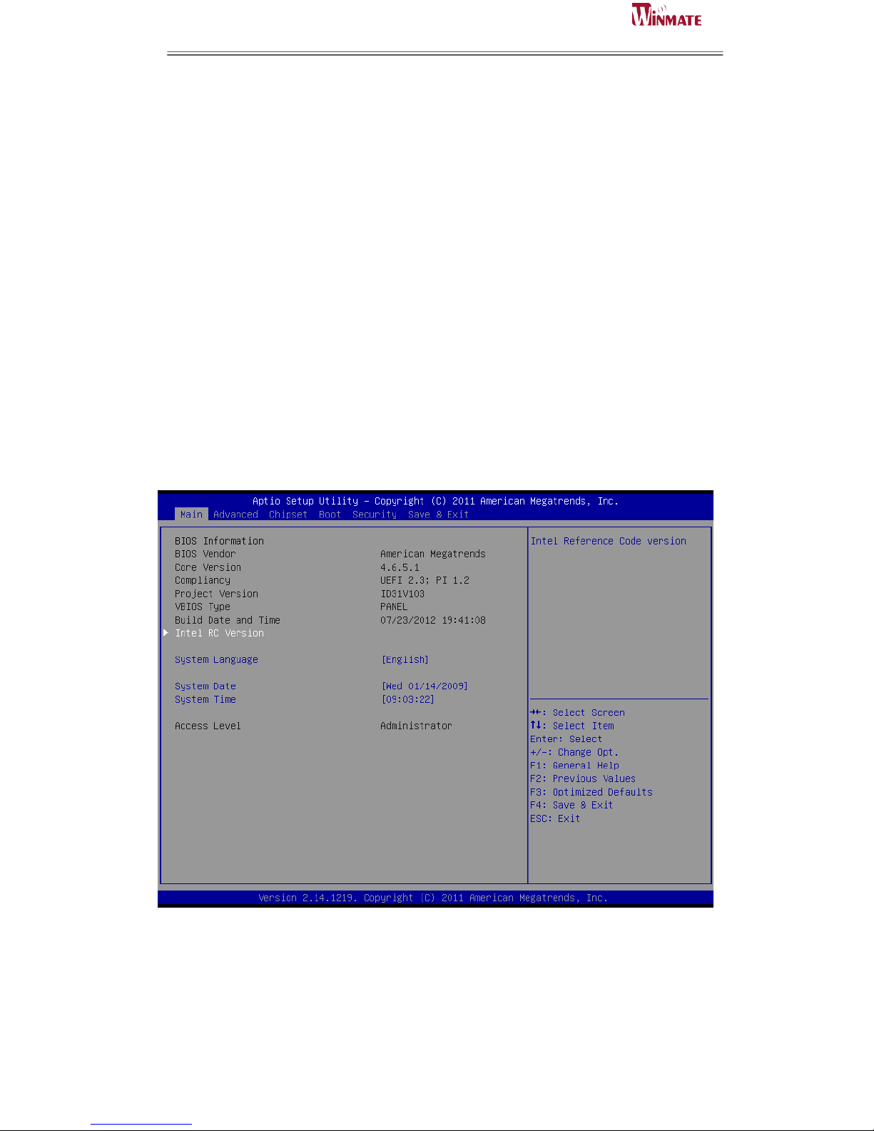
When you first enter the BIOS Setup Utility, you will enter the Main setup image. You
can always return to the Main setup image by selecting the Main tab. There are two
Main Setup options. They are described in this section. The Main BIOS Setup image
is shown as below.
Page 53
ID31 Motherboard User Manual
45
ID31 Motherboard User Manual /
Engineering Spec.
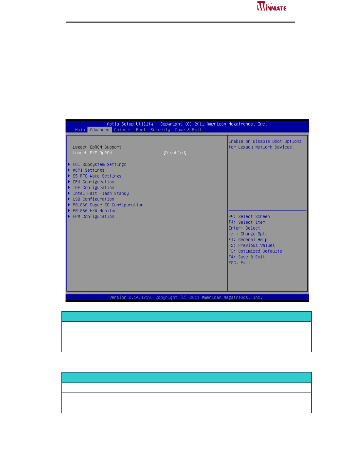
The Main BIOS setup image has two main frames. The left frame displays all the
options that can be configured. Grayed-out options cannot be configured. On the
contrary, options in blue can be configured. The right frame displays the key legend.
Above the key legend is an area reserved for a text message. When an option is
selected in the left frame, it is highlighted in white. Often a text message will
accompany it.
7.1 Advanced Setting
Launch PXE OpROM
SETTING
DESCRIPTION
Disabled
Use this setting to ignore all PXE Option ROMs.
Enabled
Use this setting to load PXE Option ROMs. To limit the PXE support to particular devices, use
the function Use device for PXE.
Default: Disabled
Launch Storage OpROM
SETTING
DESCRIPTION
Disabled
Use this setting to ignore all Storage Option ROMs.
Enabled
Use this setting to load Storage Option ROMs. To limit the Storage support to particular
devices, use the function Use device for Storage.
Default: Disabled
Page 54
ID31 Motherboard User Manual
46
ID31 Motherboard User Manual /
Engineering Spec.
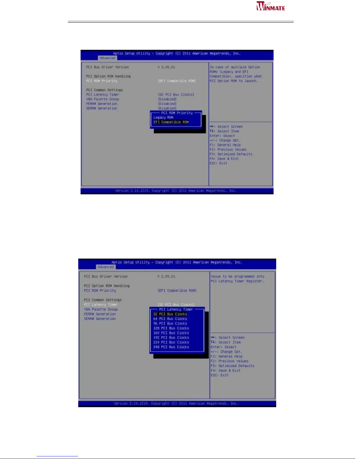
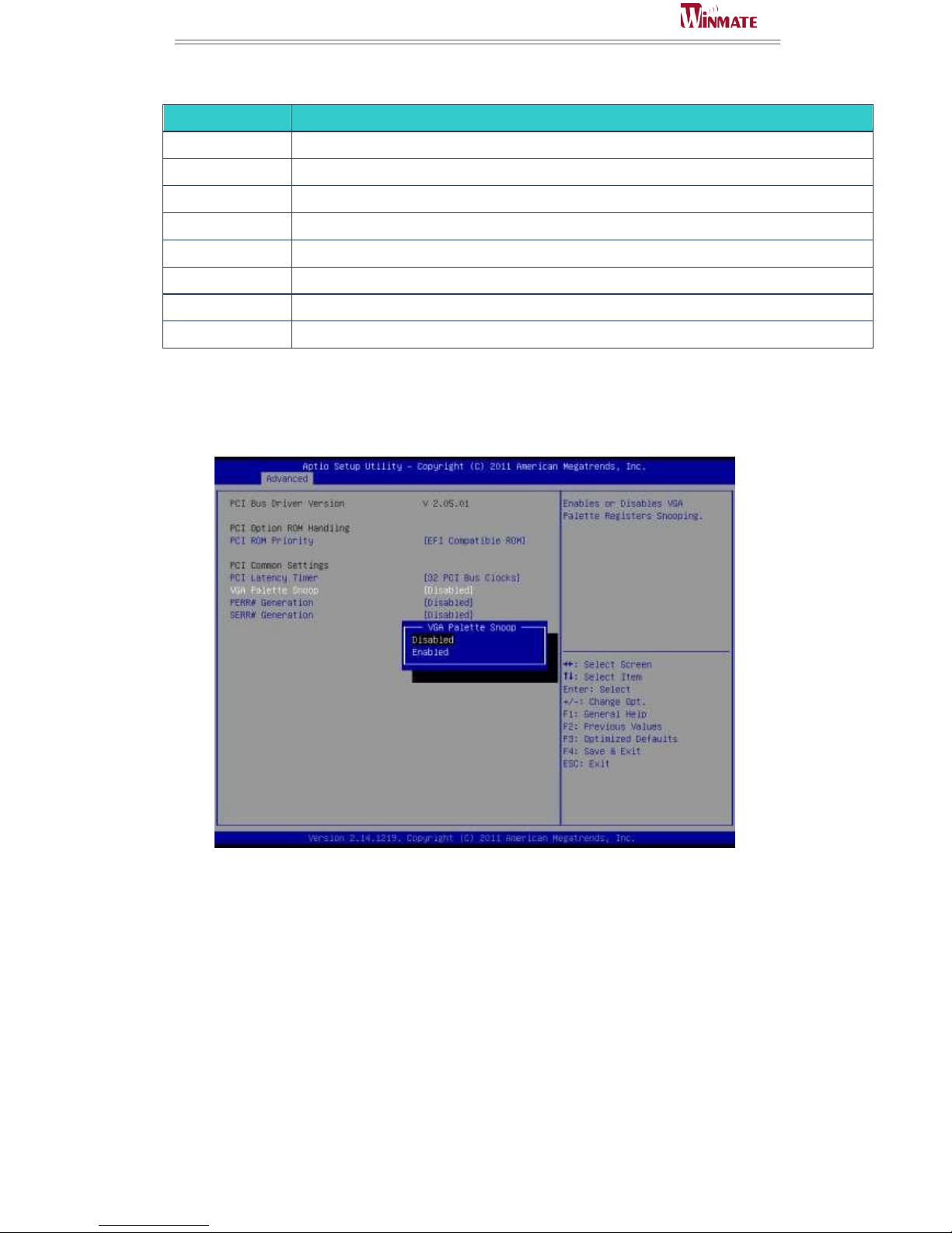
PCI ROM Priority
Selects the PCI Option ROM to launch in case Multiple Option ROMs (Legacy ROM
and EFI Compatible ROM) are present.
PCI Latency Timer
Use this function to select the number of PCI bus clocks to be used for the PCI
latency timer.
Page 55
ID31 Motherboard User Manual
47
ID31 Motherboard User Manual /
Engineering Spec.
SETTING
DESCRIPTION
32 PCI Bus Clocks
Use this setting to program the PCI latency timer to 32 PCI bus clocks.
64 PCI Bus Clocks
Use this setting to program the PCI latency timer to 64 PCI bus clocks.
96 PCI Bus Clocks
Use this setting to program the PCI latency timer to 96 PCI bus clocks.
128 PCI Bus Clocks
Use this setting to program the PCI latency timer to 128 PCI bus clocks.
160 PCI Bus Clocks
Use this setting to program the PCI latency timer to 160 PCI bus clocks.
192 PCI Bus Clocks
Use this setting to program the PCI latency timer to 192 PCI bus clocks.
224 PCI Bus Clocks
Use this setting to program the PCI latency timer to 224 PCI bus clocks.
248 PCI Bus Clocks
Use this setting to program the PCI latency timer to 248 PCI bus clocks.
Default: 32 PCI Bus Clocks
VGA Palette Snoop
This filed controls the ability of a primary PCI VGA controller to share a
common palette (when a snoop write cycles) with an ISA video card.
Enables or Disables VGA Palette Registers Snooping.
Default:
Disabled
PERR# Generation
Enables or Disables PCI Device to Generate PERR#.
Default:
Disabled
SERR# Generation
Enables or Disables PCI Device to Generate SERR#.
Default:
Disabled
Page 56
ID31 Motherboard User Manual
48
ID31 Motherboard User Manual /
Engineering Spec.
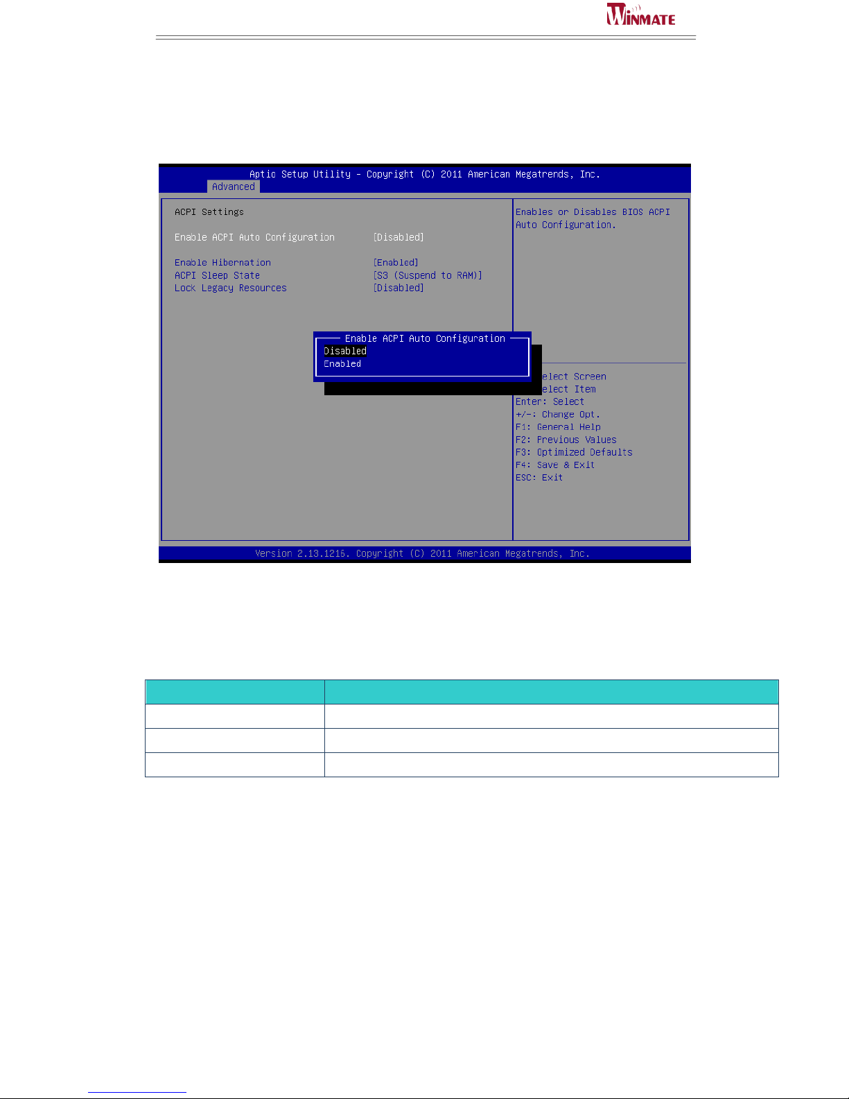
ACPI Settings
Enable ACPI Auto Configuration
Enables or Disables BIOS ACPI Auto Configuration
Default: Disabled
Enable Hibernation
Enables or Disables System ability to Hibernate. This option may be not effective
with some OS.
ACPI Sleep State
SETTING
DESCRIPTION
Suspend Disable
System ability to Hibernate (OS/S3 Sleep State)
S1
CPU Stop Clock
S3
Suspend to RAM
Default: S3 (Suspend to RAM)
Lock Legacy Resources
Enables or Disable Lock of Legacy Resource.
Default: Disable
Page 57
ID31 Motherboard User Manual
49
ID31 Motherboard User Manual /
Engineering Spec.
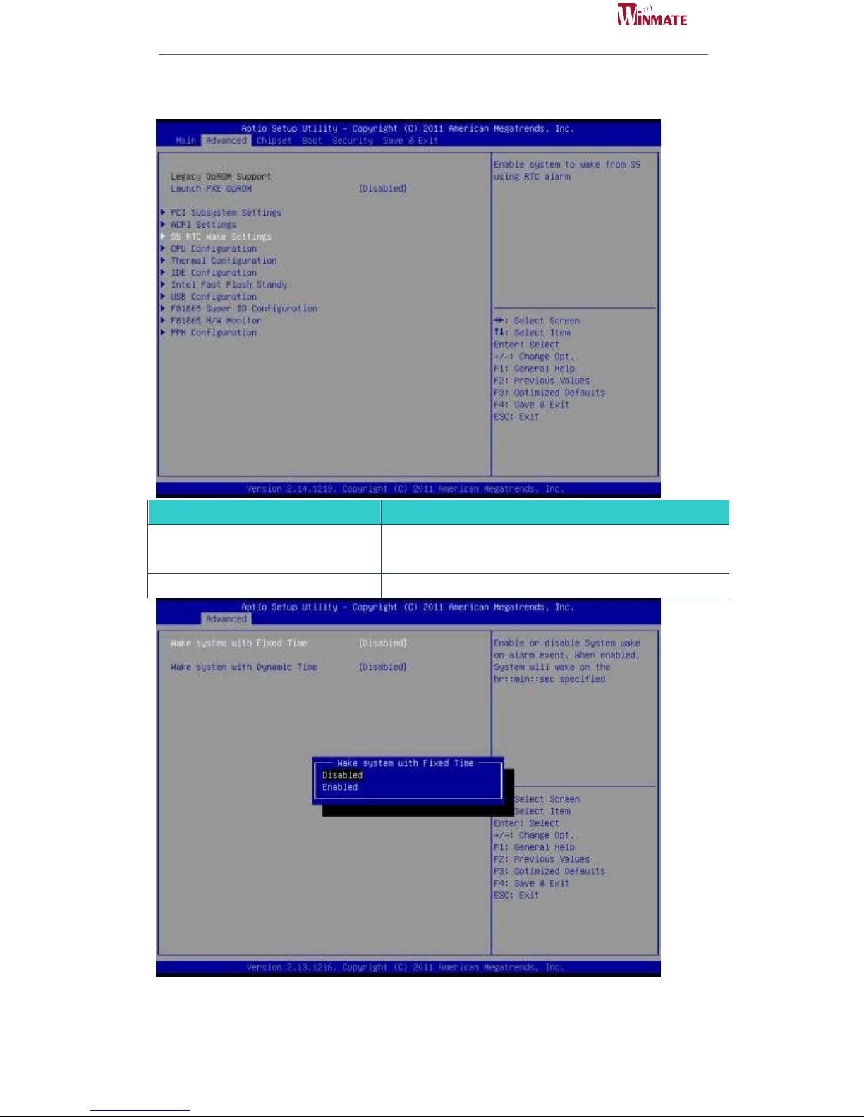
S5 RTC Wake Settings
SETTING
DESCRIPTION
Wake system with Fixed Time
System wake on alarm event. When enabled, System will
wake on the hr: min:: sec specified.
Wake system with Dynamic Time
Options: Enabled, Disabled
Page 58
ID31 Motherboard User Manual
50
ID31 Motherboard User Manual /
Engineering Spec.
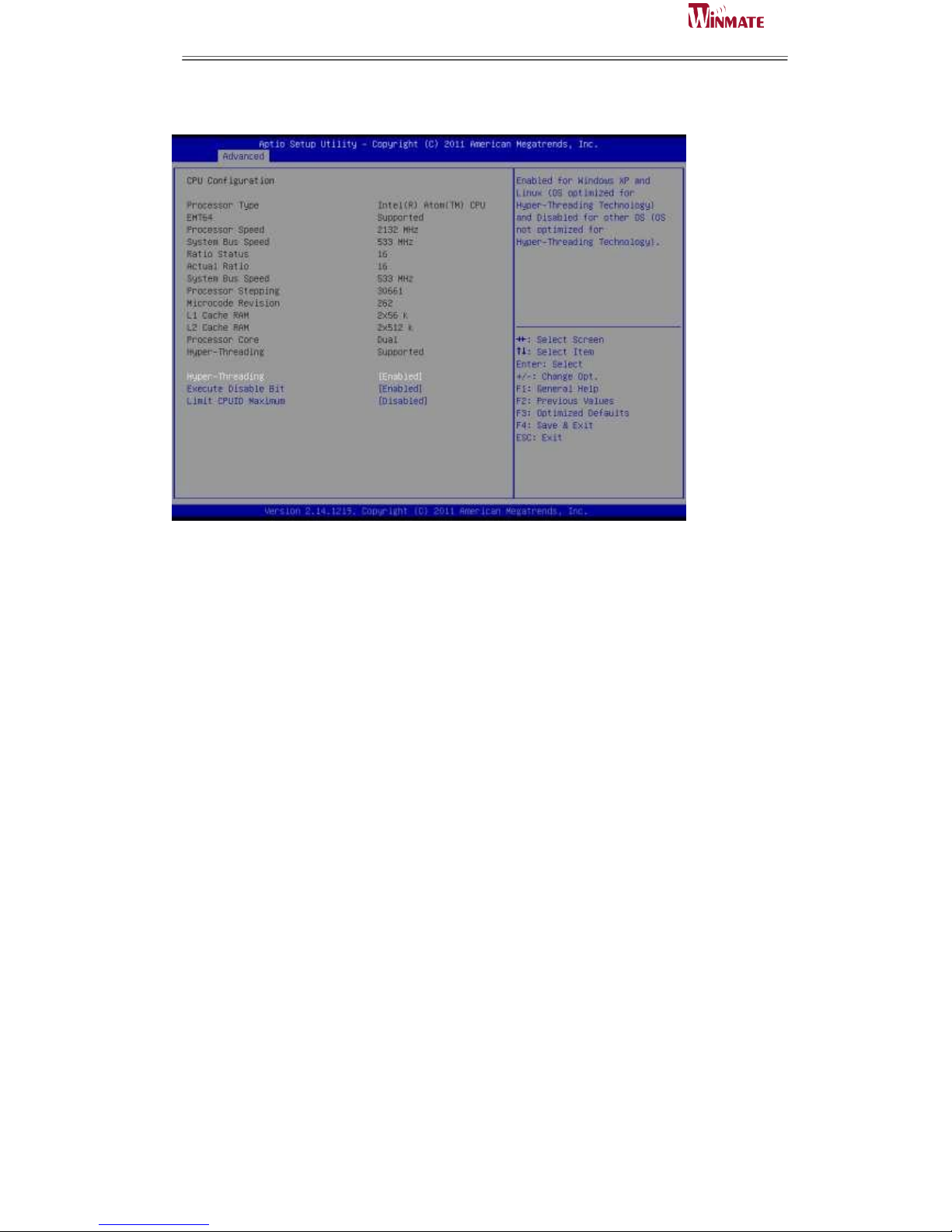
CPU Configuration
Hyper-threading
Enabled for Windows XP and Linux (OS optimized for Hyper-Threading Technology)
and Disabled for other OS (OS not optimized for Hyper-Threading Technology).
When Disabled, only one thread per enabled core is enabled.
Execute Disable Bit
XD can prevent certain classes of malicious buffer overflow attacks when combined
with a supporting OS (Windows Server 2003 SP1, Windows XP SP2, SuSE Linux 9.2,
RedHat Enterprise 3 Update 3.)
Limit CPUID Maximum
Disabled for Windows XP
Page 59
ID31 Motherboard User Manual
51
ID31 Motherboard User Manual /
Engineering Spec.
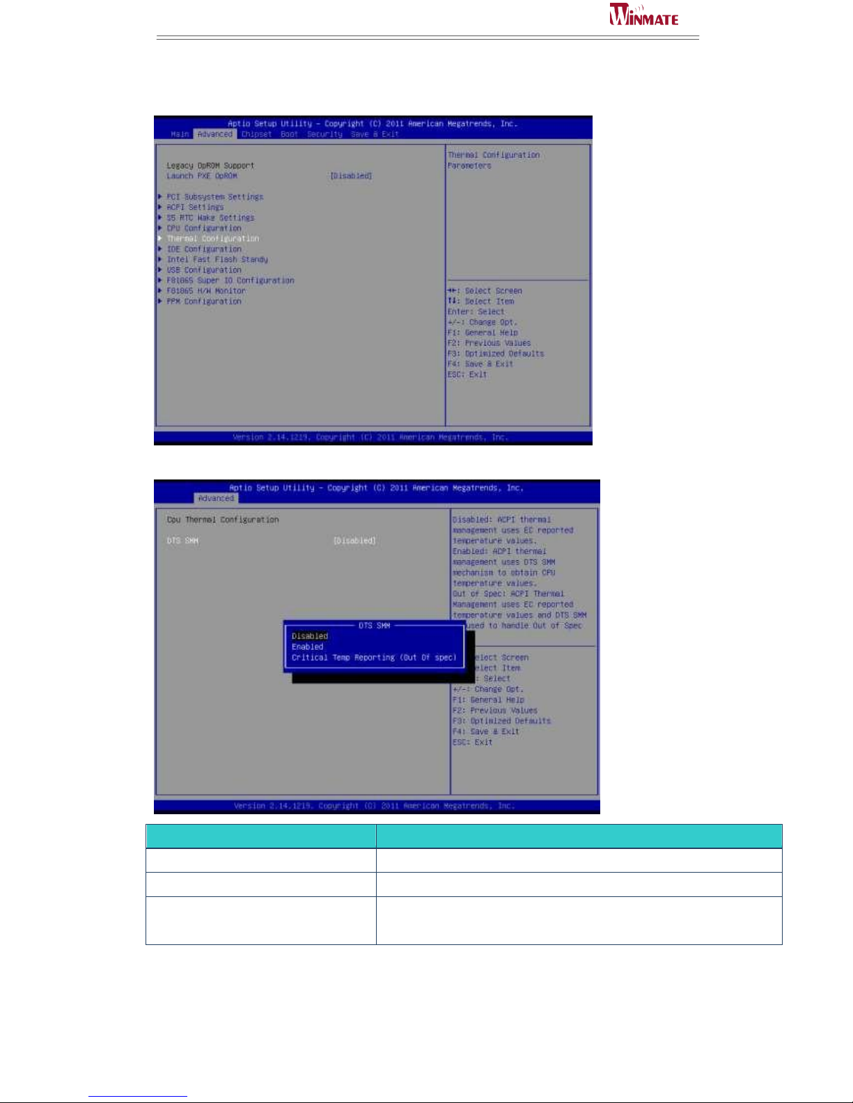
Thermal Configuration
CPU Thermal Configuration > DTS SMM
SETTING
DESCRIPTION
Disabled
Uses EC reported temperature values
Enabled
Uses DTS SMM mechanism to obtain CPU temperature value
Critical Temp Reporting(Out of spec)
Uses EC reported temperature values and DTS SMM to handle out of
spec
Page 60
ID31 Motherboard User Manual
52
ID31 Motherboard User Manual /
Engineering Spec.
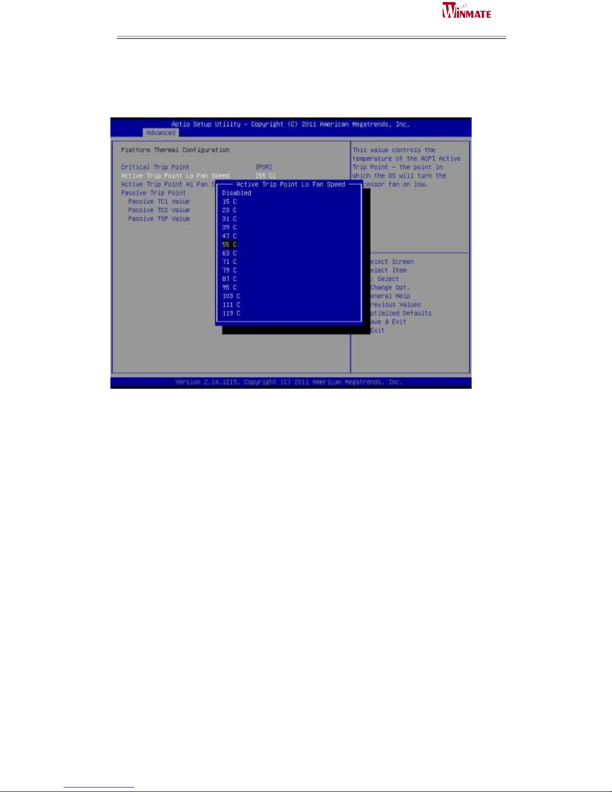
Critical Trip Point
This value controls the temperature of the ACPI critical Trip point—the point in
which the OS will shut the system off.
Active Trip Point Lo Fan Speed
Active Trip Point Hi Fan Speed
This field enables or disables the smart fan feature. At a certain temperature, the fan
starts turning. Once the temperature drops to a certain level, it stops turning again.
Passive TC1 Value
Passive TC2 Value
Passive TSP Value
Page 61
ID31 Motherboard User Manual
53
ID31 Motherboard User Manual /
Engineering Spec.
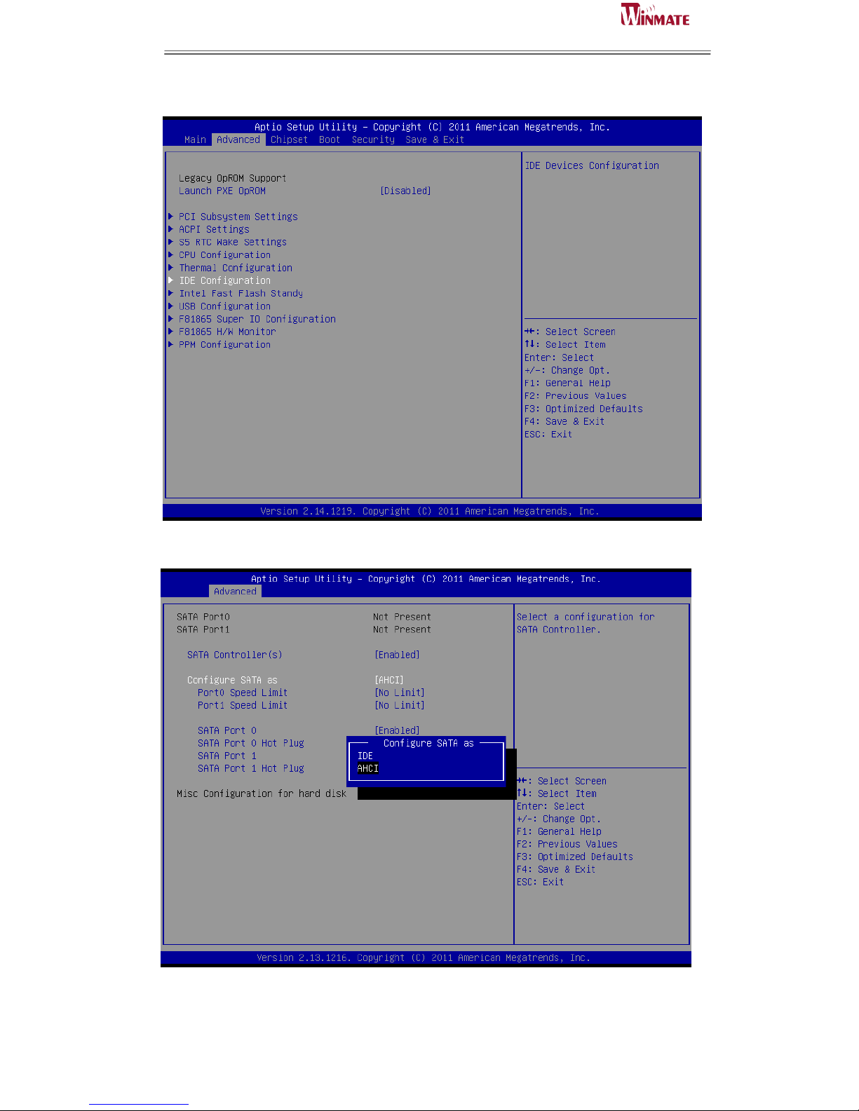
IDE Configuration
Configure SATA as
Determines how SATA controllers(s) operate. The options are IDE and AHCI.
Page 62
ID31 Motherboard User Manual
54
ID31 Motherboard User Manual /
Engineering Spec.
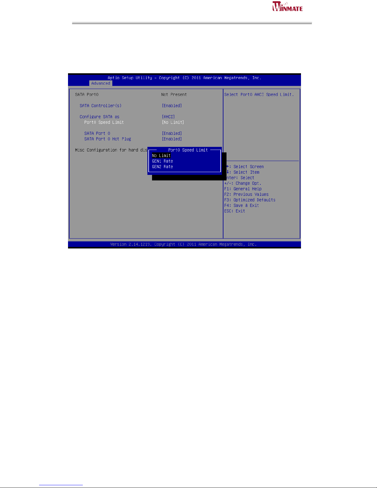
Port0 Speed Limit
Select Port0 AHCI Speed Limit. The options are No Limit, GEN1 Rate and GEN2
Rate.
SATA Port 0/1
Enable or disable SATA Port.
SATA Port 0/1 Hot Plug
Designates this port as Hot Pluggable
.
Page 63
ID31 Motherboard User Manual
55
ID31 Motherboard User Manual /
Engineering Spec.
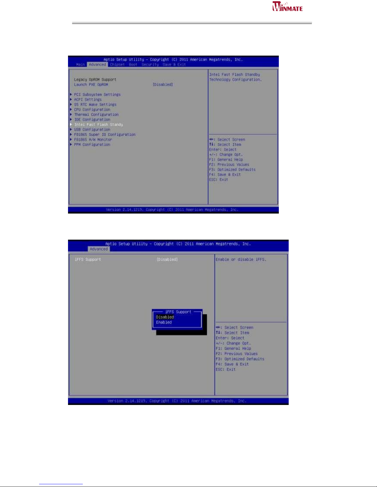
Intel Fast Flash Standy
iFFS Support
Enable or disable
Page 64
ID31 Motherboard User Manual
56
ID31 Motherboard User Manual /
Engineering Spec.
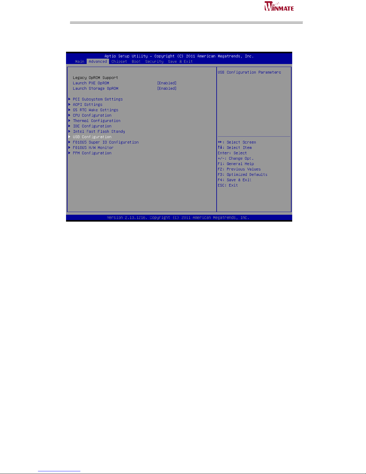
USB Configuration
Legacy USB support
Enables Legacy USB support. AUTO option disable legacy support if no USB devices
are connected. DISABLE option will keep USB devices available only for EFI
applications.
ECHI Hand-off
This is a workaround for OSes without EHCI hand-off support. The EHCI ownership
change should be claimed by EHCI driver.
Default: Disabled
USB transfer time-out
The time-out value for control, bulk, and Interrupt transfers.
Default: 20 sec
Device reset time-out
The USB mass storage device Start Unit command time-out.
Default: 20 sec
Device power-up delay
Maximun time the device will take before it properly reports itself to the Host
Controller. ’Auto’ uses default value: for a Root port it is 100 ms, for a Hub port the
delay is taken from Hub descriptor.
Page 65
ID31 Motherboard User Manual
57
ID31 Motherboard User Manual /
Engineering Spec.
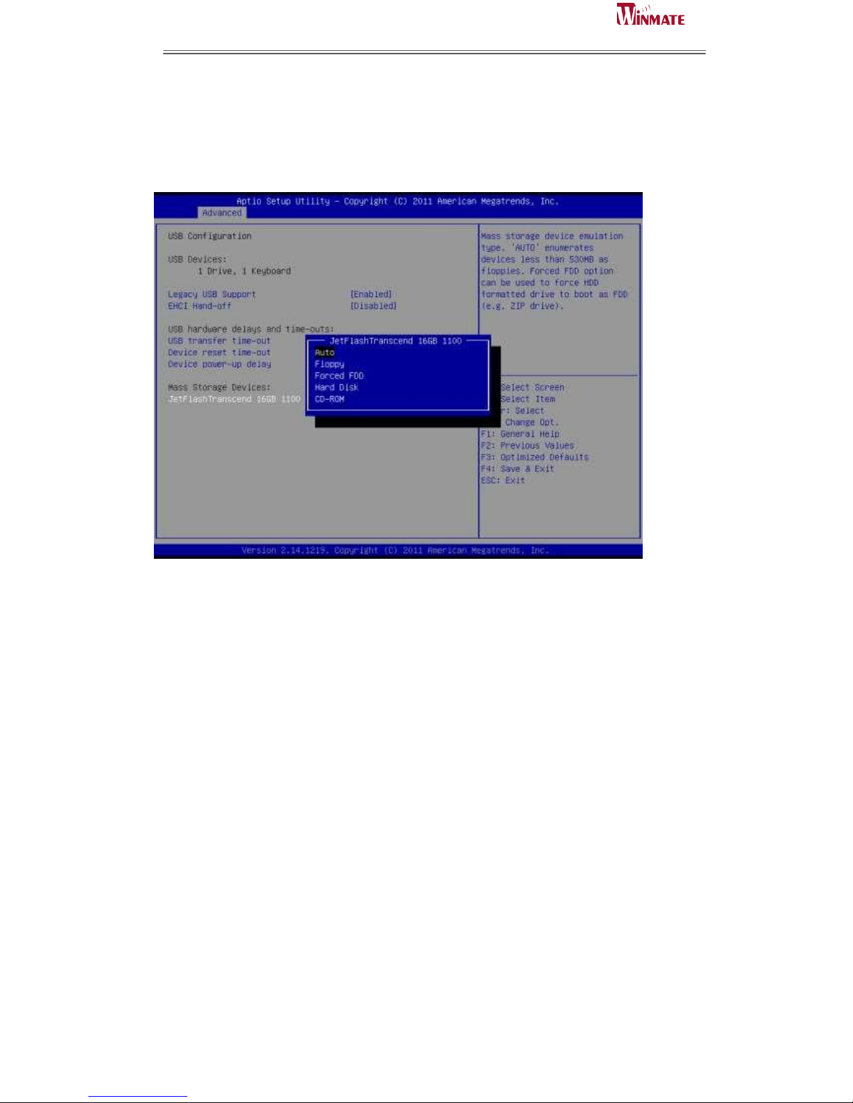
Mass Storage Device:
Mass storage device emulation type. ‘AUTO’ enumerates devices less than 530MB as
floppies. Forced FDD option can be used to force HDD formatted drive to boot as
FDD.
Page 66
ID31 Motherboard User Manual
58
ID31 Motherboard User Manual /
Engineering Spec.
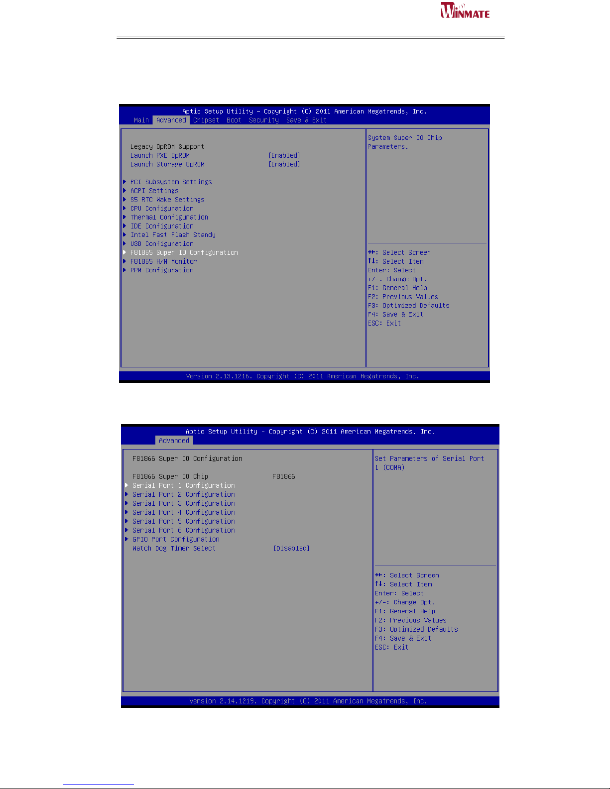
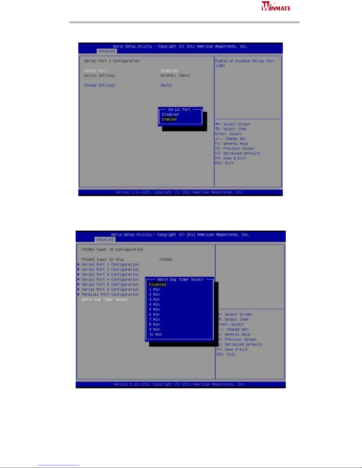
F81865 Super IO Configuration
System Super IO Chip Parameters.
Serial Port 1、2、3 、4、5、6 Configuration
Page 67
ID31 Motherboard User Manual
59
ID31 Motherboard User Manual /
Engineering Spec.
Set Parameters of Serial Ports. User can Enable/Disable the serial port and Select an
optimal settings for the Super IO Device. Enable or Disable Serial Port (COM)
Default: Enable
The watchdog timer circuit has to be triggered within a specified time by the
application software. If the watchdog is not triggered because proper software
execution fails or a hardware malfunction occurs, it will reset the system
Page 68
ID31 Motherboard User Manual
60
ID31 Motherboard User Manual /
Engineering Spec.
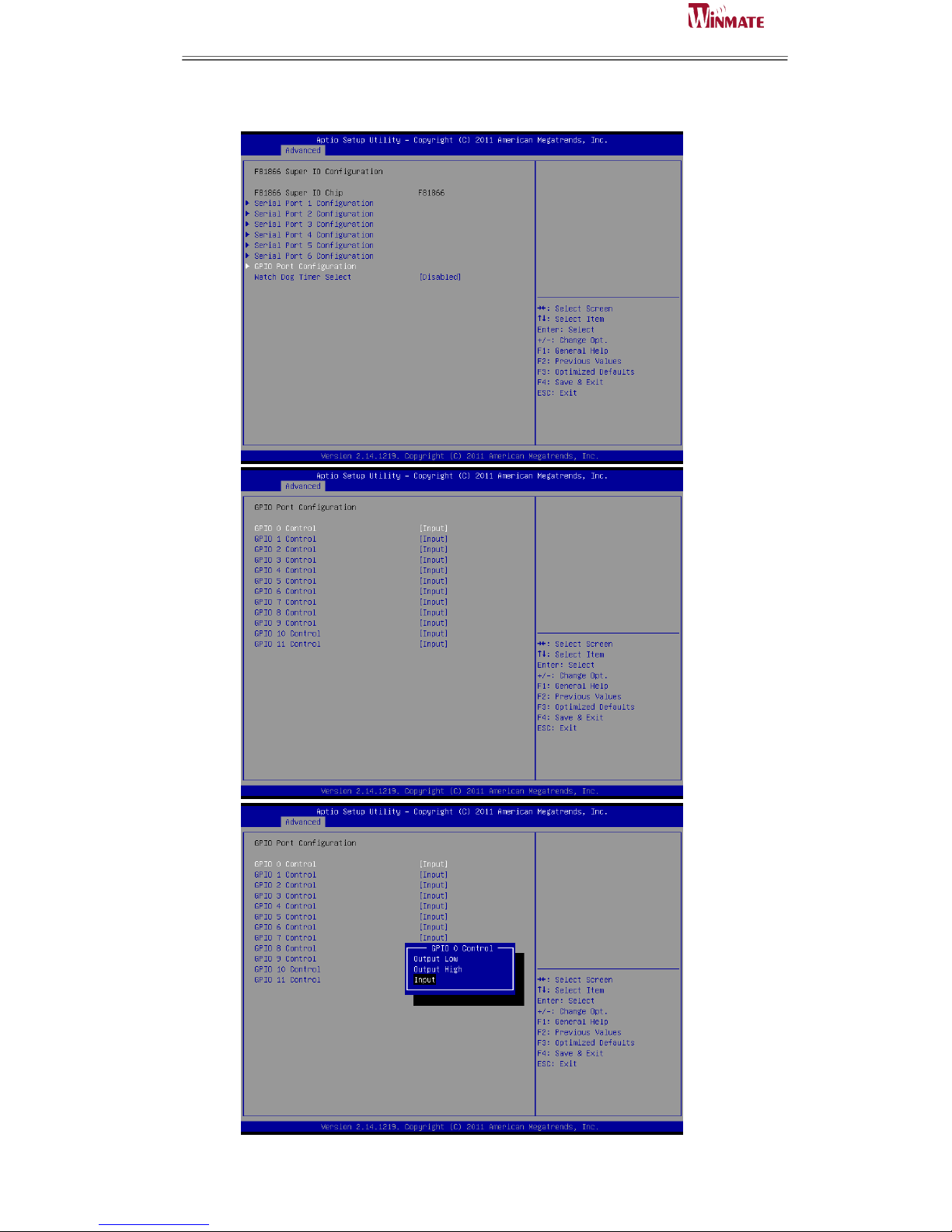
GPIO
Page 69
ID31 Motherboard User Manual
61
ID31 Motherboard User Manual /
Engineering Spec.
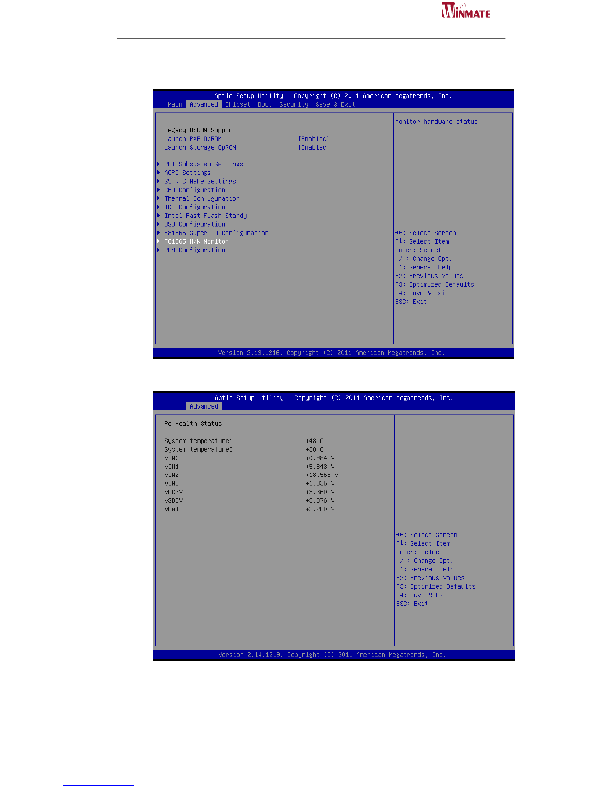
F81865 H/W Monitor
Page 70
ID31 Motherboard User Manual
62
ID31 Motherboard User Manual /
Engineering Spec.
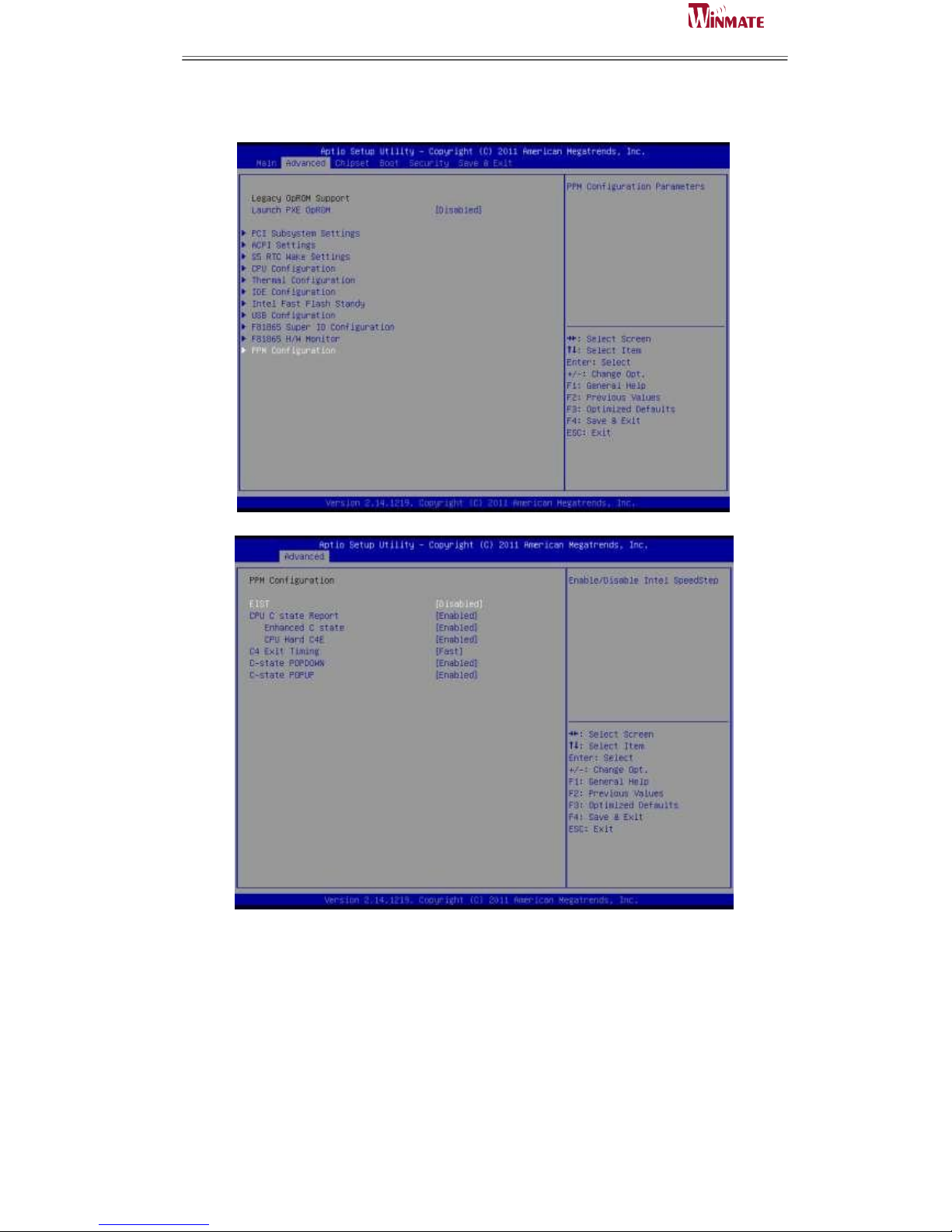
PPM Configuration
EIST
Enable/Disable Intel SpeedStep.
CPU C state Report
Enable/Disable CPU C state report to OS.
C4 Exit Timing
This option controls a programmable time for the CPU voltage to stabilize when exiting from a C4
state.
Page 71
ID31 Motherboard User Manual
63
ID31 Motherboard User Manual /
Engineering Spec.
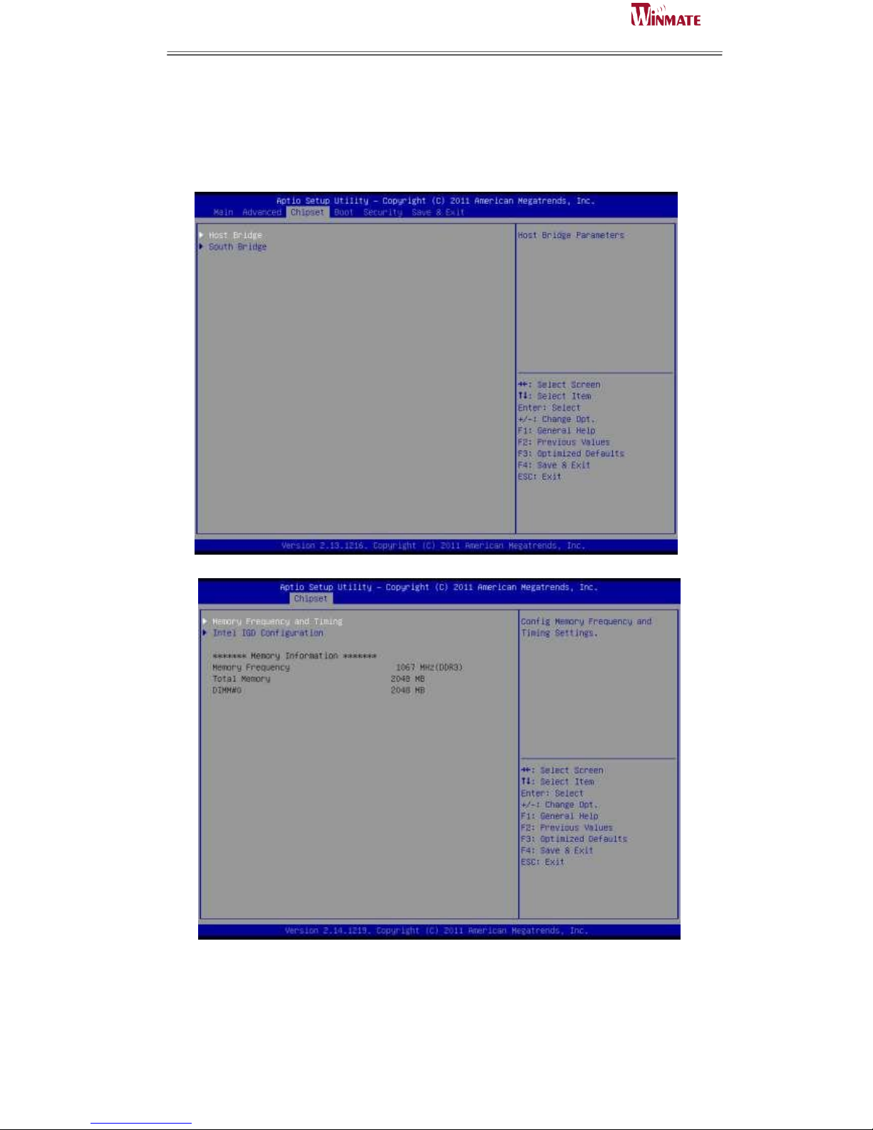
Chipset
This section allows you to configure and improve your system and allows you to set up some system
features according to your preference.
Memory Frequency and Timing
Page 72
ID31 Motherboard User Manual
64
ID31 Motherboard User Manual /
Engineering Spec.
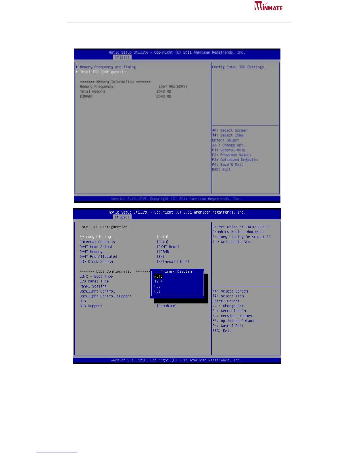
Intel IGD Configuration
Primary Display
Select which of IGFX/PEG/PCI Graphics device should be Primary display.
Internal Graphics
Keep IGD enabled based on the setup options.
Page 73
ID31 Motherboard User Manual
65
ID31 Motherboard User Manual /
Engineering Spec.
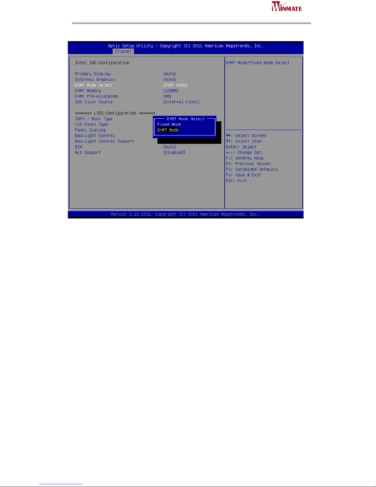
DVMT
Intel's Dynamic Video Memory Technology (DVMT) takes that concept further by allowing the system
to dynamically allocate memory resources according to the demands of the system at any point in time.
The key idea in DVMT is to improve the efficiency of the memory allocated to either system or
graphics processor.
IGD Clock Source
IGD clock selection.
LCD Panel Type
Select LCD panel used by Internal Graphics Device by selecting the appropriate setup item.
Panel Scaling
Select the LCD panel scaling option used by the Internal Graphics Device.
Backlight Control
IGD clock selection.
Backlight Control Support
Back Light Control Setting.
BIA
Auto:GMCH Use VBT Default; Level n: Enabled with Selected Aggressiveness Level, .
ALS Support
Valid only for ACPI.
Page 74
ID31 Motherboard User Manual
66
ID31 Motherboard User Manual /
Engineering Spec.
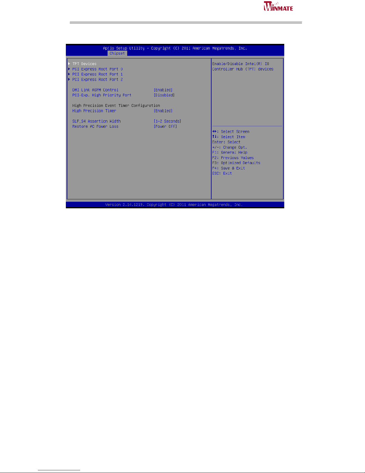
TPT Devices
Enable/Disable Intel IO controller hub device
PCI Express Root Port 0/1/2/
PCI Express root port settings
DMI Link ASPM Control
The Desktop Management Interface (DMI) generates a standard framework for
managing and tracking components in a desktop, notebook or server computer, by
abstracting these components from the software that manages them.
PCI-Exp. High Priority Port
Select a PCI Express High Priority Port.
Page 75
ID31 Motherboard User Manual
67
ID31 Motherboard User Manual /
Engineering Spec.
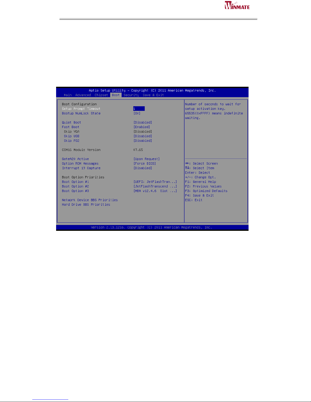
5.3 Boot
Setup Prompt Timeout
Number of seconds to wait for setup activation key. 65535 (0xFFFF) means indefinite
waiting.
Default: 1
Bootup NumLock State
Select the keyboard NumLock State
Default: On
Quiet Boot
Enable or Disable Quiet Boot Option.
Default: Disable
GateA20 Active
UPON REQUEST – GA20 can be disabled using BIOS services. Always – do not
allow disabling GA20; this option is useful when any RT code is executed above
1MB.
Option ROM Messages
Set display mode for Option ROM. Options are Force BIOS and Keep Current.
Interrupt 19 Canture
Enable: Allows Option ROMs to trap Int 19.
Page 76
ID31 Motherboard User Manual
68
ID31 Motherboard User Manual /
Engineering Spec.
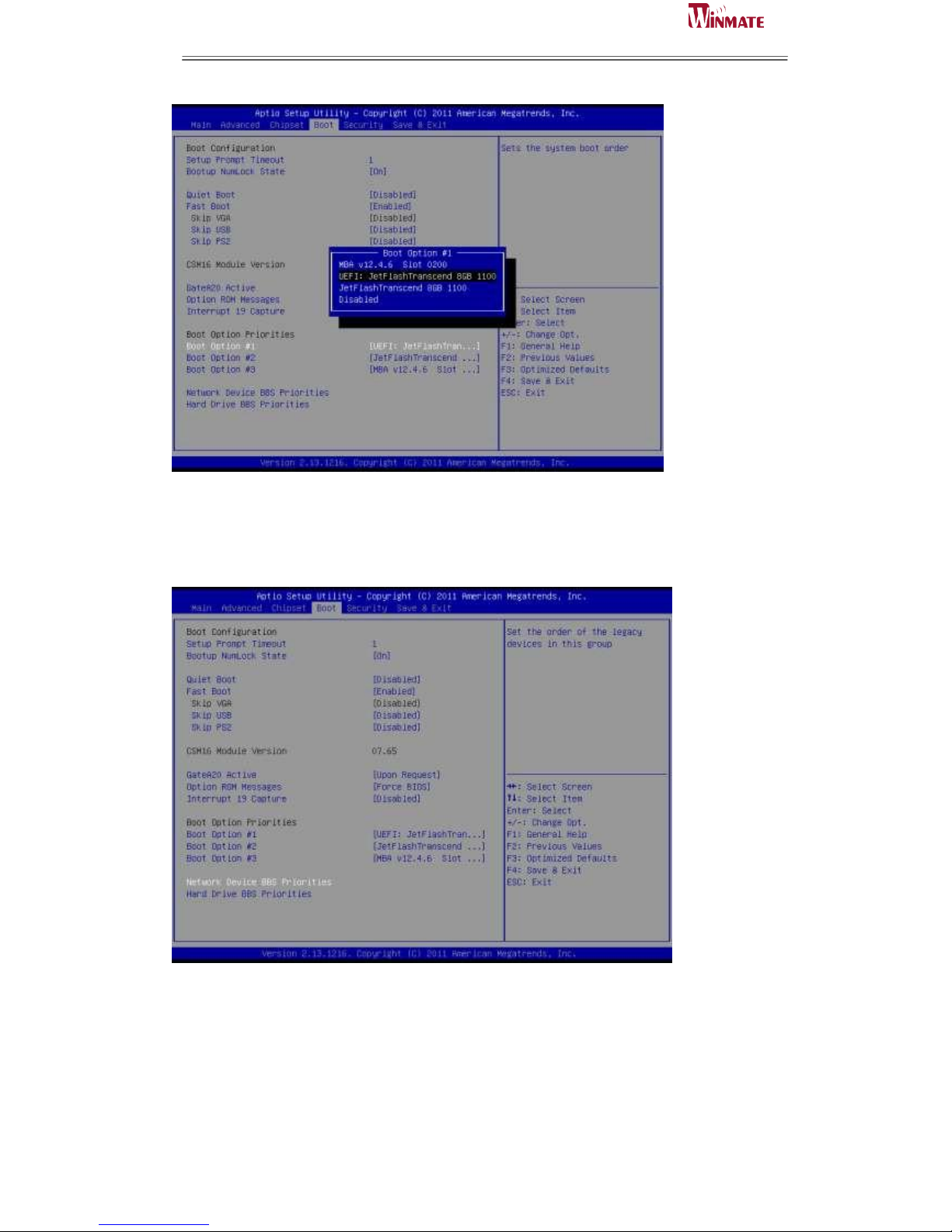
Boot Option
This option shows the priorities of the boot options. User can change the priorities by
selecting the particular boot option. The boot option selected in Boot option #1 will be
the first priority, followed by second, third and so on.
Network/Hard Device BBS Priorities
It will list all the Boot options that are configured as Network/Hard Drive. User can
change the priority as similar to the main boot option priorities. The first boot option
will be having top boot priority and will appear at the boot option priorities and boot
order.
Page 77
ID31 Motherboard User Manual
69
ID31 Motherboard User Manual /
Engineering Spec.
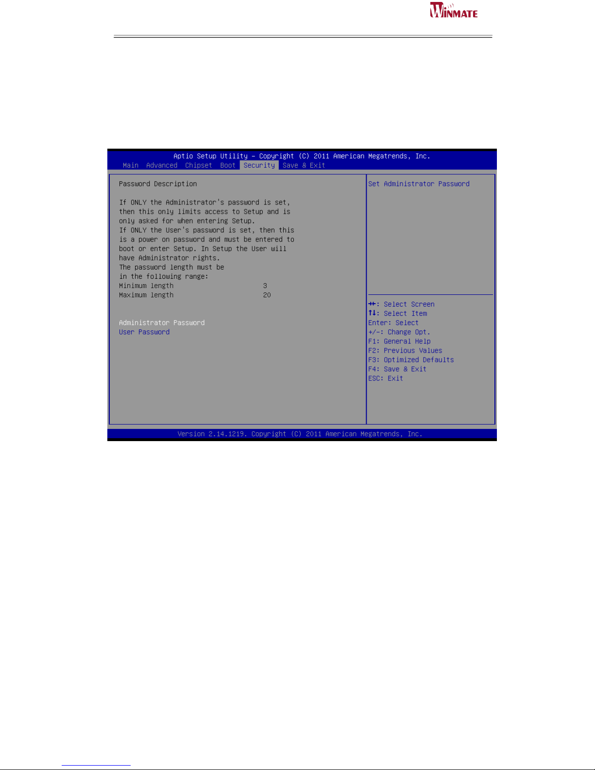
5.4 Security
Administrator Password
This section allows you to configure and improve your system and allows you to set
up some system features according to your preference.
Administrator Password
Set Setup Administrator Password.
User Password
Set User Password.
Page 78
ID31 Motherboard User Manual
70
ID31 Motherboard User Manual /
Engineering Spec.
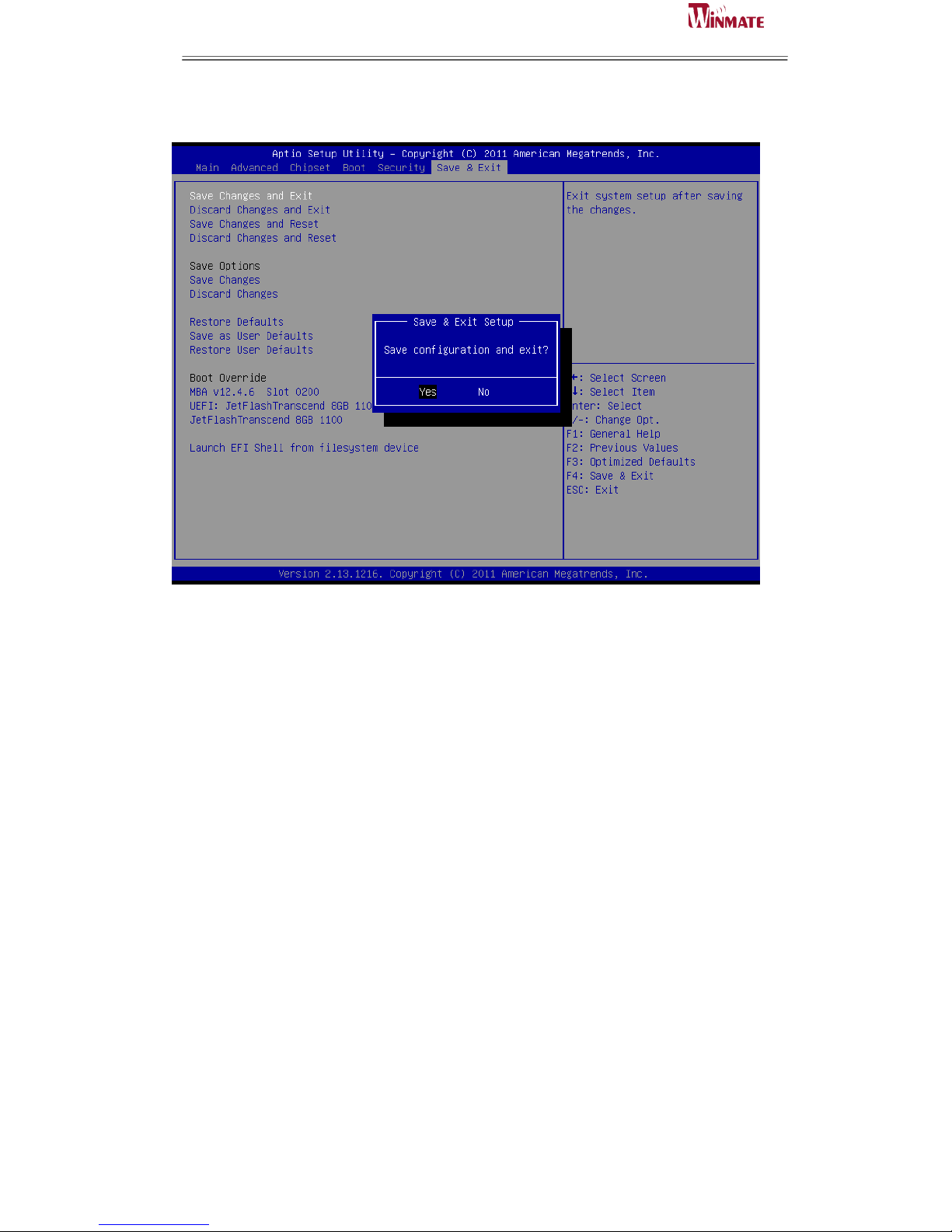
5.5 Save & Exit
Save Changes and Exit
Exit system setup after saving the changes.
Disacard Changes and Exit
Exit system setup without saving any changes.
Save Changes and Reset
Reset the system after saving the changes.
Discard Changes and Reset
Reset system setup without saving any changes.
Save Changes
Save Changes done so far to any of the setup options.
Discard Changes
Discard Changes done so far to any of the setup options.
Restore Defaults
Restore/Load Defaults values for all the setup options.
Save as User Defaults
Save the changes done so far as User Defaults.
Restore User Defaults
Restore the User Defaults to all the setup options.
Launch EFI Shell from filesystem devices
Attempts to launch EFI shell application from one of the available filesystem devices.
Page 79

ID31 Motherboard User Manual
71
ID31 Motherboard User Manual /
Engineering Spec.
Note1: Digital I/O Sample Code
//File of the Main.cpp
//===========================================================
//This code is for test IA30 Super I/O.
//===========================================================
#include <dos.h>
#include <conio.h>
#include <stdio.h>
#include <stdlib.h>
//============================================================
#define W83627EHG_INDEX_PORT 0x2E
#define W83627EHG_DATA_PORT 0x2F
//============================================================
#define W83627EHG_REG_LD 0x07
//============================================================
#define W83627EHG_UNLOCK 0x87
#define W83627EHG_LOCK 0xAA
//============================================================
void ClrKbBuf(void);
void Unlock_W83627EHG(void);
void Lock_W83627EHG(void);
void Set_W83627EHG_Reg(unsigned char,unsigned char);
unsigned char Get_W83627EHG_Reg(unsigned char);
int main ();
//============================================================
int main ()
{
unsigned char ucDO = 0; //data for digital output
unsigned char ucDI; //data for digital input
unsigned char ucBuf;
Set_W83627EHG_Reg(0x07,0x07);//switch to logic device 7
// PIN 121~128 function select
// Bit0 = 0 -> Game Port.
// = 1 -> GPIO1.
Page 80

ID31 Motherboard User Manual
72
ID31 Motherboard User Manual /
Engineering Spec.
ucBuf = Get_W83627EHG_Reg(0x29);
Set_W83627EHG_Reg(0x29,ucBuf|0x01);
// Bit0 = 0 -> GPIO1 is inactive.
// Bit1 = 1 -> Activate GPIO1.
ucBuf = Get_W83627EHG_Reg(0x30);
Set_W83627EHG_Reg(0x30,ucBuf|0x01);//Activate GPIO1
Set_W83627EHG_Reg(0xF0,0x0F);//switch GPIO Input(1)/Output(0) port
Set_W83627EHG_Reg(0xF1, 0x00); //clear
ucDI = Get_W83627EHG_Reg(0xF1) & 0x0F;
ClrKbBuf();
while(1)
{
ucDO++;
Set_W83627EHG_Reg(0xF1, ((ucDO & 0x0F) << 4));
ucBuf = Get_W83627EHG_Reg(0xF1) & 0x0F;
if (ucBuf != ucDI)
{
ucDI = ucBuf;
printf("Digital I/O Input Changed. Current Data is 0x%X\n",ucDI);
}
if (kbhit())
{
getch();
break;
}
delay(500);
}
return 0;
}
//============================================================
void ClrKbBuf(void)
{
while(kbhit())
{ getch(); }
}
Page 81

ID31 Motherboard User Manual
73
ID31 Motherboard User Manual /
Engineering Spec.
//---------------------------------------------------------------------------
void Unlock_W83627EHG (void)
{
outportb(W83627EHG_INDEX_PORT, W83627EHG_UNLOCK);
outportb(W83627EHG_INDEX_PORT, W83627EHG_UNLOCK);
}
//============================================================
void Lock_W83627EHG (void)
{
outportb(W83627EHG_INDEX_PORT, W83627EHG_LOCK);
}
//============================================================
void Set_W83627EHG_Reg( unsigned char REG, unsigned char DATA)
{
Unlock_W83627EHG();
outportb(W83627EHG_INDEX_PORT, REG);
outportb(W83627EHG_DATA_PORT, DATA);
Lock_W83627EHG();
}
//============================================================
unsigned char Get_W83627EHG_Reg( unsigned char REG)
{
unsigned char Result;
Unlock_W83627EHG();
outportb(W83627EHG_INDEX_PORT, REG);
Result = inportb(W83627EHG_DATA_PORT);
Lock_W83627EHG();
return Result;
}
//============================================================
Page 82

ID31 Motherboard User Manual
74
ID31 Motherboard User Manual /
Engineering Spec.
Note2: Watchdog Sample Code
//File of the Watchdog.cpp
//============================================================
//This Sample code is for Watchdog timer configuration
//============================================================
//============================================================
#include <dos.h>
#include <conio.h>
#include <stdio.h>
#include <stdlib.h>
//============================================================
#define W83627_INDEX_PORT 0x2E
#define W83627_DATA_PORT 0x2F
#define W83627_UNLOCK 0x87
#define W83627_LOCK 0xAA
//#define Watchdog_timeout 10
//============================================================
void Unlock_W83627(void);
void Lock_W83627(void);
void Set_W83627_Reg(unsigned char,unsigned char);
unsigned char Get_W83627_Reg(unsigned char);
//============================================================
int main ()
{
int Watchdog_timeout = 10;
printf("Input Watchdog Timer time-out value [0-255] : ");
scanf("%d",&Watchdog_timeout);
if(Watchdog_timeout <= 0 || Watchdog_timeout > 255)
{
printf("Time-out value out of range!!\n\n");
printf("Input Watchdog Timer time-out value [0-255] : ");
scanf("%d",&Watchdog_timeout);
Page 83

ID31 Motherboard User Manual
75
ID31 Motherboard User Manual /
Engineering Spec.
}
Set_W83627_Reg(0x07,0x08);//switch to logic device 8
Set_W83627_Reg(0x30,0x01);//Activate watchdog
Set_W83627_Reg(0xF5,0x06);//Select WDTO# count mode.Second Mode.
Set_W83627_Reg(0xF6,Watchdog_timeout); //Set Watch Dog Timer Time-out
value
//Set_W83627_Reg(0xF7,0xC0); //Clear Watchdog timer event
int i = Watchdog_timeout;
while(1)
{
if (kbhit())
{
if(getch()==0x1B) //Esc
break;
else{
i=Watchdog_timeout; //Reset Watchdog timer
Set_W83627_Reg(0xF6,Watchdog_timeout); //Set Watch Dog
Timer Time-out value
}
}
clrscr();
if(i>0){
i--;
printf("After %2d sec reset computer!\n",i);
printf("Press any key to reset watchdog timer!\n");
printf("Press [Esc] to exit!\n");
}
else
printf("Watchdog timer fail!");
delay(1000);
}
Page 84

ID31 Motherboard User Manual
76
ID31 Motherboard User Manual /
Engineering Spec.
Set_W83627_Reg(0xF6,0); //Disable Watchdog timer
return 0;
}
//---------------------------------------------------------------------------
void Unlock_W83627 (void)
{
outportb(W83627_INDEX_PORT, W83627_UNLOCK);
outportb(W83627_INDEX_PORT, W83627_UNLOCK);
}
//============================================================
void Lock_W83627 (void)
{
outportb(W83627_INDEX_PORT, W83627_LOCK);
}
//============================================================
void Set_W83627_Reg( unsigned char REG, unsigned char DATA)
{
Unlock_W83627();
outportb(W83627_INDEX_PORT, REG);
outportb(W83627_DATA_PORT, DATA);
Lock_W83627();
}
//============================================================
unsigned char Get_W83627_Reg( unsigned char REG)
{
unsigned char Result;
Unlock_W83627();
outportb(W83627_INDEX_PORT, REG);
Result = inportb(W83627_DATA_PORT);
Lock_W83627();
return Result;
}
//============================================================
 Loading...