

Page 1

Embedded Computer
Intel® Core i5-7200U, 2.5 GHz (Turbo to 3.1 GHz)
Intel® Core i5-6200U, 2.3 GHz (Turbo to 2.8 GHz)
I330EAC-IKW
User Manual
Document Version 1.0
Document Part No. 91521110105L
Please read these instructions carefully before using this product, and save this manual for future use.
Page 2

2
I330EAC-IKW Embedded Computer User Manual
Contents
Preface 4
Chapter 1: Introduction 7
1.1 Features 7
1.2 Package Contents 7
1.3 Product Overview 8
Chapter 2: Hardware Installation 9
2.1 Mounting 9
2.2 Connecting the Power 9
Chapter 3: Operating the Device 10
3.1 How to Enable Watchdog 10
3.2 S4 Wake on LAN 11
3.3 Changing Serial Port Settings 12
3.4 Changing DIDO Settings 15
3.5 Changing NMEA Port Settings 16
3.6 Using Recovery Wizard to Restore Computer 17
Chapter 4: INSYDE H20 BIOS Setup 18
4.1 How and When to Use BIOS Setup 18
4.2 BIOS Functions 19
4.2.1 Main Menu 19
4.2.2 Advanced 20
4.2.3 Boot 34
4.2.4 Security 37
4.2.5 Power 38
4.2.5 Exit 39
Chapter 5: Driver Installation 40
5.1 Chipset Driver 40
5.2 Graphic Driver 42
5.3 Management Engine (ME) 46
5.4 Audio Driver 49
5.5 Ethernet Driver 50
5.6 Watchdog Driver 53
5.9 Option Devices Driver Installation 56
5.9.1 WIDOM Driver 56
5.9.2 U2RS4 Driver 68
5.9.3 DIDO Driver 70
5.10 Option Device Configuration Tool Installation 71
Appendix 74
Appendix A: Hardware Specifications 74
Page 3

3
Preface
Appendix B: System Dimensions 75
Appendix C: Software Developer Support 75
Page 4

4
I330EAC-IKW Embedded Computer User Manual
Preface
Copyright Notice
No part of this document may be reproduced, copied, translated, or transmitted in any form or
by any means, electronic or mechanical, for any purpose, without the prior written permission
of the original manufacturer.
Trademark Acknowledgement
Brand and product names are trademarks or registered trademarks of their respective owners.
Disclaimer
We reserve the right to make changes, without notice, to any product, including circuits and/or
software described or contained in this manual in order to improve design and/or performance.
We assume no responsibility or liability for the use of the described product(s) conveys no
license or title under any patent, copyright, or masks work rights to these products, and make
no representations or warranties that these products are free from patent, copyright, or mask
work right infringement, unless otherwise specified. Applications that are described in this
manual are for illustration purposes only. We make no representation or guarantee that such
application will be suitable for the specified use without further testing or modification.
Warranty
Our warranty guarantees that each of its products will be free from material and workmanship
defects for a period of one year from the invoice date. If the customer discovers a defect, we
will, at his/her option, repair or replace the defective product at no charge to the customer,
provide it is returned during the warranty period of one year, with transportation charges
prepaid. The returned product must be properly packaged in its original packaging to obtain
warranty service. If the serial number and the product shipping data differ by over 30 days, the
in-warranty service will be made according to the shipping date. In the serial numbers the third
and fourth two digits give the year of manufacture, and the fifth digit means the month (e. g.,
with A for October, B for November and C for December).
For example, the serial number 1W18Axxxxxxxx means October of year 2018.
Customer Service
We provide a service guide for any problem by the following steps: First, visit the website of
our distributor to find the update information about the product. Second, contact with your
distributor, sales representative, or our customer service center for technical support if you
need additional assistance.
You may need the following information ready before you call:
Product serial number
Software (OS, version, application software, etc.)
Description of complete problem
The exact wording of any error messages
In addition, free technical support is available from our engineers every business day. We are
always ready to give advice on application requirements or specific information on the installation
and operation of any of our products.
Page 5

5
Preface
Note:
A note is used to emphasize helpful information
Important:
An important note indicates information that is important for you to know.
Caution A Caution alert indicates potential damage to hardware and explains how
to avoid the potential problem.
Attention Une alerte d’attention indique un dommage possible à l’équipement et
explique comment éviter le problème potentiel.
Warning! An Electrical Shock Warning indicates the potential harm from electrical
hazards and how to avoid the potential problem.
Avertissement! Un Avertissement de Choc Électrique indique le potentiel de
chocs sur des emplacements électriques et comment éviter ces problèmes.
Warning! Always completely disconnect the power cord from your chassis
whenever you work with the hardware. Do not make connections while the power
is on. Sensitive electronic components can be damaged by sudden power
surges. Only experienced electronics personnel should open the PC chassis.
Avertissement! Toujours débrancher le cordon d’alimentation du chassis
lorsque vous travaillez sur celui-ci. Ne pas brancher de connections lorsque
l’alimentation est présente. Des composantes électroniques sensibles peuvent
être endommagées par des sauts d’alimentation. Seulement du personnel
expérimenté devrait ouvrir ces chassis.
Caution Always ground yourself to remove any static charge before touching
the CPU card. Modern electronic devices are very sensitive to static electric
charges. As a safety precaution, use a grounding wrist strap at all times. Place
all electronic components in a static-dissipative surface or static-shielded bag
when they are not in the chassis.
Attention Toujours verifier votre mise à la terre afin d’éliminer toute charge
statique avant de toucher la carte CPU. Les équipements électroniques
moderns sont très sensibles aux décharges d’électricité statique. Toujours
utiliser un bracelet de mise à la terre comme précaution. Placer toutes les
composantes électroniques sur une surface conçue pour dissiper les charge,
ou dans un sac anti-statique lorsqu’elles ne sont pas dans le chassis.
Alternating Current The Protective Conductor Terminal (Earth Ground)
symbol indicates the potential risk of serious electrical shock due to improper
grounding.
Mise à le terre ! Le symbole de Mise à Terre indique le risqué potential de
choc électrique grave à la terre incorrecte.
Advisory Conventions
Four types of advisories are used throughout the user manual to provide helpful information or to
alert you to the potential for hardware damage or personal injury. These are Notes, Important,
Cautions, and Warnings. The following is an example of each type of advisory.
Safety Information
Page 6

6
I330EAC-IKW Embedded Computer User Manual
This device complies with part 15 FCC rules.
Operation is subject to the following two conditions:
This device may not cause harmful interference.
This device must accept any interference received including
interference that may cause undesired operation.
This equipment is in conformity with the requirement of the
following EU legislations and harmonized standards. Product also
complies with the Council directions.
Important Information
Federal Communications Commission Radio Frequency Interface Statement
This equipment has been tested and found to comply with the limits for a class "B" digital
device, pursuant to part 15 of the FCC rules. These limits are designed to provide reasonable
protection against harmful interference when the equipment is operated in a commercial
environment. This equipment generates, uses, and can radiate radio frequency energy and, if
not installed and used in accordance with the instruction manual, may cause harmful
interference to radio communications. Operation of this equipment in a residential area is likely
to cause harmful interference in which case the user will be required to correct the interference
at him own expense.
EC Declaration of Conformity
Electromagnetic Compatibility Directive (2014/30/EU)
EN55024: 2010 EN 55022: 2010 Class B
o IEC61000-4-2: 2009
o IEC61000-4-3: 2006+A1: 2007+A2: 2010
o IEC61000-4-4: 2012
o IEC61000-4-5: 2014
o IEC61000-4-6: 2013
o IEC61000-4-8: 2010
o IEC61000-4-11: 2004
EN55022: 2010/AC:2011
EN61000-3-2:2014
EN61000-3-3:2013
Low Voltage Directive (2014/35/EU)
EN 60950-1:2006/A11:2009/A1:2010/A12:2011/ A2:2013
Page 7

7
Chapter 1: Introduction
I330EAC-IKW Embedded
Computer
Quick Start Guide
(Hardcopy)
Driver CD & User Manual
Power Cord
AC Adapter
12V/ 84W
Chapter 1: Introduction
Congratulations on purchasing Winmate® EAC IKW Embedded Computer. EAC IKW with 7th
Generation Intel® i5-7200U offers high performance computing power and outstanding video
processing. EAC IKW suitable for Factory Automation, Machine Vision, Surveillance, Machine
Automation and other high-performance applications.
1.1 Features
Winmate® I330EAC-IKW Embedded Computer offers the following features:
Design for Industrial Automation, M2M application
Intel® Core i5-7200U, 2.5 GHz (turbo to 3.1 GHz)
Intel® Core i5-6200U, 2.3 GHz (turbo to 2.8 GHz) (Optional)
1 x DDR4L-2133 SODIMM, max.16 GB
8 x Isolated DIDO, 4 In/4 Out (Optional)
4 x Isolated RS-422/485, programmable by software (Optional)
2.5" Removable SSD/HDD
Fanless, high efficiency thermal design with sealed construction
1.2 Package Contents
Carefully remove the box and unpack your device. Please check if all the items listed below are
inside your package. If any of these items are missing or damaged contact us immediately.
Standard factory shipment list:
Page 8
8
I330EAC-IKW Embedded Computer User Manual
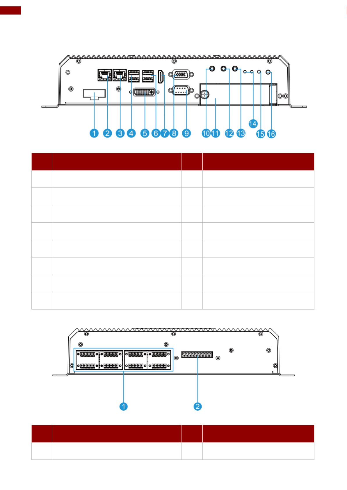
№
Description
№
Description
❶
DC Input
❾
RS232/422/485
❷
Giga LAN
❿
Mic in
❸
Giga LAN
⓫
2.5” SSD Slot x 2
❹
USB 3.0 x 2
⓬
Line in
❺
DVI
⓭
Line out
❻
USB 3.0 x 2
⓮
LED indicator
❼
HDMI
⓯
Reset
❽
VGA
⓰
Power Vutton
№
Description
№
Description
❶
8 x NMEA 0183 (Optional)
❷
8 x Isolated DIDO (Optional)
1.3 Product Overview
Front Side I/O Connectors
Rear Side I/O Connectors
Page 9
9
Chapter 2: Hardware Installation
Warning!
Ensure voltage and polarity is compliant with the DC input. Improper input voltage or
polarity can cause system damage.
Avertissement! Assurez-vous que la tension et la polarité sont conformes à
l'entrée CC. Une tension d'entrée ou une polarité incorrecte peut endommager le
système.
Warning!
Connect the I330EAC-IKW either to AC power or DC power. Do not perform both
connections at the same time.
Avertissement! Connectez l'I330EAC-IKW à une alimentation CA ou CC.
N'effectuez pas les deux connexions en même temps.
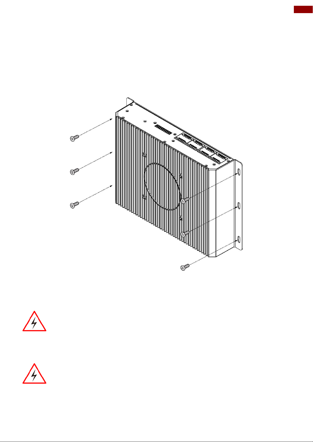
Chapter 2: Hardware Installation
2.1 Mounting
I330EAC-IKW Embedded Computer supports table mounting.
Mounting Instruction:
1. Fasten screws to secure L-shape mounting brackets to the I330EAC-IKW.
2. Insert the I330EAC-IKW into the fixture (ex. rack) and fasten screws to secure the unit.
2.2 Connecting the Power
The DC power supply connector of the I330EAC-IKW Embedded Computer is on the front panel.
Connecting to DC Power
Connect open wire cable (not supplied by Winmate) to 9-36V DC, maximum power source 220W.
Page 10

10
I330EAC-IKW Embedded Computer User Manual
Example:
Every 10 min watchdog will monitor the system, in
case any error occurs the system will restart
automatically when the countdown time reaches 0.
Every 9 min watchdog timer will be reset to 10 min.
Setting
Description
Watchdog Countdown Time
The system automaticity restarts when this countdown
time reaches zero. Default: 10 min
Periodically Feed Time
To set a cycle time to automatically reset watchdog timer.
Default: 9 min
Enable / Disable
Enable or disable watchdog. Default: Enable
Chapter 3: Operating the Device
3.1 How to Enable Watchdog
Download Winmate Watchdog utility to enable Watchdog. Find more information in “Watchdog
Guide” that you can download from Download Center.
To enable watchdog in Watchdog AP follow the instructions below:
1. On the right bottom side of the desktop screen, click triangle button to show hidden
icons.
2. Click icon to open Watchdog utility.
3. Set countdown time and periodically feed time, or disable watchdog.
Page 11
11
Chapter 3: Operating the Device
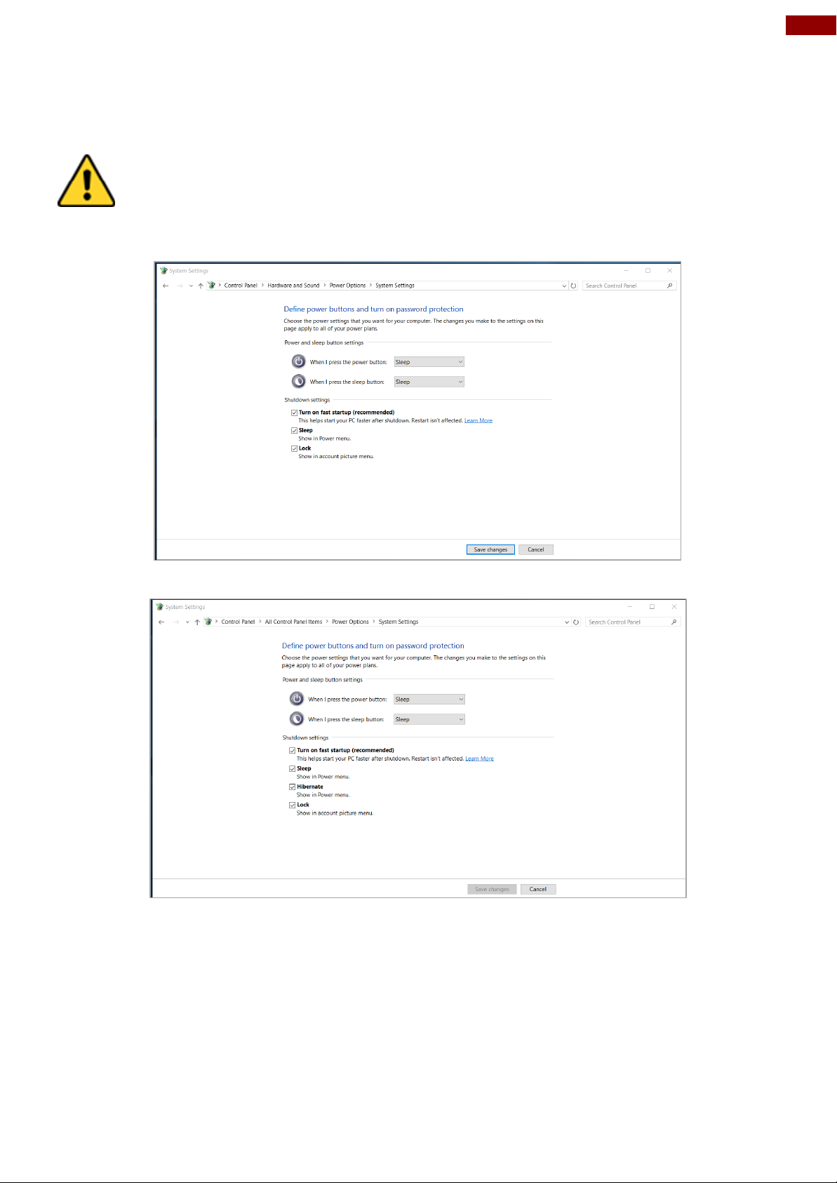
Caution Check if your system storage capacity is 32 GB before entering
Hibernation mode.
Attention Vérifiez si la capacité de stockage de votre système est de 32 Go avant
de passer en mode Veille prolongée.
3.2 S4 Wake on LAN
In Windows 10 OS shutdown settings will not have Hibernate mode if your storage capacity is
below 32 GB.
Storage capacity below 32 GB:
Storage capacity above 32 GB
Page 12

12
I330EAC-IKW Embedded Computer User Manual
3.3 Changing Serial Port Settings
You can change serial port settings in BIOS.
To change serial port settings (Kaby Lake Core i5-7200U):
1. To enter the BIOS setup connect an external USB keyboard, external monitor and
quickly press Del key when the prompt appears on the screen during start up.
2. In BIOS go to Advanced > F81866 Super IO Configuration > Serial Port
Configuration.
3. Change Settings from UART mode to RS232/422/485.
Page 13

13
Chapter 3: Operating the Device
4. Exit BIOS utility.
To change serial port settings (Skylake Core i5-6200U):
5. To enter the BIOS setup connect an external USB keyboard, external monitor and quickly
press Del key when the prompt appears on the screen during start up.
6. In BIOS go to Advanced > F81866 Super IO Configuration.
7. Serial Port Configuration.
Page 14

14
I330EAC-IKW Embedded Computer User Manual
8. Change Settings from UART mode to RS232/422/485.
9. Exit BIOS utility.
Page 15

15
Chapter 3: Operating the Device
3.4 Changing DIDO Settings
Download Option Device Config Tool from Winmate Download Center or driver CD that comes
in a package with Box PC.
To change DIDO Settings:
1. Click the Option Device Config Tool icon on the desktop.
2. Click DI4DO4.
3. Adjust DI4DO4 settings and press Start.
Page 16

16
I330EAC-IKW Embedded Computer User Manual
3.5 Changing NMEA Port Settings
Download Option Device Config Tool from Winmate Download Center or driver CD that comes
in a package with Box PC.
To change DIDO Settings:
4. Click the Option Device Config Tool icon on the desktop.
5. Click U2RS4.
6. Adjust U2RS4 settings and press Start.
Page 17

17
Chapter 3: Operating the Device
Note: Before starting the recovery process, make sure to backup all user data.
The data will be lost after the recovery process.
Important: Before starting the recovery process, remove the PCI/ PCIe card
and CFast card.
3.6 Using Recovery Wizard to Restore Computer
To enable quick one-key recovery procedure:
1. Connect the computer to the power source. Make sure the computer stays plugged in to
power source during the recovery process.
2. Turn on the computer, and when the boot screen shows up, press Tab+ F6 to initiate the
Recovery Wizard.
3. The following screen shows the Recovery Wizard. Click Recovery button to continue.
4. A warning message about data loss will show up. Make sure the data is backed up before
recovery, and click Yes to continue.
Wait the recovery process to complete. During the recovery process, a command prompt will show
up to indicate the percent of recovery process complete. The system will restart automatically after
recovery completed.
Page 18

18
I330EAC-IKW Embedded Computer User Manual
Important: Updated BIOS version may be published after the manual
released. Check the latest version of BIOS on the website.
Key
Function
Del
Enters the BIOS setup menu.
F7
Display the boot menu. Lists all bootable devices that are
connected to the system. With cursor ↑and cursor ↓and by
pressing <ENTER>, select the device used for the boot.
Pause
Pressing the [Pause] key stops the POST. Press any other key to
resume the POST.
Key
Function
F1
Help
F5/ F6
Change Values
F9
Setup Defaults
F10
Save & Exit
Esc
Exit
Enter
Select SubMenu
↑/ ↓
Select Item
← / →
Select Item
Note: You can press the F1, F2, F3, F4, –/+, and Esc keys by connecting
a USB keyboard to your computer.
Chapter 4: INSYDE H20 BIOS Setup
This chapter describes the different settings available in the INSYDE BIOS that comes with the
board. This chapter offers information on the BIOS installation utility.
4.1 How and When to Use BIOS Setup
To enter the BIOS setup, you need to connect an external USB keyboard, external monitor and
press Del key when the prompt appears on the screen during start up. The prompt screen shows
only few seconds so need press Del key quickly.
You may need to run BIOS setup utility for reasons listed below:
1. Error message on screen indicates to check BIOS setup
2. Restoring the factory default settings.
3. Modifying the specific hardware specifications
4. Necessity to optimize specifications
BIOS Navigation Keys
The following keys are enabled during POST:
The following Keys can be used after entering the BIOS Setup.
For items marked ► press <Enter> for more options.
Page 19

19
Chapter 4: INSYDE H20 BIOS Setup
BIOS
Setting
Description
Setting Option
Effect
Language
Displays the system
language. [English] is
set up by default.
Adjustment of
the
language
Set the language in
other language. The
language in this
device is English.
System
Time
This is current time
setting. The time is
maintained by the
battery when the
device is turned off.
Date and time
changes.
Set the time in the
format:
[hh/mm/ss]
System Date
This is current date
setting.
Date and time
changes.
Set the date in the
format [mm/dd/yyyy];
4.2 BIOS Functions
4.2.1 Main Menu
The Main menu displays the basic information about your system including BIOS version,
processor RC version, system language, time, and date. When you enter BIOS setup, the first
menu that appears on the screen is the main menu. It contains the system information including
BIOS version, processor RC version, system language, time, and date.
Page 20
20
I330EAC-IKW Embedded Computer User Manual
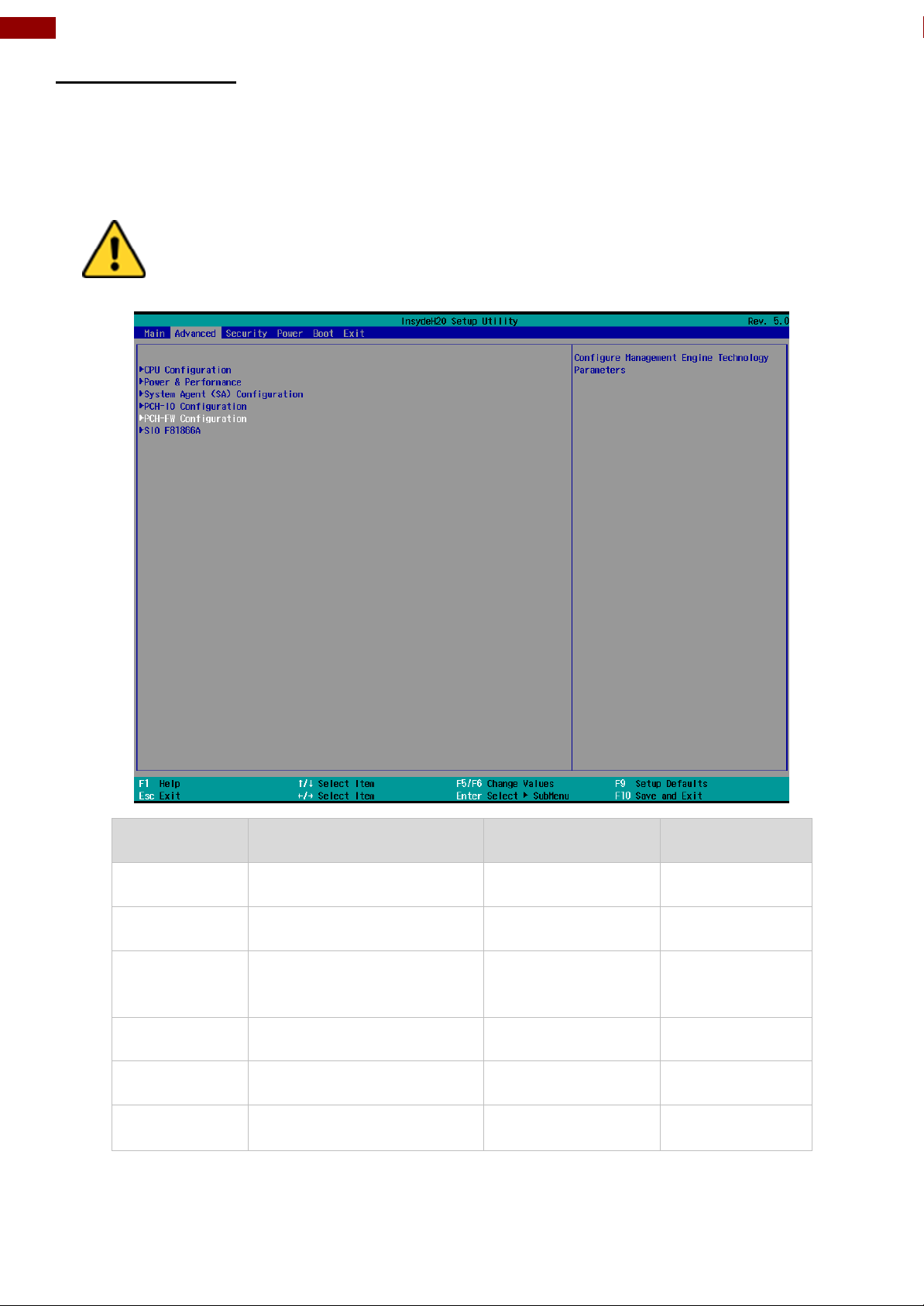
Caution Handle advanced BIOS settings page with caution. Any changes
can affect the operation of your computer.
BIOS Setting
Description
Setting Option
Effect
CPU
Configuration
Configures Trusted
Computing parameters
Enter
Opens
submenu
Power &
Performance
Configures Power &
Performance parameters
Enter
Opens
submenu
System Agent
Configuration
Configures System Agent
Configuration parameters
Enter
Opens
submenu
PCH-OI
Configuration
Configures PCH-OI
parameters
Enter
Opens
submenu
PCH-FM
Configuration
Configures PCH-FM
parameters
Enter
Opens
submenu
SIO F81866A
Configures SIO F81866A
parameters
Enter
Opens
submenu
4.2.2 Advanced
Select the Advanced Tab from the setup menu to enter the advanced BIOS setup screen. You
can select any of the items on the left frame of the screen to go to the sub menu for the item,
such as CPU Configuration. You can use the <Arrow> keys enter all advanced BIOS setup
options. The advanced BIOS setup menu is shown below. The submenus described on the
following pages.
Page 21

21
Chapter 4: INSYDE H20 BIOS Setup
BIOS Setting
Description
Setting Option
Effect
Intel (VMM)
Virtualization
Technology
Enable or disable
Intel Virtualization
Technology.
Enable/Disable
When enabled, a
VMM can utilize
the additional
hardware
capabilities
provided by
Vanderpool
Technology.
Active Processor
Cores
Number of core to
enable in each
processor
package
AII / 1 / 2/ 3
Select number of
core to enable in
each processor
package
Hyper Threading
Intel HyperThreading
Technology allows
a single processor
to execute two or
more separate
threads
concurrently.
Enable /
Disable
Enable or disable
Hyper Threading
AES
Enable or disable
AES (Advanced
Encyption
Standard)
Enable/Disable
Enable or disable
AES
4.2.2.1 CPU Configuration
Page 22
22
I330EAC-IKW Embedded Computer User Manual
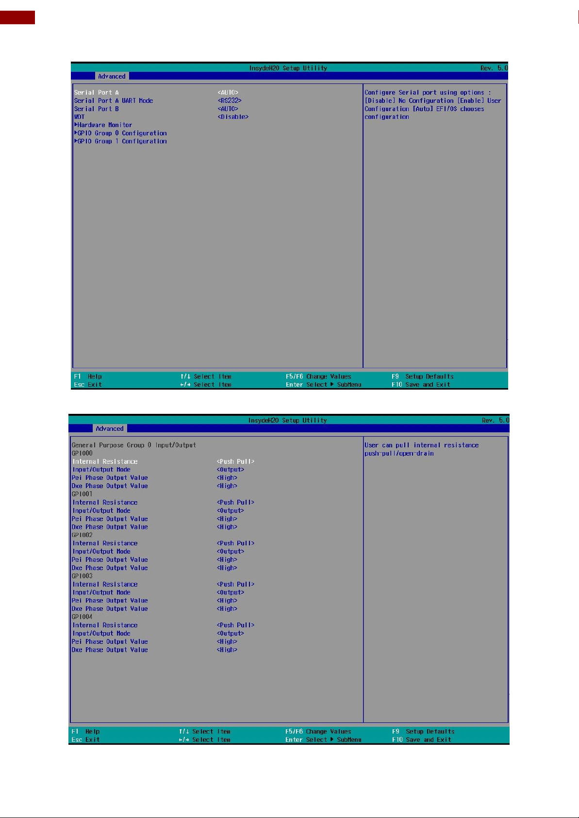
4.2.2.2 F81886A Configuration
BMP
4.2.2.3 GPIO Configuration
Page 23

23
Chapter 4: INSYDE H20 BIOS Setup
4.2.2.4 Hardware Monitor
Page 24

24
I330EAC-IKW Embedded Computer User Manual
BIOS
Setting
Description
Setting Option
Effect
PCI Express
Configuration
PCI Express clock
gating enable/disable for
each root port.
Enter
Opens sub-menu
SATA And
RST
Configuration
Enable/ Disable SATA
device
Enter
Opens sub-menu
USB
Configuration
Selectively enable/
disable the
corresponding USB port
from reporting a Device
Connection to the
controller.
Enter
Opens sub-menu
State After
G3
System power state
setting
S0 State
S5 State
4.2.2.5 PCH-IO Configuration
Page 25

25
Chapter 4: INSYDE H20 BIOS Setup
4.2.2.6 PCI Express Configuration
Page 26

26
I330EAC-IKW Embedded Computer User Manual
4.2.2.7 SATA and RST Configuration
4.2.2.8 USB Configuration
Page 27

27
Chapter 4: INSYDE H20 BIOS Setup
4.2.2.9 ME Firmware Configuration
Page 28

28
I330EAC-IKW Embedded Computer User Manual
Page 29

29
Chapter 4: INSYDE H20 BIOS Setup
BIOS Setting
Description
Setting Option
Effect
CPU – Power
Management
Control
Configure CPU –
Power Management
parameters
Enter
Opens sub-menu
4.2.2.10 Power & Performance
Page 30

30
I330EAC-IKW Embedded Computer User Manual
BIOS Setting
Description
Setting Option
Effect
Boot
Performance
Mode
Configure Boot
Performance Mode
parameters
-Max non-turbo
performance
-Max battery
-Turbo
Performance
Select the performance
state that the BIOS will set
starting from reset vector
Intel
SpeedStep (ta)
Configure Intel
SpeedStep (ta)
parameters
Enabled/
Disabled
Allows more than two
frequency ranges to be
supported
Intel Speed
Shift
Technology
Configure Intel
Speed Shift
Technology
parameters
Enabled/
Disabled
Enable/ Disable Intel Speed
Shift Technology support.
Enabling will expose the
CPP v2 interface to allow
for hardware controlled Pstates
-Turbo Mode
Enable or disable
Turbo Mode
Enabled/
Disabled
Enable/ Disable processor
Turbo Mode (requires
EMTTM enabled too). Auto
means enabled, unless max
turbo ratio is bigger than 16
– SKL AO W/A
C states
Enable or disable
C states
Enabled/
Disabled
Enable/ Disable CPU Power
Management. Allows COU
to go to C states when it is
not 100% utilized
Custom Pstate Table
Configure Custom
P-state Table
parameters
Enter
Enters sub-menu
-Number of Pstates
Select the number
of custom P-states.
[Number]
Set the number of custom
P-states. At least 2 states
must be present
Page 31

31
Chapter 4: INSYDE H20 BIOS Setup
BIOS Setting
Description
Setting Option
Effect
Graphics
Configuration
Configure
Graphics
Configuration
parameters
Enter
Opens sub-menu
Vt-d
Intel®
Virtualization
Technology for
Directed I/O
Enabled
Disabled
Vt-d capability
4.2.2.11 System Agent (SA) Configuration
Page 32

32
I330EAC-IKW Embedded Computer User Manual
BIOS Setting
Description
Setting
Option
Effect
Internal Graphics
Internal
Graphics
settings
Auto
Enabled
Disabled
Keep IGFX enabled based on
the setup options
Aperture Size
Select the
aperture size
128MB
256MB
512MB
1024MB
2048 MB
Select the aperture size
Note: Above 4MB MMIO
BIOS assignment is
automatically enabled when
selecting 2048MB aperture.
To use this feature please
disable CSM port
DVMT PreAllocated
Select DVMT
Pre-Allocated
0M~60M
Select DVMT 5.0 PreAllocated (Fixed) Graphic
Memory size used by Internal
Graphic Device
DVMT Total Gfx
Mem
Select DVMT
Total Gfx Mem
256M
128M
MAX
Select DVMT 5.0 Total
Graphic Memory size used by
the Internal Graphic Device
Gfx Low Power
Mode
Select Gfx Low
Power Mode
Enabled/
Disabled
This option is applicable for
SFF only
4.2.2.11.1 Graphics Configuration
Page 33

33
Chapter 4: INSYDE H20 BIOS Setup
BIOS Setting
Description
Setting Option
Effect
Vt-d
Intel®
Virtualization
Technology for
Directed I/O
Enabled
Disabled
Vt-d capability
4.2.2.11.2 Vt-d
Page 34

34
I330EAC-IKW Embedded Computer User Manual
BIOS Setting
Description
Setting
Option
Effect
Boot Type
Boot Type
configuration
UEFI Boot
Type
Select boot type to Dual type,
Legacy type or UEFI type
Quick Boot
Quick Boot
configuration
Enabled
Disabled
Allows InsydeH20 to skip certain
tests while booting. This will
decrease the time needed to
boot the system
Quiet Boot
Quiet Boot
configuration
Enabled
Disabled
Disable or enable booting in text
Mode.
Timeout
Timeout
[Value]
Timeout settings
Automatic
Failover
Enable
If boot to default device fail, it
will directly try to boot next
device
Disable
If boot to default device fail, it
will pop warning message then
go to firmware UI
Boot Type
Order
Boot Type
Order
Enter
Opens sub-menu
4.2.3 Boot
Page 35

35
Chapter 4: INSYDE H20 BIOS Setup
BIOS Setting
Description
Setting Option
Effect
Hard Disk Type
Hard Disk Type
configuration
Enter
Opens Sub-menu
Others
Other
configuration
Enter
Opens Sub-menu
4.2.3.1 Boot Type Order
Page 36

36
I330EAC-IKW Embedded Computer User Manual
4.2.3.1.1 Hard Disk Type
4.2.3.1.2 Others
Page 37

37
Chapter 4: INSYDE H20 BIOS Setup
BIOS Setting
Description
Setting Option
Effect
TrEE Protocol
Version
Choose TrEE
Protocol Version
1.0
1.1
TrEE Protovol
Version: 1.0 or 1.1
TPM Availability
TPM Availability
configuration
Available
Hidden
When hidden don’t
exposes TPM to 0
TPM Operation
TPM Operation
configuration
[ ]
Select one of the
supported
operation to
change TPM2state
Clear TPM
Clear TPM
configuration
[ ]
Select to Clear
TPM
Set Supervisor
Password
Set Supervisor
Password
Enter New
password
Install or Change
the password and
the length of
password must be
greater than one
character
4.2.4 Security
Page 38

38
I330EAC-IKW Embedded Computer User Manual
BIOS Setting
Description
Setting Option
Effect
ACPI S3
ACPI S3
configuration
Disabled
Enabled
Enable/ Disable ACPI
S1/S3 Sleep state
Auto Wake on S5
Auto Wake on S5
configuration
Disabled
By Every Day
By Every Month
Auto Wake on S5, by
Day or Month or fixed
time of every day
4.2.5 Power
Page 39

39
Chapter 4: INSYDE H20 BIOS Setup
4.2.5 Exit
Page 40

40
I330EAC-IKW Embedded Computer User Manual
Chapter 5: Driver Installation
This chapter contains driver installation guide. Follow the instructions below to complete the
installation. You will quickly complete the installation. This chapter provides instructions on
how to install drivers on the I330EAC-IKW Box PC.
5.1 Chipset Driver
Follow instructions below to install Chipset driver.
1. Open the Driver CD (included in the package) and select Chipset driver.
2. Installation window will pop up, select Next.
Page 41

41
Chapter 5: Driver Installation
3. Select Accept to agree with the terms of license agreement.
4. Check the ReadMe file information, select Install to continue.
Page 42

42
I330EAC-IKW Embedded Computer User Manual
5. Wait for the driver to be installed. When installation completed, select Restart Now to
restart your computer.
5.2 Graphic Driver
Follow instructions below to install Graphic driver.
1. Open the Driver CD (included in the package) and select Graphic driver.
Page 43

43
Chapter 5: Driver Installation
2. Installation window will pop up, select Next.
3. Select Accept to agree with the terms of license agreement.
Page 44

44
I330EAC-IKW Embedded Computer User Manual
4. Check the ReadMe file information, select Next to continue.
Page 45

45
Chapter 5: Driver Installation
5. Wait for the driver to be installed.
6. Select Next to continue.
Page 46

46
I330EAC-IKW Embedded Computer User Manual
7. After installation is completed, select “Yes, I want to restart this computer now”, and
click Finish.
5.3 Management Engine (ME)
Follow instructions below to install Management Engine (ME) .
1. Open the Driver CD (included in the package) and select ME driver.
Page 47

47
Chapter 5: Driver Installation
2. Select Next to start the installation.
3. Select Next to agree with the terms of license agreement.
Page 48

48
I330EAC-IKW Embedded Computer User Manual
4. Wait for the driver to be installed.
5. When installation completed, select inish complete installation.
Page 49

49
Chapter 5: Driver Installation
5.4 Audio Driver
Follow instructions below to install Audio driver.
1. Open the Driver CD (included in the package) and select Audio driver.
2. Select Start to continue.
Page 50

50
I330EAC-IKW Embedded Computer User Manual
3. When installation completed, select Finish complete installation.
5.5 Ethernet Driver
Follow instructions below to install LAN driver.
1. Open the Driver CD (included in the package) and select LAN driver.
Page 51

51
Chapter 5: Driver Installation
2. When compression is complete, select Next.
3. Read the license agreement, and then select Next.
Page 52

52
I330EAC-IKW Embedded Computer User Manual
4. System displays the installed packages, select Next.
5. Confirm the installation, select Install to start the installation.
Page 53

53
Chapter 5: Driver Installation
6. When installation is completed, select Finish to close the window.
5.6 Watchdog Driver
For more details about Winmate Watchdog, please download Watchdog Guide from Winmate
Downloads Center:
http://dc.winmate.com.tw/_downloadCenter/2017/Embedded%20Computing/Watchdog%20Guide_
IB_IH_IV_IK.pdf
Follow instructions below to install Watchdog driver.
1. Type “cmd” in the run box then the cmd.exe will appear in programs.
2. Right click on the cmd.exe and click on “Run as administrator” to start
3. Open the Driver CD (included in the package) and select Watchdog driver.
Page 54

54
I330EAC-IKW Embedded Computer User Manual
4. When Windows Security dialog appear, select install to continue the
Installation.
5. Wait for installation to complete. When installation is complete, press any key to close.
6. Open the Driver CD (included in the package) and select Watchdog AP.
Page 55

55
Chapter 5: Driver Installation
7. Select Next.
8. The installed storage location is displayed, select Next to continue.
Page 56

56
I330EAC-IKW Embedded Computer User Manual
Important: Please be warned that counterfeit/fake PL-2303HX Rev A (or PL2303HXA) USB-to-Serial Controller ICs using Prolific's trademark logo, brandname, and
drivers, are being sold in the China market. Counterfeit IC products show exactly the
same outside chip markings but generally are of poor quality
and causes Windows driver compatibility issues (Yellow Mark Error Code 10 in Device
Manager under WinXP, Vista, and 7). This warning is issued to all customers and
consumers to avoid confusion and false purchase. Please purchase only from stores or
vendors providing technical and RMA support.
9. Select Next to start the installation.
10. When installation is completed, select Finish to close the window.
.
5.9 Option Devices Driver Installation
5.9.1 WIDOM Driver
Page 57

57
Chapter 5: Driver Installation
5.9.1.1 Windows 7 Driver Installation
This section will guide you on how to install the PL-2303 Windows Driver. You can download the
latest Driver Installer program from Prolific Support website:
http://www.prolific.com.tw/US/ShowProduct.aspx?p_id=225&pcid=41
Note: Please take notice of the installation order. First, run the Driver Installer Program before
plugging in the USB to Serial adapter. If you already plug the device during the driver
installation, you need to re-plug the device for Windows to enumerate the device and load the
drivers installed. If your device is embedded to the system, you might need to restart the
system (or click rescan hardware changes in Device Manager) to reload and install the driver.
The following steps will show how to install the device under Windows 7 (64-bit) OS as this is
the most inquired driver installation support received by Prolific. The procedures are the same
and straight-forward for all other supported Windows operating system versions.
Page 58

58
I330EAC-IKW Embedded Computer User Manual
1. Power on your computer and boot to Windows. Run or double-click the PL-2303
Windows Driver Installer program.
2. The InstallShield Wizard will be displayed to inform you that the PL-2303 USB-to-Serial
driver will be installed on your computer. Click Next to continue.
3. The PL-2303 Driver Installer program will then start to install the drivers needed.
Page 59

59
Chapter 5: Driver Installation
4. Click the Finish button to close the InstallShield program. If you have plugged the cable
into the PC while running the setup installation, please unplug and replug the cable for
the system to detect the device.
5. Plug in the USB to Serial adapter to the PC USB port. Windows should detect the driver
as Prolific USB-to-Serial Comm Port. Go to Device Manager and check for the “Prolific
USB-to-Serial Comm Port” device and the COM port number assigned by Windows.
Page 60

60
I330EAC-IKW Embedded Computer User Manual
6. You can also check the driver version by right-clicking on the “Prolific USB-to-Serial
Comm Port” device and select Properties and Driver tab.
Warning!!! If you are encountering yellow mark (Error Code 10) for device in Device Manager
under Windows XP, Vista, or Windows 7, you need to contact the cable vendor or
manufacturer for possible counterfeit chip. Prolific does not manufacture or sell any end-user
market products and will not provide or be responsible for direct support to end-users.
Page 61

61
Chapter 5: Driver Installation
Operating Systems
Windows 7
(32 & 64 bit)
Windows 8 / 8.1
(32 & 64 bit)
Windows 10
(32 & 64 bit)
Windows Update
V V V
5.9.1.2 Windows Driver Installation (via Windows Update)
This section guides you on how to install the PL-2303 Windows Driver via Windows Update.
You will need an Internet connection to automatically download and install the drivers via
Windows Update:
1. Check if your Internet connection is OK. Plug in PL-2303 USB to Serial cable.
Page 62

62
I330EAC-IKW Embedded Computer User Manual
2. Windows will automatically check Windows Update if driver is available and will download
and install the driver instantly
3. Windows will then prompt you that Prolific USB-to-Serial Comm Port (COMx) is installed
and ready to use.
Page 63

63
Chapter 5: Driver Installation
4. You can also right-click on the USB-Serial Controller device and click Update Driver.
Page 64

64
I330EAC-IKW Embedded Computer User Manual
Page 65

65
Chapter 5: Driver Installation
5.9.1.3 Windows 8/8.1/10 Driver Installation
This section shows how to install the PL-2303 device in Windows 8 or 8.1 or 10 Operating
System. You can download the latest Driver Installer program from Prolific Support website:
http://www.prolific.com.tw/US/ShowProduct.aspx?p_id=225&pcid=41
1. Power on your computer and boot to Windows. Run or double-click the PL-2303
Windows Driver Installer program. The InstallShield Wizard will be displayed to inform
you that the PL-2303 USB-to-Serial driver will be installed on your computer. Click Next
to continue.
Page 66

66
I330EAC-IKW Embedded Computer User Manual
2. The PL-2303 Driver Installer program will then start to install the drivers needed. Click
the Finish button to close the InstallShield program.
3. Plug in the USB to Serial adapter to the PC USB port. Windows should detect the driver
as “Prolific USB-to-Serial Comm Port”. Go to Device Manager and check for the device
and the COM port number assigned by Windows. You can also check the driver version
by right-clicking on the “Prolific USB-to-Serial Comm Port” device and select Properties
and Driver tab.
4. The COM Port number for the PL-2303 is assigned by the Windows Operating System.
If you encounter a device that shows a yellow mark (Error Code 10), you need to check
if that device is using an old version Prolific chip (PL-2303HXA or PL-2303XA) or a
counterfeit chip. As mentioned in the previous sections, Prolific does not support old
version chips in Windows 8.
Page 67

67
Chapter 5: Driver Installation
Page 68

68
I330EAC-IKW Embedded Computer User Manual
5.9.2 U2RS4 Driver
Follow instructions below to install U2RS4.
1. Open the Driver CD (included in the package) and select USB Serial Device (COM14)
driver.
2. Select “Search automatically for updated driver software.”
3. Press Next to continue.
Page 69

69
Chapter 5: Driver Installation
4. Installation complete. Press Close to exit installation program.
Page 70

70
I330EAC-IKW Embedded Computer User Manual
5. Open Device Manager and check the tool being added.
5.9.3 DIDO Driver
For more details about Winmate Watchdog, please download Digital IO Guide from Winmate
Downloads Center:
Follow instructions below to install Digital IO driver.
1. Type “cmd” in the run box then the cmd.exe will appear in programs.
2. Right click on the cmd.exe and click on “Run as administrator” to start.
3. Open the Driver CD (included in the package) and select Digital IO driver.
4. When Windows Security dialog appear, select install to continue the
Page 71

71
Chapter 5: Driver Installation
Installation.
5. Wait for installation to complete. When installation is complete, press any key to close.
5.10 Option Device Configuration Tool Installation
Follow instructions below to install Option Device Configuration Tool:
1. Open the Driver CD (included in the package) and select OpenDeviceConfigTool.
2. Click Next.
Page 72

72
I330EAC-IKW Embedded Computer User Manual
3. Select installation folder, click Next to continue.
4. Click Next to start the installation.
Page 73

73
Chapter 5: Driver Installation
5. Installation complete. Click Close to exit..
6. Open Option Device Config Tool. You will see DI4DO4 and U2RS4 options available.
Page 74

74
I330EAC-IKW Embedded Computer User Manual
Model Name
I330EAC-IKW
System
Specifications
CPU
Intel® Core i5-7200U, 2.5 GHz (Turbo to 3.1 GHz)
Intel® Core i5-6200U, 2.3 GHz (Turbo to 2.8 GHz) (Optional)
BIOS
Insyde BIOS
System Chipset
Intel® SoC Integrated
System Memory
DDR4-2133 SO-DIMM (Max 16 GB)
Ethernet Controller
1000 Base-Tx Gigabit Ethernet Compatible
Storage
1 x mSATA SSD 64 GB (Default)
Second Storage
2.5” Removable SSD/HDD (Optional)
Front
External I/O
DC
1 x DC Input (Terminal Block 3pin)
LAN
2 x LAN
USB
4 x USB3.0
HDMI
1 x HDMI Output
VGA
1 x D-Sub15 (VGA) Output
DVI
1 x DVI Output
COM
1 x RS-232/422/485 port (Selectable by BIOS)
Audio
1 x Audio in, 1 x Audio out
Power Button
1 x Power Button
Reset
1 x Reset Button
Rear External I/O
DIDO
8 x Isolated DIDO, 4 In/ 4out (Optional)
(Programmable by S/W AP Jumper)
NMEA Port
8 x NMEA 0183 (Optional)
(RS422/485 programmable by S/W AP)
Power
Management
Power Input
9~36V DC Input with 1.5KV isolation
(only 24V DC Acceptable by IEC60945)
Power Consumption
Typical 40W power consumption
Mechanical
Specifications
Construction
Aluminum housing
Color
Black
Mounting
VESA, wall-mount, desktop
Dimensions
316.44 x 206.8 x 62.1 mm
Environment
Operating Temp.
-15 to +55 deg. C
Operating Humidity
5% to 95% (non-condensing)
Storage Temp.
-20 to +60 deg. C
Vibration
5Hz~500Hz / 1Grms/3 Axis
Shock
15G, 11ms duration
Standards &
Certificates
Safety
IEC 60945 4th Edition (Test Report Available), CE / FCC
Appendix
Appendix A: Hardware Specifications
Page 75

75
Appendix
Appendix B: System Dimensions
Appendix C: Software Developer Support
You can download drivers and Software Development Kit (SDK) and Drivers from Winmate
Download Center.
Winmate Download Center
http://www.winmate.com />Support > Download Center > Embedded Computing > I330EAC-IKW
Or follow the link below:
http://www.winmate.com/DownCenter/DownLoadCenter.asp?DownType=29
Page 76

Winmate Inc.
9F, No.111-6, Shing-De Rd., San-Chung District,
New Taipei City 24158, Taiwan, R.O.C
www.winmate.com
Copyright © Winmate Inc. All rights reserved.
 Loading...