

Page 1
1
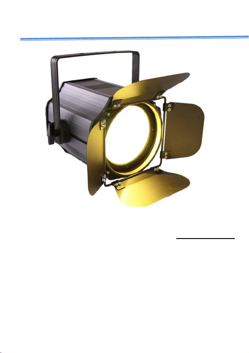
COB200W 2in1 WW+CW led Par Light
User manual
Pleasereadtheinstruction
s ca
refully before use
Page 2

2
TABLE OF CONTENTS
1.Saf
statement
Please keep this User Guide for future consultation. If you sell the unit to another user, be
sure that they also receive this instruction booklet.
etyInstructions
2. Technical Specifications
3. How To Control The Unit
4
. Trouble shooting
5
. Fixture Cleaning
The product has well capability and intact packing when leave factory.
All of the user should comply with warning item and manual, any misuse cause of
the damages are not included in our guarantee, and also can not be
responsible for any malfunction & problem owing to ignore the manual.
........................................................................................................ 2
...............................................................................................4
......................................................................................... 5
.......................................................................................................... 7
...........................................................................................................8
1.Saf
etyInstructions
Unpack and check carefully there is no transportation damage before using the unit.
Before operating, ensure that the voltage and frequency of power supply
match the power requirements of the unit.
It’s important to ground the yellow/green conductor to earth in order to
avoid electric shock.
The unit is for indoor use only. Use only in a dry location.
The unit must be installed in a location with adequate ventilation, at least
50cm from adjacent surfaces. Be sure that no ventilation slots are blocked.
Disconnect main power before replacement or servicing.
Make sure there are no flammable materials close to the unit while operating as it is
fire hazard.
Page 3

3
Use safety cable when fixes this unit. DO NOT handle the unit by taking its head only,
Warning:
Installation:
but always by taking its base.
Maximum ambient temperature is Ta: 40℃. DO NOT operate it where the temperature
is higher than this Unit surface temperature may reach up to 85℃. DO NOT touch the
housing bare-hand during its operation. Turn off the power and allow about 15 minutes
for the unit to cool down before replacing or serving.
In the event of serious operating problem, stop using the unit immediately.Never try
to repair the unit by yourself. Repairs carried out by unskilled people can lead to
damage or malfunction. Please contact the nearest authorized technical assistance
center. Always use the same type spare parts.
DO NOT touch any wire during operation as high voltage might be causing electric
shock.
To prevent or reduce the risk of electrical shock or fire, do not expose the unit to rain
or moisture.
DO NOT open the unit within five minutes after switching off.
The housing, the lenses, or the ultraviolet filter must be replaced if
they are visibly damaged.
Caution:
There are no user serviceable parts inside the unit. DO NOT open the housing or
attempt any repairs yourself. In the unlikely event your unit may require service,
please contact your nearest dealer.
The unit should be mounted via its screw holes on the bracket. Always ensure that the unit
is firmly fixed to avoid vibration and slipping while operating. And make
sure that the structure to which you are attaching the unit is secure and is able to
support a weight of 10 times of the unit’s weight. Also always use a safety cable that
can hold 12 times of the weight of the unit when installing the fixture.
Page 4

4
The equipment must be fixed by professionals. And it must be fixed at a place where is out
2. Technical Specifications
of the touch of people.
Light sources:200w 2in1 WW+CW
Power consumption:200w
Voltage:110-250v/50-60Hz
Dimmer: 0-100%
Beam angle:60degree
Data connectors: 3-pin in & out
Power connectors: powercon in & out
Housing : Die-casting aluminum
Features
Variable electronic strobe.
Variable electronic dimmer (0-100%).and 4 type in optional
LED operation menu with function buttons
Reset to factory settings option. Color temperature setting
Build-in program with speed adjustment
16 bit dimmer effect and White balance
Temperature sensor via software to control fans speed against overheat
Different DMX channel mode. Including STAG, ARC1,AR1D,ARC2,AR2D,AR2S
and HSV
Control
DMX Channel:2/6Channels
Control Modes: DMX512, Master/Slaver/Sound activated,,Auto Run
Construction
Display: Digital Display
Data In/Out socket: 3-pin XLR sockets
Protection Rating: IP20
Page 5
5
3. How To Control The Unit
MENU To select the programming functions
DOWN To go backward in the selected functions
uP To go forward in the selected functions
ENTER To confirm the selected functions
3 Press "ENTER"keys to save and Exit,Press the"MENU"Keys does not save and
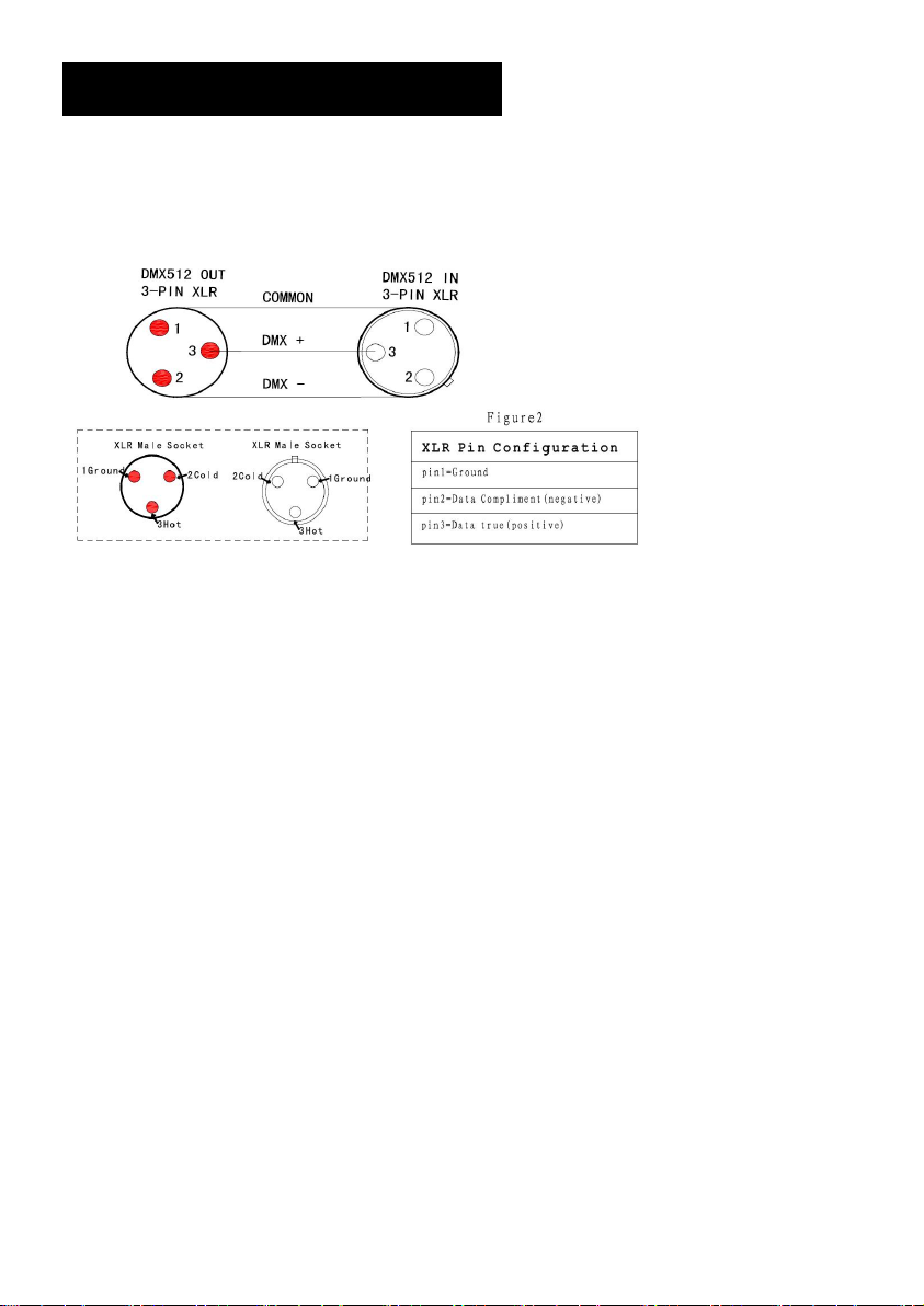
TheDMX512 iswid
controller.connect several lights together,dmx in and dmx out,
3pin
XLRconn
ely
usedinintellig
ectors:Pin1:GND,
ent
lightingcontrol,with a DMX 512
Pin2:Nega
tivesignal(-),
Pin3:Pos
Display:
Se t DMX
Ad d r e s s Co d e
itivesignal(+)
1 Press "Menu" to "Set DMX Address",and press"ENTER" keys to enter into
2 Show "Set DMX Address DMX Address:A001",Press the "UP and DOWN"
keys to amended
Exit
Menu
The device has two operation modes, It can be operated in Stand Alone or in DMX
Page 6
6
controlled
No
Show
Function
Value
Instruction
1
d001
DMX address
001~512
1CH mode,UP,DOWN increase or
reduce the value,
2
A001
DMX address
001~512
2CH mode UP,DOWN increase or
reduce the value
3
S-SL
Dim speed
SL/FA
DMX Dimming speed setting
SL:Slow dimming;
FA:Fast dimming.
4
d-Ho
Signal
lost setting
Ho/oF
DMX Signal loss processing mode:
Ho:Hold the final DMX signal state;
oF: Close all LED
5
u255
WW Dimmer
000~255
Warm White Dimmer- Dark to Bright
6
C255
CW Dimmer
000~255
Cold White Dimmer- Dark to Bright
7
F255
Strobe
007 ~
UP,DOWN change the speed
8
CC15
Colors Jump
00 ~ 15
UP,DOWN change the speed
9
DE15
Colors
Gradate
00 ~ 15
UP,DOWN change the speed
10
CP15
Colors Pulse
00 ~ 15
UP,DOWN change the speed
11
SoUd
sound-Active
/
Sound-Active
12
t 30
Temperature
00-99
Current temperature display.
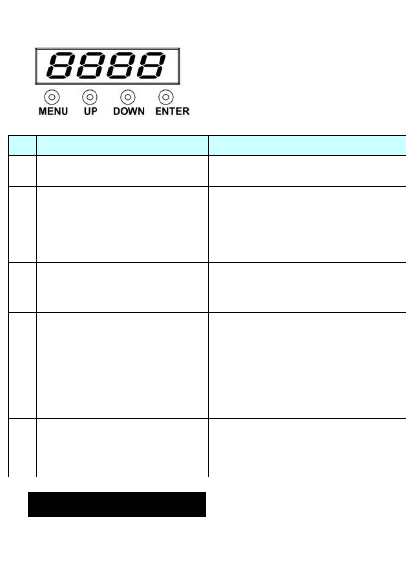
DIGITAL SHOW FUNCTION FORM
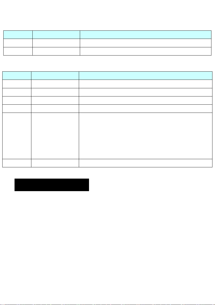
DMX Chart - 2/6 channels
Page 7
7
2 Channels
Channel
Function
Instruction
CH1
WW Dimmer
Warm White Dimmer- Dark to Bright
CH2
CW Dimmer
Cold White Dimmer- Dark to Bright
Channel
Function
Instruction
CH1
Total Dimmer
Dark to Bright
CH2
WW Dimmer
Warm White Dimmer- Dark to Bright
CH3
CW Dimmer
Cold White Dimmer- Dark to Bright
CH4
Total Strobe
005-255 Strobe- 005-255 Slow to Fast
CH5
Function Choice
000~050: CH1-CH6 Control.
051~100: Different Colors output
101~150: Colors Jump Change.
151~200: Colors Gradate.
201~250: Colors Pulse Change.
251~255: Sound-Active
CH6
Function/Speed
Slow to Fast (At the Colors output choose the color)
6 Channels
4. Trouble shooting
F
ollowingarea
suggestionsforeasytroub
A. Theunit
1.Checkthecon
2.Meas
3.Checkthe
B.NotrespondingtoDMXcontroller
urethema
fewcommonpr
doesnot
nect
poweron
work
ion of p
ins
voltageonthemainconnector.
LED
oblemsthatmay occurd
leshooting
:
, nolightandthefandoesnotwor
owerandmainfuse.
.
uring
opera
tion
. Herearesom
k
e
Page 8

8
1.DMXLED shouldbeon.Ifnot,checkDMXcon
nectors,cablestoseeif
link
properly
2.
DMXpolar
3.Ifyouhaveintermittent DMXsignalproblems,checkthep
PCBoftheu
4.TrytouseanotherDMXcontroller
5.CheckiftheDMXcablesrunnearor runalongsidetohighvoltagecab
C
1.Thestepper
2.Themotor’sdriveIConthe
.
If theDMXLEDisona
ity
.
nitorthepreviouson
damageorin
. Oneofthe
terfer
ence
channelsisnotwork
motormightbedamagedor
nd noresponsetothechannel,
e.
.
to DMX
inter
face
circui
t.
ingwel
thecablecon
PCBmightbeoutofco
l
checktheaddr
insonc
nectedto thePCBisbroken.
ndition.
onn
5. Fixture Cleaning
ess s
ettingsand
ectorsoron
lesthatmaycause
Theclean
p
eriodica
inwhichthef
greateraccumula
ev
ingof
internalandexternal
lly to optimize
ixture
tionofdirtontheu
Cleanwithsoft
Alwaysdrythepartscarefully
Cleantheexternal
ery
30/60
days.
lightou
opera
tes:damp,smoky orpar
clothusingnormalglass
optic
s atleastev
opticallensesa
tput.Cleaningfreq
nit’soptics.
.
ery20days. Cleantheinternal
nd/or mirr
uencydependsontheenvironm
tic
ularly dirtysurr
cleaning
fluid
orsmustbecarriedout
ound
ingcancaus
.
opticsatleast
ent
e
 Loading...